AUTOMATIC GENERATION OF LINE-BASED CUBISM-LIKE ART IMAGES AND THEIR APPLICATION TO DATA HIDING
1Shan-Chun Liu (劉珊君)and 2Wen-Hsiang Tsai (蔡文祥)
1
Institute of Computer Science and Engineering National Chiao Tung University, Hsinchu, Taiwan
E-mail: [email protected]
2
Dept. of Computer Science
National Chiao Tung University, Hsinchu, Taiwan E-mail: [email protected]
ABSTRACT
A new type of computer art, called line-based Cubism- like image, is proposed, which keeps a characteristic of the Cubism art ⎯ multiple viewpoints ⎯ by the use of line and region features. In the creation process with an input source image, prominent line segments in the image are detected and rearranged to form an abstract region-type art image of the Cubism flavor. In a process of re-coloring the regions in the generated art image, a data hiding technique for covert communication is designed skillfully to embed secret message bits in the pixels’ colors by keeping the average region color unchanged. Experimental results show the feasibility of the proposed method.
Keywords: art image; line-based Cubism-like image;
data hiding; cover image; stego-image; secret message.
1. INTRODUCTION
In recent years, the topic of creating art images via the use of computers arouses interests of many people.
Many methods have been proposed to create art images automatically [1]-[9].
Hertzmann [1] surveys many ideas of creating art images by stroke-based rendering (SBR), which is defined to be an automatic approach to creating non- photorealistic imagery by placing discrete elements, like paint strokes and stipples, in the resulting image. He also surveyed several SBR algorithms and styles such as painting, pen-and-ink drawing, tile mosaics, and so on.
The common goal of creating these image styles is to make generated art images look like some other types of images. For example, two images created by watercolor painting and oil painting in Hertzmann [2] and Hertzmann [3], respectively, are shown in Fig. 1. Some other types of art images are shown in Fig. 2, where Fig.
2(a) is an image created by pen-and-ink illustration
proposed by Salisbury [4], Fig. 2(b) is a stipple image created by a stipple placement method proposed by Mould [5], and Fig. 2(c) shows a stain-glass image created by an image filtering scheme presented in Mould [6].
(a) (b)
(c) (d) Fig. 1: The images created by Hertzmann [2] and
Hertzmann [3]. (a) and (b) Effect of watercolor painting [2]. (c) and (d) Effect of oil painting [3].
(a) (b) (c) Fig. 2: Some types of art images. (a) A pen-and-ink drawing from Salisbury [4]. (b) A stipple image from Mould [5]. (c) A stained glass image from Mould [6].
Another type of art image is mosaic image. Each mosaic image is composed of small shapes, such as squares, circles, triangles, and so on. Different from using fixed orientations for tile arrangements in traditional mosaic generation schemes, Hausner [7]
creates a new type of tile mosaic image by placing tiles
to follow the edges in the input image to make the created art image smoother. Fig. 3 shows some examples from Hausner [7]. Another important criterion for art image creation is to limit the number of strokes so that the resulting image looks like an abstract painting, such as the images shown in Fig. 4 which come from Haeberli [8]. Besides, Song, et al. [9]
produces an abstract synthetic art by fitting shapes like triangles or rectangles to the regions in segmented images, like the ones shown in Fig. 5.
Fig. 3: Tile mosaic images created by Hausner [7].
Fig. 4: Images created by Haeberli’s method [8].
Fig. 5: Images created by Song, et al. [9].
In this study, we try to use the line feature used in Cubism paintings to create an abstract type of line- dominated art image, called line-based Cubism-like image. Two examples of such images created in this study are shown in Fig. 6.
On the other hand, data hiding is a technique which embeds data imperceptibly into cover images, so that people will not perceive the existence of the hidden data.
Data hiding techniques often utilize the weaknesses of the human visual system in differentiating small color or grayscale differences. A well-known method is least significant bit (LSB) modification which changes the LSBs of the pixels of an image to embed information, like Chan and Cheng [10]. Another is the contrast- keeping data embedding scheme proposed by Wu and Tsai [11]. Also, to achieve recoverability of the cover image from the stego-image, which requires lossless data embedding, the most common approach is to compress a portion of the cover image and embed the result with the intended payload into the cover image,
such as Fridrich, et al. [12] and Awrangjeb and Kankanhalli [13]. Another approach is to manipulate a group of pixels as a unit to embed a bit of information, like Tian [14] and Vleeschouwer, et al. [15]. A third approach is to use the technique of histogram shifting which can embed large volumes of data, e.g., Ni, et al.
[16] and Lee and Tsai [17]. In this study, we use a new scheme of keeping average region colors unchanged to achieve the goal of lossless data hiding. Note that there exist very few lossless data hiding techniques so far.
(a) (b)
(c) (d) Fig. 6: Two examples of line-based Cubism-like images created
in this study.
Moreover, the combination of data hiding and art image creation techniques is a new idea for information hiding applicatios. Techniques based on this idea utilize the characteristics of the creation process of the art image to embed extra information in the generated image. Attracted by the art exhibited by the image, people will pay no attention to the hidden secret data in the art image. Due to this way of camouflage, secret data can be kept or transmitted covertly and securely. In this study, we hide secret message in the proposed Cubism-like image during the image creation process by changing the colors of the pixels in image regions slightly while keeping the average colors of the regions unchanged. The color differences in the resulting image are difficult to be found by attackers because of the weaknesses of the human visual system in discriminating small color changes.
In the remainder of this paper, we describe the proposed technique for creating the line-based Cubism- like art image in Section 2, the proposed data hiding technique in Section 3, followed by conclusions in Section 4. Experimental results are also shown in Sections 2 and 3 to demonstrate the feasibility of the proposed method.
2. PROPOSED LINE-BASED CUBISM-LIKE IMAGE CREATION PROCESS
2.1. Idea of Line-based Cubism-like Image Creation Cubism artists transform a natural scene into geometric forms by breaking up, analyzing, and re-assembling objects in the scene. In addition, with the scene objects rearranged to intersect at random angles, each painting
of Cubism appears to be composed of intersecting lines and fragmented shapes in an abstract style. The idea of the proposed art image creation method is inspired by these concepts of Cubism, as mentioned previously.
In the creation process of a line-based Cubism-like image from a given source image, at first we find the prominent line segments in the image by edge detection and the Hough transform. Then, we connect the line segments and extend them to reach the image boundaries. Finally, we generate the desired art image via the operations of line segment merging and region re-coloring. This process accomplishes the goal of transforming the input image into an abstract form since the lines of the created Cubism-like image tend to constitute the skeleton of the objects in the source image as observed from our experimental results.
2.2. Creation of Line-based Cubism-like Image The proposed art image creation process is composed of two major procedures. Basically, in the process of line detection, we find edges in the source image by Canny edge detection [18] and the Hough transform [19]. Then, we filter out short line segments, as well as line segments which are too close to other longer lines. Then we extend and recombine the remaining prominent line segments to form the skeleton of the objects in the source image. Finally, a desired Cubism-like image is created by coloring the resulting regions. The detail is described in the following algorithm.
Algorithm 1: line-based Cubism-like image creation.
Input: a source image S, and two threshold values ⎯ the minimum line segment length Lmin and the minimum between-line distance Dmin.
Output: a line-based Cubism-like image C.
Steps.
Stage 1 --- creating crossing-image lines.
Step 1. Perform Canny edge detection to find the edge points in source image S, resulting in a new image S′.
Step 2. Perform the following steps to find prominent line segments in S′.
2.1 Find line segments L1, L2, …, Lm, in S′ by applying the Hough transform on S′, yielding a second new image S′′ of the line type.
2.2 Select those line segments in S′′ with lengths larger than threshold Lmin.
2.3 Compare every line pair Li and Lj with i ≠ j in S′′ and if the distance Dij between Li and Lj is smaller than Dmin, then delete Li if the length of Li is smaller than that of Lj; or delete Lj, otherwise.
Step 3. Extend each of the remaining line segments in S′′ to the boundaries of S′′, and regard the source image S as being partitioned by these extended lines to form regions.
Stage 2 --- re-coloring image regions.
Step 4. Create a binary image T of the size of S with initial pixel values all set to be 0.
Step 5. Fill the value of 1 into those pixels in T which correspond to those lying on each of the extended line segments in S′′.
Step 6. Perform following steps to re-color the regions in S.
6.1 Perform region growing in the binary image T in a raster-scan order, and segment out 0- valued regions, R1, R2, …, Rk, each of which is enclosed by a group of 1-valued line segments in S′′.
6.2 Compute the area Ai of each segmented region Ri in T and the average RGB color values (Cir, Cig, Cib) of the corresponding region Ri′ in S using Ai, and re-color each pixel in Ri′ of S by the color values (Cir, Cig, Cib), i = 1, 2, …, k.
6.3 Re-color all lines in S corresponding to the 1-valued extended lines in T by the white color.
Step 7. Take the final S as the desired line-based Cubism-like image C.
2.3. Experimental Results
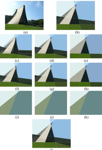
According to the above discussions, we see that different selections of the two threshold values Lmin and Dmin will result in totally different effects in the created art images. However, it is difficult to decide which result is better than the others because the decision is obviously dependent on people’s different feelings of art. Therefore, in this study we just offer a series of results yielded by the use of different sets of thresholds for the user to inspect and choose. Specifically, we use the three values of 0.5/10, 1/10, and 2/10 times the length of the longer image boundary as the values for each of the thresholds Lmin and Dmin. As a result, each threshold has three choices, resulting in nine choices of the two threshold values. Then, we generate nine art images, each corresponding to one of the nine threshold combinations, for the user to choose his/her favorite one.
An example is shown in Fig. 7.
3. PROPOSED DATA HIDING TECHNIQUE 3.1. Idea of Proposed Technique
In the proposed Cubism-like image creation process as presented by Algorithm 1 above, the main idea is to re- color the pixels in each image region with the average color of all the pixels in the region with the resulting image visually looking like the original one.
About the proposed data hiding technique, it is pointed out first that due to the nature of the human visual system, people cannot sense small changes in the appearance of a color image, such as color alternations or edge shiftings. Therefore, the proposed data hiding technique is designed to hide a secret message into a cover image ⎯ a line-based cubism-like image generated by the proposed creation method described
previously ⎯ by changing slightly the rgb color values of the pixels in each region of the cover image. As a result, people will not be able to distinguish the difference between the cover image and the stego-one.
It is in this way that we achieve the goal of data hiding in the proposed line-based Cubism-like art image without arousing suspicions from hackers.
(a) (b)
(c) (d) (e)
(f) (g) (h)
(i) (j) (k)
(l)
Fig. 7: Experimental results. (a) A source image with size 1024×768. (b) Initial Dmin = 102 and initial Lmin = 102. (c) (Dmin, Lmin) = (51, 51). (d) (Dmin, Lmin) = (51, 102). (e) (Dmin, Lmin) = (51, 204). (f) (Dmin, Lmin) = (102, 51). (g) (Dmin, Lmin) = (102, 102). (h) (Dmin, Lmin) = (102, 204). (i) (Dmin, Lmin) = (204, 51). (j) (Dmin, Lmin)
= (204, 102). (k) (Dmin, Lmin) = (204, 204). (l) A better choice of 9 images to fit the abstract style of Fig. 1(a) is Dmin=102 and Lmin=51.
Furthermore, for the reason of achieving reversibility in the hidden data extraction process, a reversible region re-coloring technique, which keeps the average color of each region unchanged, is proposed.
Consequently, we can restore the color information of the pixels in the stego-image perfectly after extracting the secret messages embedded in them. More specifically, in the proposed data hiding process, after the step of hiding message bits into a color channel, the pixel colors in a region will be changed via color shifting, and the average color of the region will also be influenced. In order to keep the average color unchanged as desired, we limit the number of message bits embedded into the region. For this purpose, it is found in the study that the property of rounding-off of
integer computation may be utilized. Specifically, when computing the average color C of a region, all the computed results in the range between C − 0.5 and C + 0.5 will be rounded to be an identical value since color values used in this study are integer numbers.
Accordingly, we can acquire the maximum number of embedded bits in a region as derived in the following.
Assume that A is the total number of pixels in a region R (in unit of pixel), Cr1, Cr2, …, Crn are the r- color values of the n pixels in region R, and Cr is the average r-color value of region R. Also, let N0 and N1
denote the total numbers of bits of 0’s and 1’s embedded in R. At first, the average r-color value Cr of all the pixels in R may be computed by
Cr = (Cr1 + Cr2 + … + Crn)/A.
Therefore, we have
CrA = Cr1 + Cr2 + …+ Crn.
Furthermore, we hide the secret message bits by shifting the average r-color value of each pixel in this study. We assume that when hiding a bit of 0 into a pixel P in region R with average r-color value Cr, the pixel’s color Cr is decreased by 1; and when hiding a bit of 1 into P, the pixel’s color Cr is increased by 1. Therefore, if N0
0’s and N1 1’s are embedded into the pixels of region R, then it can be figured out that the average r-color value Cr of R will increase for the amount of N1 – N0 (or equivalently, decrease for the amount of N0 – N1), so that the new average color Cr′ becomes:
Cr′ = (Cr1 + Cr2 + …+ Crn + N1 – N0)/A
= (CrA + N1 – N0)/A.
To keep the new average color Cr′ equal to the original one Cr, we have to limit the values of the two numbers N1 and N0 according to the above-mentioned rounding- off property, resulting in the following formula:
Cr – (1/2) ≤ Cr′ = (CrA + N1 – N0)/A < Cr + (1/2) which can be reduced to be
–A/2 ≤ N1 – N0 < A/2. (1) As a summary, the values of N1 and N0 together are
limited by the total number A of pixels in the region, implying that the data hiding capacity is also restricted by it. In the best case, we know that the maximum number of embeddable bits in a region is just the number A of pixels in the region, that is,
N1 + N0 = A. (2)
Now, according to Equations (1) and (2), we can derive the ranges of N1 and N0 to be as follows (the details omitted):
A/4 ≤ N0 < 3A/4, (3)
A/4 ≤ N1 < 3A/4. (4)
In the extreme case where the digit sequence is composed of all 0’s or all 1’s, the upper bound of the data hiding capacity will be reached, which is ⎣A/2⎦ − 1, as can be figured out from Equation (1).
In this study, we keep the average region color unchanged for two reasons. The first, as mentioned previously, is to make possible recovery of the region information in the data extraction process, where we use the average color as a basis to extract the hidden secret message. The other reason is to yield a visually mosaic effect so that the region color that people see is almost the same, despite of the color shifting inside the region.
3.2. Proposed Data Hiding Process
The proposed data hiding process, which is based on the creation process of the line-based Cubism-like image, is described in detail in this section. As described in the last step of Algorithm 1, we re-color each region of the input image by the average color of the region to generate the desired Cubism-like image. For the purpose of hiding data in the generated Cubism-like image, we try to modify this re-coloring process to achieve secret message hiding.
Specifically, the data hiding process is composed of two main stages. First, we transform the secret massage into a digit sequence and append an ending pattern (with at least one digit) at the end of the digit sequence to keep the sequence length a multiple of three. By the ending pattern, we can determine where the massage ends in a sequence of extracted bits in the message extraction process. Next, we try to obtain the information of two parameters of each region, namely, the region area and the average rgb color values in the region, by performing Algorithm 1. Furthermore, we use a secret key to randomize the order of re-coloring of the regions in the input image, and take the resulting new sequence as the order for data hiding. For each region, we compute the maximum data hiding capacity.
In order to keep the average rgb color of the region unchanged, we limit the embedded amount of message bits in each region as described previously. After getting the maximum data hiding capacity, we embed the message bits by shifting the color values of the pixels in each region according to the above-mentioned data hiding order. After the digit sequence is exhausted, there might exist regions in which no message bit is embedded. We deal further with these intact regions to keep the coloring style of all regions consistent. By creating a new binary string whose size is the upper bound of the data hiding capacity and constituting randomly a string with 0’s and 1’s by the secret key, we use the same process to re-color the pixels in these regions according to the resulting binary string. At the end, a stego-image is generated with the secret message embedded. The detailed algorithm to implement these steps is given as follows.
Algorithm 2: embedding a secret message into a line- based Cubism-like image.
Input: a cover image S, a secret key K, a secret message M in character form, and two threshold values
⎯ the minimum line segment length Lmin and the minimum between-line distance Dmin.
Output: a stego-image I into which M is embedded.
Steps.
Stage 1 --- embedding a secret message M.
Step 1. Transform the secret massage M in character form into a bit sequence M′, and randomize the bits in M′ by the secret key K.
Step 2. Transform each bit of M′ into a digit, resulting in a digit sequence M′′, and append an ending pattern with at least one and no more than three identical digits de other than 0’s and 1 at the end of M′′ to form a new digit sequence with its length being a multiple of three.
Step 3. Divide M′′ into a sequence of 3-digit segments m1, m2, …, mn.
Step 4. Perform Algorithm 1, using the input cover image S as the source image, to obtain the information of two parameters of the regions R1, R2, …, Rk in S, namely, the areas A1, A2, …, Ak
and the average rgb color values (C1r, C1g, C1b), (C2r, C2g, C2b), …, (Ckr, Ckg, Ckb) of the regions R1, R2, …, Rk, respectively.
Step 5. Rearrange randomly the coloring order of the regions by the secret key K, resulting in a new coloring sequence Cs = {R1′, R2′, …, Rk′}; and change accordingly the corresponding orders of the areas and the average rgb color values, resulting in the new orders of A1′, A2′, …, Ak′ and (C1r′, C1g′, C1b′), (C2r′, C2g′, C2b′), …, (Ckr′, Ckg′, Ckb′), respectively.
Step 6. Calculate the maximum data hiding capacity Qi
of each region Ri′ in accordance with the new coloring sequence Cs by the following steps with the initial value of Qi being set to be zero.
6.1 Assign each 3-digit segment mt = drdgdb of the digit sequence M′′ into one of six groups Nr0, Nr1, Ng0, Ng1, Nb0, and Nb1 in the following way:
(a) increase Nr0 by 1 if dr = 0; and increase Nr1 by 1 if dr = 1;
(b) increase Ng0 by 1 if dg = 0; and increase Ng1 by 1 if dg = 1;
(c) increase Nb0 by 1 if db = 0; and increase Nb1 by 1 if db = 1.
6.2 Compute the maximum data hiding capacity Qi of each region Ri′ by the following operations.
(a) If Nr1 – Nr0 ≥ Ai′/2 or Nr1 – Nr0 <
–
Ai′/2, take the current Qi to be the maximum data hiding capacity.(b) If Ng1 – Ng0 ≥ Ai′/2 or Ng1 – Ng0 <
–
Ai′/2, take the current Qi to be the maximum data hiding capacity.(c) If Nb1 – Nb0 ≥ Ai′/2 or Nb1 – Nb0 <
–
Ai′/2, take the current Qi to be the maximum data hiding capacity.(d) Increase the data hiding capacity Qi by 3 if Qi has not been set to be the maximum data hiding capacity.
6.3 Repeat Steps 6.1 and 6.2 until Qi has been taken to be the maximum data hiding capacity or until the digit sequence M′′ is exhausted.
Step 7. Perform the following steps to embed the secret message digits into each region Ri′.
7.1 Reorder randomly the pixels in Ri′, which is initially in a raster-scan order, into a hiding sequence Hs = {p1, p2 , …, pt}, by using the secret key K and the index i of Ri′ in the coloring sequence Cs as the seed for the randomization process.
7.2 Embed each 3-digit segment mt = drdgdb of the digit sequence M′′ into a pixel pj of Ri′ according to the hiding sequence Hs in the following way.
(a) Obtain new average rgb color values (Cjr′′, Cjg′′, Cjb′′) of each pixel pj in S by shifting in order the original average rgb color values (Cjr′, Cjg′, Cjb′) of pj in the following way, where h = r, g, and b:
i. decrease Cjh′by 1 if dh = 0;
ii. increase Cjh′ by 1 if dh = 1;
iii. do nothing Cjh′ if dh = de (the ending pattern digit).
(b) Re-color the pixel pj by the new rgb color values (Cjr′′, Cjg′′, Cjb′′).
(c) Decrease the data hiding capacity Qi by 3.
(d) Repeat the above two steps until the maximum data hiding capacity Qi is exhausted.
Step 8. Repeat Steps 6 and 7 if the digit sequence of M′′
is not exhausted.
Stage 2 --- dealing with intact regions.
Step 9. Perform the following steps to deal with each intact region Rl′ with area Al′ which has not been used for message bit embedding so far.
9.1 Use the secret key K to create a binary string B with size ⎣Al′/2⎦ − 1 for Rl′ , which is composed of a random sequence of 0’s and 1’s.
9.2 Perform Steps 6 through 8 to re-color the pixels of Rl′ to embed the binary string B.
Step 10. Take the final S as the desired stego-image I.
In the above algorithm, wrap-around problems might occur in Steps of 7.2(a)-i and 7.2(a)-ii when the average color value in a color channel is 255 or 0. In this case, we will obtain a bad stego-image with some noise (black or white image points) after 1 is added to 255 or 1 is subtracted from 0. To avoid such extreme cases, we adjust the extreme average color values of 255 and 0 to be 254 and 1, respectively, before data hiding. Such slight color alternations in the generated stego-image cause nearly no visual effect to the human vision but can solve the wrap-around problem.
3.3. Secret Extraction Process
In the proposed secret message extraction process, first we recover the coloring sequence in the stego-image.
By a region growing scheme, we get the information of the regions with an initial order sequence. Then, we retrieve the coloring sequence by using the secret key.
Moreover, in the process of region growing, we also obtain the area and the average color of each region in the stego-image. Based on the average region color values, we can retrieve accordingly the secret message embedded in a region in the stego-image by comparing the average region color and those of the pixels in the region. The algorithm of secret data extraction is described in detail as follows.
Algorithm 3: extracting a secret message from a stego-image.
Input: a stego-image S, and a secret key K identical to that used in Algorithm 2.
Output: the secret message M embedded in S.
Steps.
Stage 1 --- retrieving information of the stego-image.
Step 1. Perform region growing in a raster-scan order to segment out regions, R1, R2, …, Rk, in S, and obtain the information about the area A1, A2, …, Ak and the average rgb color values (C1r, C1g, C1b), (C2r, C2g, C2b), …, (Ckr, Ckg, Ckb) of the regions, respectively.
Step 2. Retrieve the coloring order of regions by the secret key K, denote the result as Cs = {R1′, R2′, …, Rk′}, and change the corresponding orders of the areas and the average rgb color values of the regions, resulting in the new order sequences of areas A1′, A2′, …, Ak′ and average color values (C1r′, C1g′, C1b′), (C2r′, C2g′, C2b′), …, (Ckr′, Ckg′, Ckb′), respectively.
Stage 2 --- extracting the embedded data.
Step 3. Create an empty digit sequence Q initially.
Step 4. Perform the following steps to extract the secret message M from S.
4.1 Randomize the pixel order in Ri′, which initially is in a raster-scan order, and denote the result as a recovered sequence Hs = {p1, p2 , …, pT}, using the secret key K and the index of Ri′ in the coloring sequence Cs
together as the seed of the randomization process.
4.2 Obtain the rgb color values of each pixel pj
of Ri′ according to sequence Hs and denote them by (Cjr′′, Cjg′′, Cjb′′).
4.3 Acquire three digits Qjr, Qjg, and Qjb from the differences between the rgb color values (Cjr′′, Cjg′′, Cjb′′) of each pixel pj and the average rgb color values (Cir′, Cig′, Cib′) of region Ri′, respectively, by the following way:
(a) if any of the color values (Cjr′′, Cjg′′, Cjb′′) is smaller than the corresponding average color value in (Cir′, Cig′, Cib′),
then set the corresponding value Qjr, Qjg, or Qjb to be 0;
(b) if any of the color values (Cjr′′, Cjg′′, Cjb′′) is larger than the average color (Cir′, Cig′, Cib′), then set the corresponding value Qjr, Qjg, or Qjb to be 1;
(c) if any of the color values in (Cjr′′, Cjg′′, Cjb′′) is equal to the corresponding average color value in (Cir′, Cig′, Cib′), then set the corresponding value in (Qir, Qig, Qib) to be de (the ending pattern digit).
4.4 Store the three digits Qir, Qig, and Qib into Q in order.
4.5 Repeat Steps 4.1 through 4.4 until a value in Q equal to de (the ending pattern digit) is encountered.
Step 5. Use the secret key K to reorder Q.
Step 6. Transform Q into character form as the desired secret message M.
3.4. Experimental Results
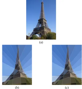
Figs. 8 through 13 show some experimental results of applying the proposed data hiding method to two images. Figs. 8(a) and 11(a) are the source images. Figs.
8(b) and 11(b) are the generated Cubism-like images with no secret message embedded. Fig. 8(c) is a stego- image into which a secret message “Meet me at 21:30.
See you.” has been embedded with the secret key “test.”
Fig. 11(c) is a stego-image into which a secret message
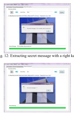
“Hi, I am Helen. Nice to meet you!” has been embedded with the secret key “door.”The secret message can be retrieved only when the right key is used in the secret message extraction process, like the results of Figs. 9 and 12. If a wrong key is used in the secret extraction process, the extraction work will fail, as shown by the examples in Figs. 10 and 13.
4. CONCLUSIONS
In this paper, a new method of combining art image generation and data hiding to enhance the camouflage effect for various information hiding applications is proposed. At first, a new type of computer art, called line-based Cubism-like image, and a technique to create it automatically from a source image have been proposed. The method finds line segments in the source image by the Canny edge detection technique and the Hough transform, combines nearby line segments, extends the remaining lines to the image boundaries, and re-color the created regions by their average colors, to create an abstract type of the original source image as the desired art image. Then, by utilizing the characteristics of the Cubism-like image creation process, a data hiding technique has been proposed.
Based on the minimum color shiftings of the values of
±1, the technique embeds message data into the pixels
of the regions of the generated art image while keeping the average region colors unchanged. The data embedding process is proved to be lossless by theorems so that the cover image can be recovered perfectly after the embedded message data are extracted.
The proposed method has several merits. First, it generates Cubism-like images as stego-images to distract the hacker ' s attention to the message data embedded in them. Also, by using the minimum color shiftings of ±1 to embed data bits, the resulting pixels’
color differences between the generated Cubism-like image and the stego-image are so small that a hacker will take no notice of the existence of the hidden data.
Consequently, the proposed data hiding technique is very suitable for use in covert communication or secret keeping. Furthermore, four measures of randomization of the input message data and the processing order of them with a secret key and several random-number generating functions have been adopted in the proposed method. This enhances greatly the security of the proposed method.
(a)
(b) (c) Fig. 8: An experimental result. (a) Source image. (b) A
Cubism-like image without secret message embedding. (c) A stego-image of (a) into which secret messages are hidden.
Fig. 9: Extracting secret message with the right secret key.
[2] A. Hertzmann, “Painterly rendering with curved brush strokes of multiple sizes,” Proc. SIGGRAPH 1998, Orlando, Florida, USA, pp. 453-460, July 1998.
Fig. 10: Extracting incorrect message with a wrong key.
[3] A. Hertzmann, “Fast paint texture,” Proc. SIGGRAPH 2002, Annecy, France, June 3-5, pp. 91-96, 2002.
[4] M. P. Salisbury, M. T. Wong, J. F. Hughes, and D. H.
Salesin, “Orientable textures for image-based pen-and- ink illustration,” Proc. SIGGRAPH 1997, Los Angeles, California, USA, pp. 401-406, 1997.
(a)
(b) (c) Fig. 11: Another experimental result. (a) Source image. (b) A
Cubism-like image without secret message embedding. (c) A stego-image of (a) into which secret messages are hidden.
[5] D. Mould, “Stipple placement using distance in a weighted graph,” Proc. Int’l Symp. on Computational Aesthetics in Graphics, Visualization & Imaging, Banff, Alberta, Canada, pp. 45-52, 2007.
[6] D. Mould, “A stained glass image filter,” Proc. of 14th Eurographics Workshop on Rendering, Leuven, Belgium, pp. 20-25, 2003.
[7] A. Hausner, “Simulating decorative mosaics,” Proc.
SIGGRAPH 2001, Los Angeles, California, USA, pp.
573-580, August 2001.
[8] P. Haeberli, “Paint by numbers: abstract image representations,” Proc. SIGGRAPH 1990, Dallas, Texas, USA, pp. 207-214, 1990.
[9] Y. Z. Song, P. L. Rosin, P. M. Hall, and J. Collomosse,
“Arty shapes,” Proc. Computational Aesthetics in Graphics, Visualization & Imaging, Lisbon, Portugal, pp.
65-72, 2008.
[10] C. K. Chan and L. M. Cheng, “Hiding data in images by simple LSB substitution,” Pattern Recog., vol. 37, pp.
469-474, March 2004.
[11] D. C. Wu and W. H. Tsai, “Embedding of any type of data in images based on a human visual model and multiple-based number conversion,” Pattern Recog.
Letters, vol. 20, pp. 1511-1517, August 1999.
[12] J. Fridrich, M. Goljan and R. Du, “Lossless data Embedding—new paradigm in digital watermarking,”
EURASIP J. on Applied Signal Processing, vol. 2, pp.
185–196, 2002.
Fig. 12: Extracting secret message with a right key.
[13] M. Awrangjeb and M. S. Kankanhalli, “Reversible watermarking using a perceptual model,” J. of Electron.
Imag., vol. 14, no. 013014, Mar. 2005.
[14] J. Tian, “Reversible data embedding using a difference expansion,” IEEE Trans. on Circuits Syst. & Video Technol., vol. 13, no. 8, pp. 890–896, Aug. 2003.
[15] C. de Vleeschouwer, J. F. Delaigle and B. Macq,
“Circular interpretation of bijective transformations in lossless watermarking for media asset management,”
IEEE Trans. on Multimedia, vol. 5, no. 1, pp. 97–105, Mar. 2003.
Fig. 13: Extracting incorrect message with a wrong key.
[16] Z. Ni, Y. Q. Shi, N. Ansari and W. Su, “Reversible Data Hiding,” IEEE Trans. on Circuits Syst. & Video Technol., vol. 16, no. 3, pp. 354-362, March 2006.
[17] C. W. Lee and W. H. Tsai, “A lossless large-volume data hiding method based on histogram shifting using an optimal hierarchical block division scheme,” J. of Inform. Sci. & Eng., vol. 27, no. 4, pp. 1265-1282, 2011.
[18] J. Canny, “A computational approach to edge detection,” IEEE Trans. Pattern Analysis & Machine Intelligence, vol. 8, no. 6, pp. 679-698, 1986.
[19] R. C. Gonzalez and R. E. Woods, Digital image processing. 2nd ed., Prentice Hall, Upper Saddle River, New Jersey, USA, 2002.
REFERENCES
[1] A. Hertzmann, “A survey of stroke-based rendering,”
IEEE Computer Graphics and Applications, vol. 23, no.
4, pp. 70-81, July-Aug. 2003.
![Fig. 4: Images created by Haeberli’s method [8].](https://thumb-ap.123doks.com/thumbv2/9libinfo/9650690.674047/2.892.106.392.303.766/fig-images-created-haeberli-s-method.webp)