國 立 交 通 大 學
多媒體工程研究所
碩 士 論 文
對 MPEG 環場音訊壓縮子頻‐時間處理之改善
An Improved Subband Domain Temporal Processing for MPEG
Surround Audio Coding
研 究 生: 董昀修
指導教授: 蕭旭峯 教授
劉啟民 教授
中 華 民 國 九 十 九 年 十 一 月
對 MPEG 環場音訊壓縮子頻‐時間處理之改善
An Improved Subband Domain Temporal Processing for MPEG
Surround Audio Coding
研 究 生:董昀修
Student: Yun‐Hsiu Tung
指導教授:蕭旭峯
Advisor: Dr. Hsu‐Feng Hsiao
劉啟民 Dr. Chi‐Min Liu
國 立 交 通 大 學
多 媒 體 工 程 研 究 所
碩 士 論 文
A Thesis Submitted to Institute of Multimedia Engineering College of Computer Science National Chiao Tung University in partial Fulfillment of the Requirements for the Degree of Master in Computer Science November 2010 Hsinchu, Taiwan, Republic of China中 華 民 國 九 十 九 年 十 一 月
對 MPEG 環場音訊壓縮子頻‐時間處理之改善
學生:董昀修 指導教授:蕭旭峯 博士
劉啟民 博士 國立交通大學多媒體工程研究所碩士班
中文論文摘要
MPEG Surround Audio Coding 是一個低位元率多聲道音訊壓縮的標準。其壓縮的概 念是利用降混音(down‐mix)的處理和計算空間參數(spatial parameter)的方式來減少聲道 數。而解碼端則是將耦合訊號經過去相關器(decorrelator)的處理,所產生出的去相關訊 號再根據空間參數進行升混音(up‐mix)處理來重建聲源定位與空間寬廣度的環繞效果。 但訊號在經過去相關器的處理後,在暫態(transient)處會被破壞造成感官聽覺上的影響。 MPEG Surround 為此提供了 Subband Domain Temporal Processing (STP) 工具來解決這個 問題,但就客觀測試和主觀測試後的結果發現,經 STP 處理後反而都是比較差的情況。
此篇論文會針對 STP 在做法上進行一些修改,藉此來改善在主觀測試和客觀測試上 的結果。
An Improved Subband Domain Temporal Processing for MPEG
Surround Audio Coding
Student: Yun‐Hsiu Tung Advisor: Dr. Hsu‐Feng Hsiao Dr. Chi‐Min Liu Institute of Multimedia Engineering National Chiao Tung University
Abstract
MPEG Surround Audio Coding is an efficient compression standard of high‐quality multichannel sound. The compression concept uses down‐mix and spatial parameters calculation to reduce the channel number and achieve high compression rate. In decoder, an upmixing module can reconstruct the multichannel signals by using the output signal of decorrelator and the spatial parameters. After the signal is processed by decorrelator, the transient property has been destroyed, affecting the perceptual listening quality. In order to overcome the defect, MPS proposes Subband Domain Temporal Processing (STP) shaping tool. However, the objective and subjective quality assessments still show negative results on the STP‐processed signals. This thesis modifies the current STP structure for improving the results of the quality assessments.
Acknowledgement
In these years at NCTU, I would like to thank my advisors, Prof. Hsu‐Feng Hsiao and Prof. Chi‐Min Liu, who gave me a lot of valuable suggestions making me able to break through on my research, and they were very patient with me to teach any skills on research. Others, such as lab members and friends, encouraged me to overcome any problem, especially Dr. Han‐Wen Hsu, Mr. Der‐Pei Chen and Mr. Chun‐Yu Pan, they gave me assistances when I was helpless and cheered me up when I was discouraged. Because of them, I got the strength to face the difficulties during my research. Without them I could not have completed my research. I want to express my most sincere gratitude to my lovely family and girlfriend for their firm support that let me finish my master degree. Therefore, I would like to share this honor with them. 2010/10/31
Table of Contents
中文論文摘要 ... III Abstract ... IV Acknowledgement ... V Chapter 1. Introduction ... 1 Chapter 2. Backgrounds ... 3 2.1. Spatial Audio Coding ... 3 2.2. MPEG Surround ... 4 2.3. Decorreletors ... 7 2.4. Subband Domain Temporal Processing ... 9 Chapter 3. Problem Definition ... 14 Chapter 4. Proposed Method ... 18 Chapter 5. Experiments and Results ... 23 5.1. MPEG Surround Reference Software RM0 ... 23 5.2. Quality Measurement ... 23 5.3. Test Tracks ... 24 5.4. Spectrum Comparison ... 25 5.5. Scale Factors Comparison ... 28 5.6. Results of Objective Quality Measure ... 29 5.7. Results of Subjective Quality Measure ... 31 5.8. Time‐of‐Usage ... 31 Chapter 6. Conclusion and Future Work ... 36Figure List
Figure 1 The concept of the MPEG Surround system [1] ... 1 Figure 2 Basic concept of the spatial audio coding [4] ... 4 Figure 3 MPS Encoder for 5151 and 5152 tree structures [6] ... 5 Figure 4 MPS Encoder for 525 tree structure [6] ... 5 Figure 5 The concept of MPS decoder for 5151 [7] ... 6 Figure 6 The concept diagram of the decorrelator [8] ... 7 Figure 7 The block diagram of STP [6] ... 10 Figure 8 The spectrogram of the knock signal wave ... 14 Figure 9 The spectrogram of the direct part of the knock wave... 14 Figure 10 The spectrogram of the diffuse part of the knock wave ... 15 Figure 11 Spectrogram of diffuse part of the knock wave with using STP ... 15 Figure 12 Spectrogram of original unprocessed new_si026 ... 16 Figure 13 Spectrogram of new_si026 by the CODEC in standard ... 16 Figure 14 Spectrogram of new_si026 by using STP ... 16 Figure 15 The scale factors and the si02.wav sound signal using STP ... 17 Figure 16 The scale factors of es016 wave track by using shaping tool ... 18 Figure 17 The modified STP without downmix process ... 19 Figure 18 The signal of the knock wave ... 20 Figure 19 The direct part signal of the knock wave ... 21 Figure 20 The diffuse part signal of the knock wave without using STP ... 21 Figure 21 The spectrum of the L channel of original new_si026 ... 27 Figure 22 The spectrum of the L channel of new_si026 by CODEC in standard without shaping tool . 27 Figure 23 The spectrum of the L channel of new_si026 by using proposed method ... 27 Figure 24 The spectrum of the L channel of new_si026 by using STP ... 28 Figure 25 The scale factors of sm026 wave track by using STP ... 28 Figure 26 The scale factors of es016 wave track by using the proposed method ... 29 Figure 27 The scale factors of sm026 wave track by using proposed method ... 29 Figure 28 The ODGs for MPEG surround sequences by using 5151 tree structure ... 30 Figure 29 The ODGs for stereo sequences by using 5151 tree structure ... 30Figure 31 The knock signal wave ... 32 Figure 32 The spectrum of the L channel of original knock ... 32 Figure 33 The spectrum of the L channel of knock by CODEC in standard without shaping tool... 33 Figure 34 The spectrum of the L channel of knock by using proposed method ... 33 Figure 35 The ODGs for knock by using 5151 tree structure ... 33 Figure 36 The ODGs for knock_2 by using 5151 tree structure ... 34 Figure 37 The ODGs for knock_10 by using 5151 tree structure ... 34
Table List
Table 1 The twelve stereo tracks recommended by MPEG [13] ... 24
Table 2 The four surround tracks [14] ... 25
1
Chapter 1. Introduction
In early stage, the main application of audio signal processing is two‐channel stereophony, but people find that it cannot accurately reflect the real perceptual feeling in 3D position. Because of this disadvantage, the applications of multi‐channels have become the trend in recent years, especially in the area of movie industry, music industry and the video games alike. Hence, ISO/IEC audio standardization group started to establish an efficient and backward‐compatible coding of high‐quality multi‐channel sound using parametric coding techniques in 2004, and it is finalized in 2006, that was the birth of MPEG Surround (MPS). Figure 1 The concept of the MPEG Surround system [1] Figure 1 is the concept of the MPEG Surround which is to combine multichannel audio signals, like 5.1 channels, to a less number of audio channels, as mono or stereo, with some spatial parameters recording the relations of the signals and transmitted to decoder or the existing compression method. The decoder would use the received parameters, such as Inter‐Channel Coherence (ICC) and Inter‐Channel Level Difference (ICLD), and the downmixed signals to reconstruct the surround sound signals. For transient signal, the envelope shape of the direct and diffuse signals did not match after doing the decorrelator process, which caused not only the parts of transient smearing but also differences on perceptual hearing.
Hence MPEG Surround provided Subband Domain Temporal Processing (STP) to solve this problem. But we found that there were some unreasonable processes in STP and we also could find that using STP was worse than without using STP by using objective listening test or subjective listening test. This thesis directly aims at the unreasonable processes then proposes some improvements to replace the original processes for a better quality of the listening tests.
In addition, in MPEG encoder, the original processing of the downmix is direct summation of the input signals that may cause the energy of the encoder output signal not the same as that of the input signal. Because of this problem, this thesis uses a proposed modified encoder [2] to solve this problem.
The following is the organizations of this thesis. Chapter 2 provides an overview of some basic knowledge related to the main issues of this thesis in MPEG Surround and demonstrates how the decorrelator works and the original processing of STP in decoder. The problem definition and the proposed improvement methods are presented in Chapter 3, and the experiment results are showed in Chapter 4. Chapter 5 concludes the thesis and Chapter 6 is the future work of this thesis.
3
Chapter 2. Backgrounds
The technology of MPEG Surround is based on the spatial audio coding (SAC) principle, therefore here introduces the concept of the SAC first and the MPEG Surround system as well.
2.1. Spatial Audio Coding
The SAC is a technique to compress multi‐channel audio signals with a high compression ratio.
The concept of SAC encoder is to describe two or more audio channels by means of a downmix processing, accompanying with parameters to model the spatial characteristics of the original audio sound that are lost by the downmix processing. Then the downmixed signal and the parameters are the input of the decoder. However those side information capture the most salient perceptual aspects of the multi‐channel sound, including inter‐channel level differences (ICLD), inter‐channel time/phase differences (ICTD) and inter‐channel correlation/coherence (ICC) cues. The followings are the meanings of those parameters:
. ICLDs: the energy ratios between each two channels. . ICTDs: the time delays between each two channels. . ICCs: the correlations between each two channels.
For decoder receives the downmixed signal and side information, and then uses the side information to upmix the downmixed signal to the original numbers of audio channels, shown as Figure 2.
Finally, there are two advantages of SAC. One is that its impressive efficiency allows multi‐channel sound at total bitrates of only 64 kbit/s and lower. The other is the backward compatibility of SAC to the existing compression systems. For the detailed information of the SAC background is reported in reference [3]. Figure 2 Basic concept of the spatial audio coding [4]
2.2. MPEG Surround
MPEG Surround standard [5] is a new technology based on a principle of SAC. For MPS encoder, typically, the downmix which is converted from a multi‐channel input signal is a mono or a stereo signal, but more downmixed channels are also supported (for instance, MPS can convert a 7.1 input signal to a 5 downmix signal). By using the two‐to‐one (TTO) elementary coding block, that is the basic operation for generating a downmixed signal of two channels, MPS encoder can make the final downmixed signal and the spatial parameters. Besides, there are two tree structures, 5151 and 5152 tree structures, supporting a mono downmixed signal. Figure 3 shows the tree structures of 5151 (a) and 5152 (b) and six channels, left (L), right (R), center (C), left surround (Ls), right surround (Rs)5
and low frequency enhancement (LFE) are fed into the TTO box pairwise to get the final downmixed signal.
(a) (b)
Figure 3 MPS Encoder for 5151 and 5152 tree structures [6]
If we want to make a stereo donwmixed siginal, MPS supports 525 tree structure to handle it with TTO and three‐to‐two (TTT) elementary coding block additionally. Figure 4
shows the 525 tree structure to output a stereo downmixed signal and side information.
Figure 4 MPS Encoder for 525 tree structure [6]
For each channel, the different characteristic can let us choice fitter tree structure for encoding. As a consequence, we can use this downmixed signal with many characteristics between two channels to get a better output signal.
For MPS decoder, a multi‐channel upmixed signal is created by M1, M2 and
decorrelators from the transmitted downmixed signal and spatial side information. M1 matrix is used to make the available channels of the downmixed signal that input to the decorrelators, and the M2 matrix is used to combine the direct signals and the decorrelated signals. The decorrelator is described in detail in the next subsection. Figure 5 shows the
concept of MPS decoderfor 5151, Mm is the output of M1 on QMF domain and the input of
decorrelators and M2.
Figure 5 The concept of MPS decoder for 5151 [7]
The MPS decoder also introduces some tools that allow for complexity or quality trade‐off like residual coding, temporal shaping, enhance matrix mode, etc. For residual coding, it is a way to reconstructs the multi‐channel audio using the residual signal that is calculated in the MPS encoder without decorrelated signal. For temporal shaping, MPS
7
supports two tools, Subband Domain Temporal Processing (STP) and Guided Envelope Shaping (GES) to preserve the temporal structure in the output signal. For enhance matrix mode, creating a multi‐channel signal based on the downmixed signal without the side information stream and all the required parameters are estimated from the downmixed signal.
Finally, MPS provides several advantages, including compression efficiency, backward compatibility and wide range of scalability because of the tree structure and the additional tools.
2.3. Decorreletors
In MPEG Surround, the decorrelators are implemented in the QMF subband domain by reverberation filters. The reverberation filters are IIR lattice all‐pass filters with different filter coefficients for different order decorrelators, in order to get the orthogonal signals. Figure 6 is the concept diagram of the decorrelator. Figure 6 The concept diagram of the decorrelator [8] In the beginning, we define vnXk , to be the input of decorrelator for every time‐slots
n, every hybrid subband k and the decorrelator order X. For the different frequency
regions, the reverberation filters are implemented by different level delay and output the delayed samples nk delay X d ,, on hybrid subband domain. Then nk delay X d ,, are filtered as
X X L l L l k l n filt X k l X k l n delay X k l X k X k n filt X b d a d a d 1 1 0 1 , , , , , , , 0 , , 1 , (1) where X L1 is the length of the lattice coefficient vectors. And the filter coefficients k n X a , and bXnk , are derived from the lattice coefficient vectors according to
i aiX,k P , (2)
,
* , L1 ik X k i X X a b , (3) for X L i 1 0 , X L P 1 , where
L1 i,k
* XX a denotes the complex conjugate of aXLX ik , 1 ,and
i P are the filter coefficients for a filter of order P, then
1 0 z H (4)
n z B
z z A
z z n P z a z b z A z B z H P P P P n n P P n n P P n n k n X P n n k n X P P P * 1 ) 1 ( 1 1 0 1 1 0 * 1 1 0 , 1 0 , 1 1 1 1
, (5)
z k z B
z A z B z z A k z A z B z k z A z B z k z A z B z H P P P P P P P P P P P P P P P 1 1 1 1 1 1 1 * 1 1 1 1 1 1 1 1 * 1 1 , (6)and let the H0
z be the all‐pass filter of order zero, kP1 is a lattice coefficient.However, we need to check the recursive relation holds BP
z zPAP*
z . From (5), the nominator of HP
z can be represented as
1 1
* 1 1
* 1( ) 1 * 1A z z B z k A z z A z kP P P P P P P . (7) and the of denominator HP
z is9
1 1 1
1
1 * 1( ) 1 z k z B z A z k z A z AP P P P P P P , (8) and the complex conjugate of the denominator is
AP1 z kP1zPAP*1(z)
* AP*1
z kP*1zPAP1(z), (9)
* 1( )
* 1
* 1 1( )
1 * 1A z z A z z A z k z A z kP P P P P P P P P , (10) hence the recursive relation is held. Finally, the filter coefficients are derived as following:
P P P n n P P P P P P P n n P P P P P n n P P P n n P P P P P z k z n P k n z k z n P k n z n P k z n z B z k z A z A
1 1 1 * 1 1 1 * 1 1 1 1 * 1 1 1 1 1 * 1 1 1 0 1 1 1 1 1 1 0 1 0 ) ( , (11)
P n n P k n P n k n n P P P P P 0 , , 0 , 1 * 1 1 1 1 . (12)After the all‐pass filter processing, gains gn, k with time‐slots n and processing
band
k are calculated by the energy of nk X v , and nk filt X d ,, for doing energy adjustment. Finally, the outputs of decorrelator are constructed as: nk filt X k n k n X g d d , , ,, . (13)2.4. Subband Domain Temporal Processing
In earlier standards of audio coding, Temporal Noise Shaping (TNS) [9] is applied to deal with the issue of temporal shaping. Now in MPS, TNS is replaced by Subband Domain Temporal Processing (STP) [10] to deal with the same problem.STP is a tool that MPS provides to shape the envelope of the diffuse signal portion of each output channel for matching the envelope of the direct signal portion. Figure 7 shows the block diagram of STP: Figure 7 The block diagram of STP [6] The STP operates on the diffuse signal nk ch diffuse z , , and the direct signal k n ch direct z , , for every time‐slots n, sub‐band k and channel ch after the process of M2 mixing matrix. However, STP just shapes the high band part of nk ch diffuse z , , , the splitter is used to separate the high band part
and the low band part for remixing nk
ch diffuse z , , and k n ch direct z , , into k n ch diffuse z , , ~ and nk ch direct z , , ~ according to 64 5 , 5 0 , ~ , , , , , , , , k z k z z z k n ch direct k n ch diffuse k n ch direct k n ch direct and 64 5 , 5 0 , 0 ~ , , , , k z k z nk ch diffuse k n ch diffuse . (14) To avoid the delay alignment, the approximation of downmixed signal for the remixed k n ch direct z , , ~ is defined as:
11
m m ch k n ch direct k n direct z z , , , ~ ˆ , (15)where chm are the upmix channels according to the different tree structure configurations
with mono downmix. If the tree structure need stereo downmix, the approximate downmixed signals are obtained as :
l l ch k n ch direct k n l direct z z , , , _ ~ ˆ and
r r ch k n ch direct k n r direct z z , , , _ ~ ˆ , (16)where chl and chr are the left and right upmix channels relatively.
After the downmix processing, the envelopes of the downmix and the diffuse signal are estimated. For 5‐1‐5 tree structure, the energy of the diffuse signals is calculated as: 2 , , , , ~ k k k n ch diffuse k n ch diffuse z BP GF E , (17)
where BPkis a bandpass factors and GFkis a spectral flattening factors. Then the energy for each time‐slot is computed as:
24 8 , , 7 6 , , , k k n ch diffuse k k n ch diffuse n ch diffuse E E En , (18)where 1 for the high quality MPS and 0.5 for the low‐power MPS. The envelopes
of the diffuse signals are defined as:
n ch diffuset n ch diffuse n ch diffuse Env En Env , 1 , , 1 , (19) where 0.95 and 1 , ch diffuseEnv is defined as the envelope value in the last time‐slot of the previous frame and initialized as 0. When n 31, Envdiffuse_hold records the value of
n diffuse
Env to be the total envelope of the frame. And the normalized energy of the diffuse signals for every consecutive time‐slot is computed as below:
ch hold diffuse n ch diffuse n ch norm diffuse Env En E , _ , , _ , (20) where isa very small positive value. The procedures of direct signals are similar as (17) - (20)after the downmix processing and the final normalized energy of the direct signal for every consecutive time‐slot and channel is computed as below: hold direct n direct n norm direct Env En E _ _ . (21)
The next part after envelope estimation is the scale factor calculation. For 5‐1‐5 tree
structures, n norm direct E _ and n ch norm diffuse
E _ , are used to calculate the scale factor for each
time‐slot as:
m n ch norm diffuse n norm direct n ch ch ch E E scale , , _ _ . (22) For the stereo downmix tree structures, the scale factors are calculated as:
l n ch norm diffuse n l norm direct n ch ch ch E E scale , , _ _ _ , (23)
r n ch norm diffuse n r norm direct n ch ch ch E E scale , , _ _ _ . (24)The scale factor further undergoes the damping, limiting and smoothing processing to restrict the value:
n ch n ch damp scale scale , 1 11 , (25)
, 2 2
chlimit, minmax ,1/ ,
scale dampn ch
n
scale
13
1 , 3 limit,ch 3 , scale 1 n ch smooth n n ch smooth scale scale , (27) where 10.1, 22.82, 3 0.45 and 1 , ch smooth scale is defined as the scale value in the last time‐slot of the previous frame of the corresponding channel and initialized as 0.Finally, STP checks the bsTempShapeEnableChannel(ch) bit received from encoder to decide the final scale value as:
1 ch nnel eEnableCha bsTempShap , 0 ch nnel eEnableCha bsTempShap , 1 , , if scale if scale n ch smooth n ch apply . (28)The diffuse signal portion of each channel is processed by the applying scale factors and mixing to the direct signal portion of each channel as below: 63 9 , ~ ~ 8 0 , ~ ~ ~ , , , , , , , , , , , k if scale z z k if BP scale z z z n ch apply k n ch diffuse k n ch direct k n ch apply k n ch diffuse k n ch direct k n ch . (29)
If the channels are not using STP, the final processing just becomes to add the unprocessed diffuse signal to the direct signal as following: 63 0 , ~ ~ ~ , , , , , k if z z z diffusenk ch k n ch direct k n ch . (30)
Chapter 3. Problem Definition
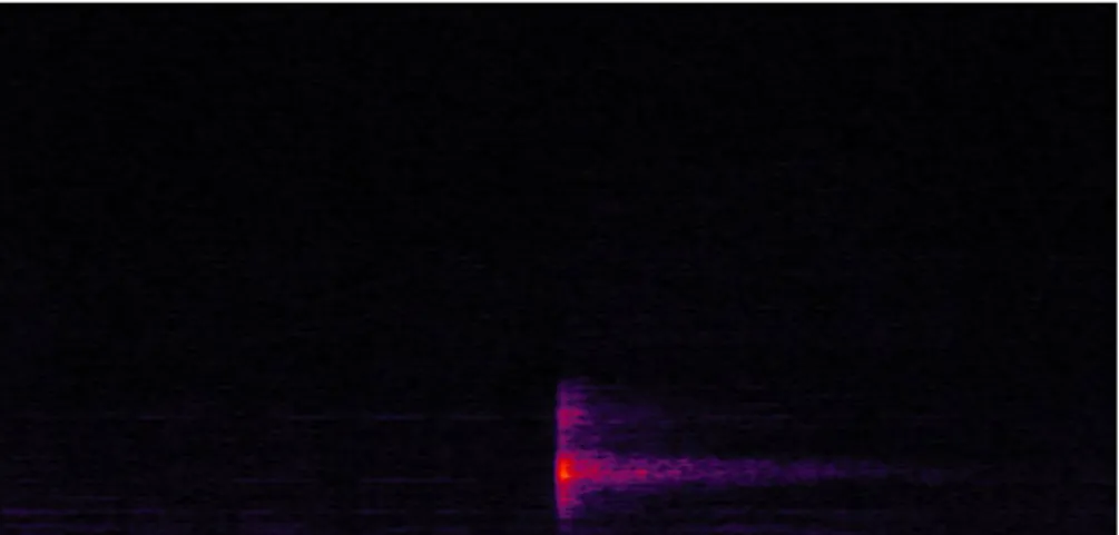
Due to the decorrelator, the envelope shape of the diffuse signal does not match to that of the direct signal. Here we use a simplest transient surround track called ‘knock’ to represent this problem. Figure 31 shows the spectrogram of the original knock wave file. Figure 9 and Figure 10 are the direct and the diffuse part of the knock wave file. We can find that the unmatched problem of the diffuse is very clear. Figure 8 The spectrogram of the knock signal wave Figure 9 The spectrogram of the direct part of the knock wave
15
Figure 10 The spectrogram of the diffuse part of the knock wave
Because of this envelope unmatched problem causing obvious temporal smearing of transient, MPS introduces the Subband Domain Temporal Processing (STP) shaping tool to solve this envelope unmatched problem. But the results of quality measurements after using STP are often worse than the ones without using STP. Hence, we point out some problems of using STP as follow. For the knock wave file, Figure 11 shows the modified diffuse part with using STP. Using STP shaping tool, we can find that transient smearing problem still exists. Figure 11 Spectrogram of diffuse part of the knock wave with using STP
Figure 12 Spectrogram of original unprocessed new_si026 Figure 13 Spectrogram of new_si026 by the CODEC in standard Figure 14 Spectrogram of new_si026 by using STP
17
From the spectrograms shown in Figure 12 ‐ 14, the contents on each band are also amplified obviously and the subjects of the subjective listening test would notice the difference of the volume and give worse grades on the ones using STP.
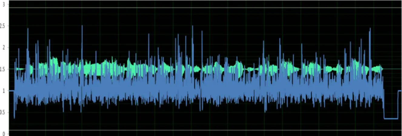
The reason that causes the sound volume to be amplified is that the scale factors calculated in STP are often larger than one. Figure 15 shows the si02.wav sound signal, represented by the green component, and the scale factors, indicated by the orange line, where the red horizontal line points out where the scale factor equals to 1.
Figure 15 The scale factors and the si02.wav sound signal using STP
In STP, the downmix processing that is used to make a downmix of the direct signal after the M2 matrix processing and the envelope estimation are the parts to affect the scale
factors. In STP, it uses the envelope estimation to calculate the scale factor for shaping diffuse signal, but some scale factors overflow unusually after doing shaping tool. Figure 16 shows the es01 wave signal, represented by the green component, and the scale factors, indicated by the blue line, are limited to 2.82 in the non‐transient parts.
Figure 16 The scale factors of es016 wave track by using shaping tool
Hence, this thesis proposes new procedures for shaping the diffuse signal with modifying the downmix process that is the fundamental basis of the shaping adjustment of the diffuse signal and the envelope estimation parts.
Chapter 4. Proposed Method
As shown is equation (15), the STP uses the downmix processing to directly sum the five channels of the direct signals and calculates the approximate energy of the direct signal and the scale factors. However, the meaning of this procedure is that STP adjusts the envelope of the diffuse signals to match the downmixed signal of the direct signals. In addition, there are some risks to downmix a signal like cancelling the contents of the signal. Because of the above statements, that is unreasonable to do the downmix processing in STP, hence the downmix processing must be removed. Figure 17 is the procedures of the modified STP.19 Figure 17 The modified STP without downmix process So the energy calculation after doing band‐pass filter is modified as: 2 , , , , ~nk k k ch direct k n ch direct z BP GF E , (31)
where the BPk and GFk are the same factors as shown in (17) and the calculations in following procedures are almost equal to the parts of the diffuse signal.
By removing the downmix process in STP, the fundamental basis of the shaping adjustment of the diffuse signal is not the downmixed signal of the direct signal any more. Each channel of the diffuse signal adjusts the shape to the relative channel of the direct signal. As a consequence, we can avoid the risks of doing downmix process and reduce the error of using downmixed signal of the direct signal to shape the diffuse signal.
As the problem mentioned in previous chapter, some scale factors in STP overflow unusually after doing shaping tool as Figure 16. That may cause a very serious effect on the final output sound track.
In STP, the envelope estimation is the main part of calculating the scale factors shown is (17) ‐ (22). STP uses the moving average to estimate the envelopes of the direct and diffuse signals. But there exists a known risk issue like error propagation between every sample,
which would influence the calculation of the scale factors directly as Figure 16.In order to
avoid this kind of risk issue, we replace envelope estimation by energy estimation. From Figure 18 – 20, the proposed method wants to fit the shape of the diffuse signal to that of the direct signal based on the ratio between each sample. If we do not do the shaping adjustment for the diffuse signal, the unprocessed diffuse signal will seriously destroy the final output signal with the unmatched shape.
Figure 18 The signal of the knock wave
21 Figure 19 The direct part signal of the knock wave Figure 20 The diffuse part signal of the knock wave without using STP The following are the steps for doing energy estimation. In the beginning, we calculate the energy of the direct and the diffuse signal after doing band‐pass filter as:
24 0 , , , k k n ch direct n ch direct E En and
24 0 , , , k k n ch diffuse n ch diffuse E En , (32) where the symbols nk ch diffuse E , , is the same as (17). After we have the energy of the direct and diffuse signals, there are two conditions based on the energy of diffuse signal. The first one is that if the energy of the diffuse signal is equal to zero, we do not need any process and set the scale factor to one shown as: 1 n ch scale . (33)The other is that if the energy of the diffuse signal does not equal to zero, we determine whether the energy of the diffuse signal of the previous time slot is zero or not. If so, the scale factor is set to one, and the energy of the direct and diffuse signal of the current time slot are saved for the calculation of the next time slot as below: n ch direct n ch direct
En
En
1 ,
, (34) n ch diffuse n ch diffuseEn
En
1 ,
, (35) If not, we would calculate the ratio of the energy of the direct signal between the previous and current time slots as: 1 , , n ch direct n ch direct n ch En En ratio , (36) where isa very small positive value. Then we used this ratio to calculate the scale factor for modifying the current energy of the diffuse signal as: n ch diffuse n ch n ch diffuse n ch En ratio En scale , 1 , . (37) Finally, the energy of the direct is saved as (34) and the modified energy of the diffuse signal of the current time slot are saved as below: n ch n ch diffuse n ch diffuse En scale En , 1 , . (38)By using the two modified procedures, remove downmix and energy estimation, we improve not only the accuracy of the scale factors but also the results of the objective quality assessments. We represent all the results between using proposed method and the original method in next chapter.
23
Chapter 5. Experiments and Results
All the proposed methods in the previous chapter are implemented on the MPEG Surround reference software. In this thesis, the objective quality experiments are evaluated by EAQUAL (Evaluation of Audio Quality) which simulates the perception of human ears. In this chapter, we introduce the MPEG Surround reference software, EAQUAL and what sound tracks we use. Finally, we show the results of the objective quality experiments by using the proposed methods and compare the differences between the original decoder and the proposed methods.
5.1. MPEG Surround Reference Software RM0
The reference software RM0 [11][12] is provided by the MPEG Surround standard committee. It was developed by Agere Systems, Coding Technologies, Fraunhofer IIS, and Philips and written in the C programming language for the codec ISO/IEC 23003‐1. Due to the MPEG Surround decoding processes are specifically defined, the reference software fully implements according to the decoding processes. But the encoding reference software only provides the simplest version that fits the required syntax on the specifications.
5.2. Quality Measurement
EAQUAL (Evaluation of Audio Quality) is a tool, which is the realization of BS.1387 for the objective quality assessment. The Objective Difference Grade (ODG) is the main output parameter from ‐4 to 0, ‐4 represents the worst case and 0 represents the best case, to simulate the perception by human ears.5.3. Test Tracks
For listening test, we use twelve stereo tracks and four surround tracks recommended by MPEG and listed in Table 1 and Table 2. Table 1 The twelve stereo tracks recommended by MPEG [13] Tracks Signal DescriptionSignals Mode Time (sec) Remark
1 es01 Vocal (Suzan Vega) stereo 10 (c)
2 es02 German speech stereo 8 (c)
3 es03 English speech stereo 7 (c)
4 sc01 Trumpet solo and orchestra stereo 10 (b) (d)
5 sc02 Orchestral piece stereo 12 (d)
6 sc03 Contemporary pop music stereo 11 (d)
7 si01 Harpsichord stereo 7 (b)
8 si02 Castanets stereo 7 (a)
9 si03 pitch pipe stereo 27 (b)
10 sm01 Bagpipes stereo 11 (b)
11 sm02 Glockenspiel stereo 10 (a) (b)
12 sm03 Plucked strings stereo 13 (a) (b)
Remark: (a) Transients. (b) Tonal/Harmonic structure. (c) Natural vocal (critical combination of tonal parts and attacks). (d) Complex sound.
25
Table 2 The four surround tracks [14]
No. Name Category LFE
channel
1 Stomp movie sound yes
2 rock_concert music
(back: ambience)
no
3 glock pathological &
ambience
no
4 pops music (back: direct) no
To correspond to the structure of the MPS encoder, all the stereo sequences must be extended to six‐channels by padding zeros in the C, Ls, Rs, and LFE channels.‘6’ is added behind the name of every stereo tracks to be the new name of them. Table 3 Detail information of the equipments Equipments Information Laptop CPU Intel(R) Core(TM)2 Duo CPU T8300 @ 2.40GHz Memory 4GB Sound Card Intel 82801H (ICH8 Family) HD Audio Controller OS Windows Vista Headphone Grado Alessandro Music Pro Headphone
5.4. Spectrum Comparison
Before representing the spectrum results, we should introduce the modified encoder and the two new surround sounds we made. Following are the details of the modified encoder and the two new surround sounds.
In MPS encoder, the original processing of the downmix is direct summation of the input signals to make the downmixed signal. But the energy of the downmixed signal does not equal the energy of input signal. To avoid the different energy of the downmixed signal transmitted from encoder effects the energy calculation in the shaping tool, the downmixed signal must be modified. So a proposed modified encoder [2] is used to solve this problem, it can ensure that the energy of the downmixed signal equals that of the input signal. For the two new surround sounds, first, we copy the L channel of the si02 to the other four channels except the LFE channel. Second, we make the L channel has one sample delay, the R channel has two samples delay, the Ls channel has three samples delay and the Rs channel has four samples delay. After the above two steps, we can get a transient type surround track called ‘new_si026.’ We can further make the other transient type surround sound track by using the new_si026. To avoid amplifying overflow, we make the dB of the new_si026 to be the 0.6 times first. Second, we let the left side channels (L and Ls) to be the 0.7 times than the C channel and the right side channels (R and Rs) to be the 1.5 times than the C channel. Finally, we can get the other transient type surround sound track ‘new_si026_scale.’ We use those two sequence to simulate the transient type surround sound for the experiements.
Figure 21 – 24 show the spectrograms results of new_si026 by using different procedures in decoder.
27 Figure 21 The spectrum of the L channel of original new_si026 Figure 22 The spectrum of the L channel of new_si026 by CODEC in standard without shaping tool Figure 23 The spectrum of the L channel of new_si026 by using proposed method
Figure 24 The spectrum of the L channel of new_si026 by using STP
Without using any shaping tool, Figure 22 shows that the transient smearing problem is in evidence. But if system uses STP shaping tool, the contents on each band are amplified obviously. By using proposed method, the transient smearing problem and the amplifying problem are solved efficiently.
5.5. Scale Factors Comparison
In section 3.3, Figure 16 shows the other problem causing the scale factors to unusually overflow. Figure 25 is the other case of the scale factors unusually overflow. Figure 25 The scale factors of sm026 wave track by using STP29
Figure 26 and Figure 27 are the two cases of scale factors by using the proposed method. We can find that the scale factors are all in a reasonable range for the proposed method processing. Figure 26 The scale factors of es016 wave track by using the proposed method Figure 27 The scale factors of sm026 wave track by using proposed method
5.6. Results of Objective Quality Measure
Figure 28 and Figure 29 are the results of the stereo and surround tracks objective quality assessments by EAQUAL where the nonSTP means the process without any shaping tool.
Figure 28 The ODGs for MPEG surround sequences by using 5151 tree structure
Figure 29 The ODGs for stereo sequences by using 5151 tree structure
31 For the above objective assessment results, we can find that there are no any destroyed effects for the non‐transient type sequences with using proposed method. Furthermore, we have an obvious quality improvement for the transient type surround tracks as new_si026 and new_si026_scale two wave files.
5.7. Results of Subjective Quality Measure
There are 10 subjects join this experiment and the results are shown in Figure 30. From the results of the subjective quality measurement, we still have improvement for the transient type sequences and without any destruction for the non‐transient type sequences.Figure 30 MUSHRA test on stereo tracks
5.8. TimeofUsage
For transient smearing problem, using proposed method for shaping diffuse signal can get an obvious improvement when the transient parts of two channels are very close in particular. It means that if the correlations between the transient parts of two channels are very high, the proposed method has the best quality. The followings are the experiments for verifying the above statements.
We use the followings steps to make knock surround track for the following experiments. First, we record the castanet with just one transient attack. Second, following the same procedures of making new_si026 can get the knock surround track. Figure 31 is the signal wave of knock. Figure 31 The knock signal wave In this case, 1, 2, 3 and 4 delays between channels, the followings show the results of the objective quality assessment and the spectrogram between using proposed method and the process without any shaping tool. Figure 32 The spectrum of the L channel of original knock
33 Figure 33 The spectrum of the L channel of knock by CODEC in standard without shaping tool Figure 34 The spectrum of the L channel of knock by using proposed method Figure 35 The ODGs for knock by using 5151 tree structure
Figure 32 – 34 are the final time signal and the spectrum results of using different processes and Figure 35 is the result of the objective quality assessment. Both of the results show that proposed method makes better results.
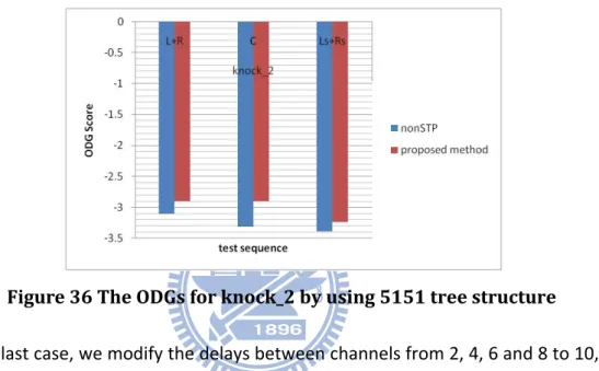
The second case has the same procedure as the first case expect the delay part. In this case, we modify the delays between channels from 1, 2, 3 and 4 to 2, 4, 6 and 8 delays respectively, and the outcome of the surround track based on this case is named as 'knock_2.' Figure 36 shows the result of the objective quality assessment. We can still get the improvements from the objective quality assessment from this case. However, the range of improvements is much smaller than the results of first case. Figure 36 The ODGs for knock_2 by using 5151 tree structure In the last case, we modify the delays between channels from 2, 4, 6 and 8 to 10, 20, 30 and 40 delays respectively, and the new outcome of the surround track is named as 'knock_10.'
35
Figure 37 shows the result of the objective quality assessment. In this case, we can find that there is no any benefit when using proposed method.
According to the verification the above experiments, using the proposed method for shaping diffuse signal can get an obvious improvement when the transient parts of two channels are very close.
Chapter 6. Conclusion and Future Work
For MPS decoder, the envelope shape of the diffuse signal after doing decorrelator process does not match the shape of the direct signal that causes the transient smearing problem. STP is used to solve this problem, but we find that it cannot solve this problem efficiently and it also causes destruction to the final output signal. This thesis has a contribution for designing a new shaping tool to solve the unmatched problem efficiently. Based on the results of the experiments, our proposed new shaping tool corrects the scale factors with more precise calculation and improves the result of the objective quality assessment. However, we just use the objective quality assessment to verify but we still need to do double verification through subjective listening test by MUSHRA [15][16] in the surround environment. For the experiment, the surround test sequences we made are all artificial with different delay. We should use the real surround sound recording system for recording a real surround track with transient to make the experiment result with higher completeness. Therefore, the above two issues are listed as future works.
37
References
[1] J. Breebaart, L. Villemoes, K. Kjorling, “Binaural rendering in MPEG Surround”, December, 2007.
[2] D.-P. Chen, H.-F. Hsiao, H.-W. Hsu, and C.-M. Liu, “Gram-Schmidt-based Downmixer and Decorrelator in the MPEG Surround Coding”, in Proc. AES 128th conv., London, UK, May 2010, preprint 8067.
[3] J. Herre, C. Faller, S. Disch, C. Ertel, J. Hilpert, A. Hoelzer, K. Linzmeier, C. Spenger and P. Kroon, “Spatial Audio Coding: Next-generation efficient and compatible coding of multi-channel audio”, in Proc. AES 117th conv., San Francisco, CA, USA, Oct. 2004, preprint 6186.
[4] Johannes Hilpert and Sascha Disch, “The MPEG Surround Audio Coding Standard”,
IEEE SIGNAL PROCESSING MAGAZINE, Jan. 2009.
[5] Information Technology MPEG Audio Technologies Part 1: MPEG Surround, ISO/IEC FDIS 23003-1, July 2006.
[6] J. Herre, K. Kjorling, J. Breebaart, C. Faller, S. Disch, H. Purnhagen, J. Koppens, J. Hilpert, J. Roden, W. Oomen, K. Linzmeier, and K. S. Chong, “MPEG Surround—The ISO/MPEG Standard for Efficient and Compatible Multichannel Audio Coding”, J. Audio
Eng. Soc., Vol. 56, No. 11, Nov. 2008.
[7] J. Breebaart, G. Hotho, J. Koppens, E. Schuijers, W. Oomen, and S. Van De Par, “Background, Concept and Architecture for the Recent MPEG Surround Standard on Multichannel Audio Compression”, J. Audio Eng. Soc., vol. 55, no. 5, pp. 331–351, May 2007.
[8] J. Breebaart and C. Faler, Spatial Audio Processing – MPEG Surround and Other
Applications. John Wiley & Sons, New York, 2007.
[9] J. Helve and James D. Johnston, “Enhancing the Performance of Perceptual Audio Coders by Using Temporal Noise Shaping (TNS)”, in Proc. AES 101th conv., Los Angeles, California, US, Nov. 1996, preprint 4384
[10] S. Disch, J. Herre, M. Neusinger, D. J. Breebaart and G. Hotho, “Temporal and Spatial Shaping of Multi-Channel Audio Signals”, Patent Application Publication, USA, 2007.
[11] ISO/IEC JTC1/SC29/WG11 (MPEG), Document N8636, “ISO/IEC
23003-1:2006/PDAM2, MPEG Surround reference software”, Oct. 2006
[12] ISO/IEC JTC1/SC29/WG11 (MPEG), document N11204, “ISO/IEC
23003-1:2007/Amd.2:2008/Cor.2, MPEG Surround reference software update”, Kyoto,
Japan, Jan., 2010
[13] S. H. Tang, C. M. Liu, and W. C. Lee, “Efficient Design of Time/Frequency Grid in HE-AAC Encoder”, Thesis for Master, 2006.
[14] J. Breebaart, J. Herre, C. Faller, J. Roden, F. Myburg, S. Disch, H. Purnhagen, G. Hotho, M. Neusinger, K. Kjorling, W. Oomen, “MPEG Spatial Audio Coding / MPEG Surround: Overview and Current Status”, in Proc. AES 119th conv., New York, USA, Oct. 2005. [15] PsyTel Multiple Codec Evaluation Software, http://www.psytel-research.co.yu.
[16] ITU Radio communication Sector BS.1116 (rev.1), “Methods for the Subjective Assessment of Small Impairments in Audio Systems Including Multichannel Sound Systems,” Geneva, 1997.
![Figure 3 MPS Encoder for 5151 and 5152 tree structures [6]](https://thumb-ap.123doks.com/thumbv2/9libinfo/8424854.180762/14.892.135.803.221.509/figure-mps-encoder-for-and-tree-structures.webp)
![Figure 6 The concept diagram of the decorrelator [8]](https://thumb-ap.123doks.com/thumbv2/9libinfo/8424854.180762/16.892.136.798.538.902/figure-the-concept-diagram-of-the-decorrelator.webp)
![Table 2 The four surround tracks [14]](https://thumb-ap.123doks.com/thumbv2/9libinfo/8424854.180762/34.892.213.727.112.391/table-the-four-surround-tracks.webp)