A - 1
SAFETY PRECAUTIONS
(Read these precautions before using.)
When using this product, thoroughly read this manual and the associated manuals introduced in this manual. Also pay careful attention to safety and handle the module properly.
The precautions given in this manual are concerned with this product only. Refer to the user's manual of the network system to use for a description of the network system safety precautions.
These SAFETY PRECAUTIONS are classified into two categories: "DANGER" and "CAUTION".
Depending on circumstances, procedures indicated by CAUTION may also be linked to serious results.
In any case, it is important to follow the directions for usage.
Store this manual in a safe place so that you can take it out and read it whenever necessary. Always forward it to the end user.
[DESIGN PRECAUTIONS]
DANGER
Createan interlock circuit on the program so that the system will operate safely based on the communication status information. Failure to do so may cause an accident due to an erroneous output or malfunction.
When an error occurs, all outputs are turned off in the MELSEC-ST system. (At default)
However, I/O operations of the head module and respective slice modules can be selected for the following errors:
(1) Communication error ( MELSEC-ST CC-Link Head Module User's Manual "4.3.1 Output status setting for module error")
(2) Slice module error
The output status for the case of an error can be set to Clear, Hold, or Preset with a command parameter of each slice module. (For whether the setting is available, refer to each slice module manual.)
Since the parameter is set to Clear by default, outputs will be turned off when an error occurs.
This parameter setting can be changed to Hold or Preset when the system safety is ensured by holding or presetting the output. ( Section 3.3.2 Combinations of various functions)
DANGER
CAUTION
Indicates that incorrect handling may cause hazardous conditions, resulting in death or severe injury.
Indicates that incorrect handling may cause hazardous conditions, resulting in medium or slight personal injury or physical damage.
A - 2
[DESIGN PRECAUTIONS]
[INSTALLATION PRECAUTIONS]
DANGER
Create an external failsafe circuit so that the MELSEC-ST system will operate safely, even when the external power supply or the system fails.
Failure to do so may cause an accident due to an erroneous output or malfunction.
(1) The status of output changes depending on the setting of various functions that control the output. Take sufficient caution when setting for those functions.
(2) Outputs may be kept ON or OFF due to malfunctions of output elements or the internal circuits.
For signals which may cause a serious accident, configure an external monitoring circuit.
CAUTION
Make sure to initialize the network system after changing parameters of the MELSEC-ST system or the network system. If unchanged data remain in the network system, this may cause malfunctions.
Do not install the control wires or communication cables together with the main circuit or power wires. Keep a distance of 100 mm (3.94 inch) or more between them. Not doing so could result in malfunctions due to noise.
At the time of power ON or OFF, a voltage or current may be instantaneously output from output terminals. Therefore, ensure stable analog outputs before starting the control.
CAUTION
Use the MELSEC-ST system in the general environment specified in the MELSEC-ST system users manual. Using this MELSEC-ST system in an environment outside the range of the general specifications could result in electric shock, fire, erroneous operation, and damage to or deterioration of the product.
Mount the head module and base module on the DIN rail securely (one rail for one module) referring to the MELSEC-ST system users manual and then fix them with stoppers. Incorrect mounting may result in a fall of the module, short circuits or malfunctions.
Secure the module with several stoppers when using it in an environment of frequent vibration.
Tighten the screws of the stoppers within the specified torque range. Undertightening can cause a drop, short circuit or malfunction. Overtightening can cause a drop, short circuit or malfunction due to damage to the screw or module.
A - 3 [INSTALLATION PRECAUTIONS]
[WIRING PRECAUTIONS]
CAUTION
Make sure to externally shut off all phases of the power supply for the whole system before mounting or removing a module. Failure to do so may damage the module.
(1) Online replacement of the power distribution module and/or the base module is not available.
When replacing either of the modules, shut off all phases of the external power supply.
Failure to do so may result in damage to all devices of the MELSEC-ST system.
(2) The I/O modules and the intelligent function modules can be replaced online.
Since online replacement procedures differ depending on the module type, be sure to make replacement as instructed.
For details, refer to the chapter of online module change in this manual.
Do not directly touch the module's conductive parts or electronic components. Doing so may cause malfunctions or failure of the module.
Make sure to securely connect each cable connector. Failure to do so may cause malfunctions due to poor contact.
DIN rail must be conductive; make sure to ground it prior to use. Failure to do so may cause electric shocks or malfunctions. Undertightening can cause a drop, short circuit or malfunction.
Overtightening can cause a drop, short circuit or malfunction due to damage to the screw or module.
DANGER
Completely turn off the external power supply when installing or placing wiring. Not completely turning off all power could result in electric shock or damage to the product.
CAUTION
Make sure to ground the control panel where the MELSEC-ST system is installed in the manner specified for the MELSEC-ST system. Failure to do so may cause electric shocks or malfunctions.
Use applicable solderless terminals and tighten them with the specified torque. If any solderless spade terminal is used, it may be disconnected when the terminal screw comes loose, resulting in failure.
Check the rated voltage and the terminal layout and wire the system correctly. Connecting an inappropriate power supply or incorrect wiring could result in fire or damage.
Tighten the terminal screws within the specified torque. If the terminal screws are loose, it could result in short circuits, fire, or erroneous operation. Overtightening may cause damages to the screws and/or the module, resulting in short circuits or malfunction.
A - 4
[WIRING PRECAUTIONS]
[STARTUP AND MAINTENANCE PRECAUTIONS]
CAUTION
Prevent foreign matter such as chips or wiring debris from entering the module. Failure to do so may cause fires, damage, or erroneous operation.
When connecting the communication and power supply cables to the module, always run them in conduits or clamp them. Not doing so can damage the module and cables by pulling a dangling cable accidentally or can cause a malfunction due to a cable connection fault.
When disconnecting the communication and power supply cables from the module, do not hold and pull the cable part. Pulling the cables connected to the module can damage the module and cables or can cause a malfunction due to a cable connection fault.
DANGER
Do not touch the terminals while power is on.
Doing so could cause shock or erroneous operation.
Make sure to shut off all phases of the external power supply for the system before cleaning the module or tightening screws.
Not doing so can cause the module to fail or malfunction.
CAUTION
Do not disassemble or modify the modules.
Doing so could cause failure, erroneous operation, injury, or fire.
Do not drop or give a strong impact to the module since its case is made of resin. Doing so can damage the module.
Make sure to shut off all phases of the external power supply for the system before mounting/
removing the module onto/from the control panel. Not doing so can cause the module to fail or malfunction.
Before handling the module, make sure to touch a grounded metal object to discharge the static electricity from the human body.
Failure to do say cause a failure or malfunctions of the module.
When using any radio communication device such as a cellular phone, keep a distance of at least 25cm (9.85 inch) away from the MELSEC-ST system.
Not doing so can cause a malfunction.
A - 5 [DISPOSAL PRECAUTIONS]
CAUTION
When disposing of this product, treat it as industrial waste.
A - 6
REVISIONS
* The manual number is given on the bottom left of the back cover.
Japanese Manual Version SH-080750-A
2008 MITSUBISHI ELECTRIC CORPORATION
Print Date * Manual Number Revision
Apr.,2008 SH(NA)-080756ENG-A First edition
This manual confers no industrial property rights or any rights of any other kind, nor does it confer any patent licenses.
Mitsubishi Electric Corporation cannot be held responsible for any problems involving industrial property rights which may occur as a result of using the contents noted in this manual.
A - 7
INTRODUCTION
Thank you for choosing the ST1DA2-V/ST1DA1-I/ST1DA2-V-F01/ST1DA1-I-F01 MELSEC-ST digital- analog converter module.
Before using the module, please read this manual carefully to fully understand the functions and performance of the ST1DA2-V/ST1DA1-I/ST1DA2-V-F01/ST1DA1-I-F01 MELSEC-ST digital-analog converter module and use it correctly.
CONTENTS
SAFETY PRECAUTIONS•••••••••••••••••••••••••••••••••••••••••••••••••••••••••••••••••••••••••••••••••••••••••••••••••••••• A - 1 REVISIONS••••••••••••••••••••••••••••••••••••••••••••••••••••••••••••••••••••••••••••••••••••••••••••••••••••••••••••••••••••••• A - 6 INTRODUCTION •••••••••••••••••••••••••••••••••••••••••••••••••••••••••••••••••••••••••••••••••••••••••••••••••••••••••••••••• A - 7 CONTENTS••••••••••••••••••••••••••••••••••••••••••••••••••••••••••••••••••••••••••••••••••••••••••••••••••••••••••••••••••••••• A - 7 ABOUT MANUALS ••••••••••••••••••••••••••••••••••••••••••••••••••••••••••••••••••••••••••••••••••••••••••••••••••••••••••••• A - 10 Compliance with the EMC and Low Voltage Directives ••••••••••••••••••••••••••••••••••••••••••••••••••••••••••••••••• A - 10 HOW TO READ MANUAL •••••••••••••••••••••••••••••••••••••••••••••••••••••••••••••••••••••••••••••••••••••••••••••••••••• A - 11 ABOUT THE GENERIC TERMS AND ABBREVIATIONS•••••••••••••••••••••••••••••••••••••••••••••••••••••••••••••• A - 13 TERM DEFINITION •••••••••••••••••••••••••••••••••••••••••••••••••••••••••••••••••••••••••••••••••••••••••••••••••••••••••••• A - 14 Packing list ••••••••••••••••••••••••••••••••••••••••••••••••••••••••••••••••••••••••••••••••••••••••••••••••••••••••••••••••••••••• A - 15
CHAPTER1 OVERVIEW 1 - 1 to 1 - 2
1.1 Features ••••••••••••••••••••••••••••••••••••••••••••••••••••••••••••••••••••••••••••••••••••••••••••••••••••••••••••••1 - 1
CHAPTER2 SYSTEM CONFIGURATION 2 - 1 to 2 - 3
2.1 Overall Configuration•••••••••••••••••••••••••••••••••••••••••••••••••••••••••••••••••••••••••••••••••••••••••••••••2 - 1 2.2 Applicable System ••••••••••••••••••••••••••••••••••••••••••••••••••••••••••••••••••••••••••••••••••••••••••••••••••2 - 2 2.2.1 Applicable head module •••••••••••••••••••••••••••••••••••••••••••••••••••••••••••••••••••••••••••••••••••••2 - 2 2.2.2 Applicable base module••••••••••••••••••••••••••••••••••••••••••••••••••••••••••••••••••••••••••••••••••••••2 - 2 2.2.3 Applicable coding element ••••••••••••••••••••••••••••••••••••••••••••••••••••••••••••••••••••••••••••••••••2 - 2 2.2.4 Applicable software package •••••••••••••••••••••••••••••••••••••••••••••••••••••••••••••••••••••••••••••••2 - 2 2.3 Precautions for System Configuration ••••••••••••••••••••••••••••••••••••••••••••••••••••••••••••••••••••••••••2 - 3 2.4 Checking Hardware and Software Versions •••••••••••••••••••••••••••••••••••••••••••••••••••••••••••••••••••2 - 3
CHAPTER3 SPECIFICATIONS 3 - 1 to 3 - 16
3.1 Performance Specifications•••••••••••••••••••••••••••••••••••••••••••••••••••••••••••••••••••••••••••••••••••••••3 - 1 3.2 I/O Conversion Characteristics•••••••••••••••••••••••••••••••••••••••••••••••••••••••••••••••••••••••••••••••••••3 - 2 3.2.1 Output characteristics of ST1DA2-V•••••••••••••••••••••••••••••••••••••••••••••••••••••••••••••••••••••••3 - 3 3.2.2 Output characteristics of ST1DA1-I••••••••••••••••••••••••••••••••••••••••••••••••••••••••••••••••••••••••3 - 4 3.2.3 Relation between offset/gain setting and analog output value •••••••••••••••••••••••••••••••••••••••3 - 5 3.2.4 Accuracy ••••••••••••••••••••••••••••••••••••••••••••••••••••••••••••••••••••••••••••••••••••••••••••••••••••••••3 - 5 3.2.5 Conversion speed •••••••••••••••••••••••••••••••••••••••••••••••••••••••••••••••••••••••••••••••••••••••••••••3 - 6 3.2.6 Intelligent function module processing time ••••••••••••••••••••••••••••••••••••••••••••••••••••••••••••••3 - 6 3.3 Function•••••••••••••••••••••••••••••••••••••••••••••••••••••••••••••••••••••••••••••••••••••••••••••••••••••••••••••••3 - 7
A - 8
3.3.1 Function list•••••••••••••••••••••••••••••••••••••••••••••••••••••••••••••••••••••••••••••••••••••••••••••••••••••3 - 7 3.3.2 Combinations of various functions •••••••••••••••••••••••••••••••••••••••••••••••••••••••••••••••••••••••••3 - 9 3.4 I/O Data ••••••••••••••••••••••••••••••••••••••••••••••••••••••••••••••••••••••••••••••••••••••••••••••••••••••••••••• 3 - 11 3.4.1 Bit Input Area••••••••••••••••••••••••••••••••••••••••••••••••••••••••••••••••••••••••••••••••••••••••••••••••• 3 - 12 3.4.2 Bit output area ••••••••••••••••••••••••••••••••••••••••••••••••••••••••••••••••••••••••••••••••••••••••••••••• 3 - 13 3.4.3 Word output area •••••••••••••••••••••••••••••••••••••••••••••••••••••••••••••••••••••••••••••••••••••••••••• 3 - 14 3.5 Memory and Parameters •••••••••••••••••••••••••••••••••••••••••••••••••••••••••••••••••••••••••••••••••••••••• 3 - 15 3.5.1 Memory•••••••••••••••••••••••••••••••••••••••••••••••••••••••••••••••••••••••••••••••••••••••••••••••••••••••• 3 - 15 3.5.2 Parameters ••••••••••••••••••••••••••••••••••••••••••••••••••••••••••••••••••••••••••••••••••••••••••••••••••• 3 - 16
CHAPTER4 SETUP AND PROCEDURES BEFORE OPERATION 4 - 1 to 4 - 14
4.1 Handling Precautions ••••••••••••••••••••••••••••••••••••••••••••••••••••••••••••••••••••••••••••••••••••••••••••••4 - 1 4.2 Setup and Procedure before Operation ••••••••••••••••••••••••••••••••••••••••••••••••••••••••••••••••••••••••4 - 2 4.3 Part Names ••••••••••••••••••••••••••••••••••••••••••••••••••••••••••••••••••••••••••••••••••••••••••••••••••••••••••4 - 3 4.3.1 Status confirmation by LED indicators ••••••••••••••••••••••••••••••••••••••••••••••••••••••••••••••••••••4 - 4 4.4 Wiring •••••••••••••••••••••••••••••••••••••••••••••••••••••••••••••••••••••••••••••••••••••••••••••••••••••••••••••••••4 - 5 4.4.1 Wiring precautions ••••••••••••••••••••••••••••••••••••••••••••••••••••••••••••••••••••••••••••••••••••••••••••4 - 5 4.4.2 External wiring •••••••••••••••••••••••••••••••••••••••••••••••••••••••••••••••••••••••••••••••••••••••••••••••••4 - 6 4.5 Offset/Gain Settings ••••••••••••••••••••••••••••••••••••••••••••••••••••••••••••••••••••••••••••••••••••••••••••••••4 - 8
CHAPTER5 GX Configurator-ST 5 - 1 to 5 - 12
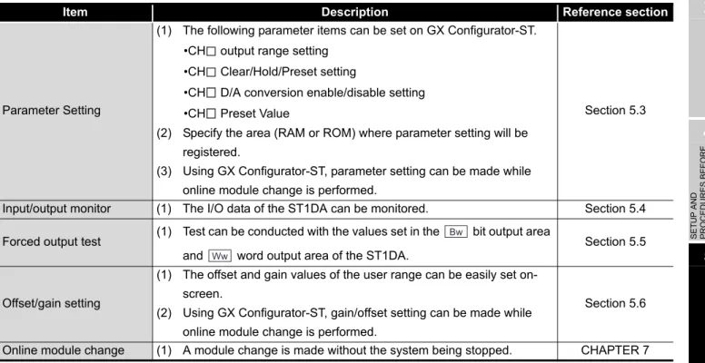
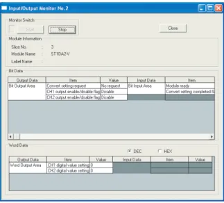
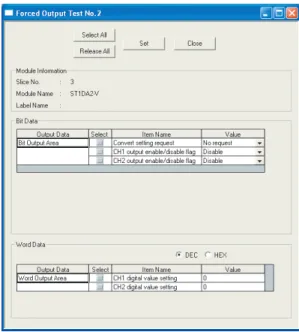
5.1 GX Configurator-ST Functions •••••••••••••••••••••••••••••••••••••••••••••••••••••••••••••••••••••••••••••••••••5 - 1 5.2 Creating a project •••••••••••••••••••••••••••••••••••••••••••••••••••••••••••••••••••••••••••••••••••••••••••••••••••5 - 2 5.3 Parameter Setting•••••••••••••••••••••••••••••••••••••••••••••••••••••••••••••••••••••••••••••••••••••••••••••••••••5 - 3 5.4 Input/Output Monitor••••••••••••••••••••••••••••••••••••••••••••••••••••••••••••••••••••••••••••••••••••••••••••••••5 - 6 5.5 Forced Output Test •••••••••••••••••••••••••••••••••••••••••••••••••••••••••••••••••••••••••••••••••••••••••••••••••5 - 8 5.6 Offset/Gain Setting ••••••••••••••••••••••••••••••••••••••••••••••••••••••••••••••••••••••••••••••••••••••••••••••• 5 - 10
CHAPTER6 PROGRAMMING 6 - 1 to 6 - 22
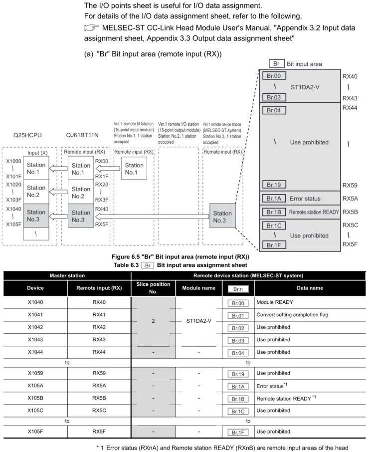
6.1 Programming Procedure ••••••••••••••••••••••••••••••••••••••••••••••••••••••••••••••••••••••••••••••••••••••••••6 - 1 6.2 System Configuration Example ••••••••••••••••••••••••••••••••••••••••••••••••••••••••••••••••••••••••••••••••••6 - 3 6.3 Settings and Communication Data ••••••••••••••••••••••••••••••••••••••••••••••••••••••••••••••••••••••••••••••6 - 4 6.4 Program Examples •••••••••••••••••••••••••••••••••••••••••••••••••••••••••••••••••••••••••••••••••••••••••••••••••6 - 8
CHAPTER7 ONLINE MODULE CHANGE 7 - 1 to 7 - 13
7.1 Precautions for Online Module Change ••••••••••••••••••••••••••••••••••••••••••••••••••••••••••••••••••••••••7 - 1 7.2 Preparations for Online Module Change •••••••••••••••••••••••••••••••••••••••••••••••••••••••••••••••••••••••7 - 4 7.3 Disconnecting/connecting the External Device for Online Module Change •••••••••••••••••••••••••••••7 - 5 7.4 Online Module Change Procedure ••••••••••••••••••••••••••••••••••••••••••••••••••••••••••••••••••••••••••••••7 - 6 7.4.1 When parameter setting or offset/gain setting is performed using GX Configurator-ST during online module change ••••••••••••••••••••••••••••••••••••••••••••••••••••••••••••••••••••••••••••••••••••••••••••••••7 - 6
A - 9
CHAPTER8 COMMANDS 8 - 1 to 8 - 50
8.1 Command List •••••••••••••••••••••••••••••••••••••••••••••••••••••••••••••••••••••••••••••••••••••••••••••••••••••••8 - 1 8.2 Common Commands•••••••••••••••••••••••••••••••••••••••••••••••••••••••••••••••••••••••••••••••••••••••••••••••8 - 3 8.2.1 Operating status read request (Command No. : 8100H/0100H) •••••••••••••••••••••••••••••••••••••8 - 3 8.2.2 Error code read request (Command No.: 8101H/0101H) •••••••••••••••••••••••••••••••••••••••••••••8 - 6 8.3 Initial Data Write Command•••••••••••••••••••••••••••••••••••••••••••••••••••••••••••••••••••••••••••••••••••••••8 - 9 8.3.1 Initial data batch write request (Command No.: 8106H)•••••••••••••••••••••••••••••••••••••••••••••••8 - 9 8.3.2 Initial data individual write request (Command No.: 8107H/0107H)••••••••••••••••••••••••••••••• 8 - 12 8.4 ST1DA Parameter Setting Read Commands ••••••••••••••••••••••••••••••••••••••••••••••••••••••••••••••• 8 - 16 8.4.1 D/A conversion enable/disable setting read (Command No. : 9200H/1200H) •••••••••••••••••• 8 - 16 8.4.2 CH[ ] preset value read (Command No.: 9201H, 9202H/1201H, 1202H) •••••••••••••••••••••••• 8 - 19 8.4.3 Output range set value read (Command No.: 9209H/1209H) •••••••••••••••••••••••••••••••••••••• 8 - 22 8.5 ST1DA Parameter Setting Write Commands•••••••••••••••••••••••••••••••••••••••••••••••••••••••••••••••• 8 - 25 8.5.1 D/A conversion enable/disable setting (Command No.: A200H/2200H) ••••••••••••••••••••••••• 8 - 25 8.5.2 CH[ ] preset value write (Command No.: A201H, A202H/2201H, 2202H) ••••••••••••••••••••••• 8 - 28 8.6 ST1DA Control Commands ••••••••••••••••••••••••••••••••••••••••••••••••••••••••••••••••••••••••••••••••••••• 8 - 31 8.6.1 Parameter setting read from ROM (Command No.:B200H/3200H) ••••••••••••••••••••••••••••••• 8 - 31 8.6.2 Parameter setting write to ROM (Command No.: B201H/3201H) ••••••••••••••••••••••••••••••••• 8 - 34 8.6.3 Operation mode setting (Command No.: B202H/3202H) ••••••••••••••••••••••••••••••••••••••••••• 8 - 37 8.6.4 Offset channel specification (Command No.: B203H/3203H) •••••••••••••••••••••••••••••••••••••• 8 - 40 8.6.5 Gain channel specification (Command No.: B204H/3204H) •••••••••••••••••••••••••••••••••••••••• 8 - 43 8.6.6 User range write (Command No.: B205H/3205H) •••••••••••••••••••••••••••••••••••••••••••••••••••• 8 - 46 8.7 Values Stored into Command Execution Result •••••••••••••••••••••••••••••••••••••••••••••••••••••••••••• 8 - 49
CHAPTER9 TROUBLESHOOTING 9 - 1 to 9 - 6
9.1 Error Code List ••••••••••••••••••••••••••••••••••••••••••••••••••••••••••••••••••••••••••••••••••••••••••••••••••••••9 - 1 9.2 Troubleshooting •••••••••••••••••••••••••••••••••••••••••••••••••••••••••••••••••••••••••••••••••••••••••••••••••••••9 - 3 9.2.1 When the RUN LED is flashing or turned off•••••••••••••••••••••••••••••••••••••••••••••••••••••••••••••9 - 3 9.2.2 When the RUN LED is on and the ERR. LED is on or flashing ••••••••••••••••••••••••••••••••••••••9 - 4 9.2.3 When an analog output value is not output ••••••••••••••••••••••••••••••••••••••••••••••••••••••••••••••9 - 5
APPENDIXES App - 1 to App - 4
Appendix 1 Accessories ••••••••••••••••••••••••••••••••••••••••••••••••••••••••••••••••••••••••••••••••••••••••••••• App - 1 Appendix 2 Specification Comparisons between Hardware Versions •••••••••••••••••••••••••••••••••••••• App - 2 Appendix 3 External Dimensions •••••••••••••••••••••••••••••••••••••••••••••••••••••••••••••••••••••••••••••••••• App - 3
INDEX INDEX - 1 to INDEX - 2
A - 10
ABOUT MANUALS
The following manuals are related to this product.
Referring to this list, please request the necessary manuals.
Compliance with the EMC and Low Voltage Directives
(1) For MELSEC-ST system
To configure a system meeting the requirements of the EMC and Low Voltage Directives when incorporating the Mitsubishi MELSEC-ST system (EMC and Low Voltage Directives compliant) into other machinery or equipment, refer to Chapter 11
"EMC and Low Voltage Directives" of the MELSEC-ST System User's Manual.
The CE mark, indicating compliance with the EMC and Low Voltage Directives, is printed on the rating plate of the MELSEC-ST system.
(2) For this product
No additional measures are necessary for the compliance of this product with the EMC and Low Voltage Directives.
Relevant Manuals
Manual Name Manual Number
(Model Code) MELSEC-ST System User's Manual
Explains the system configuration of the MELSEC-ST system and the performance specifications, functions, handling, wiring and troubleshooting of the power distribution modules, base modules and I/O modules.
(Sold separately)
SH-080456ENG (13JR72)
MELSEC-ST CC-Link Head Module User's Manual
Explains the system configuration, specifications, functions, handling, wiring and troubleshooting of the ST1H-BT.
(Sold separately)
SH-080754ENG-A (13JZ11)
GX Configurator-ST Version 1 Operating Manual
Explains how to operate GX Configurator-ST, how to set the intelligent function module parameters, and how to monitor the MELSEC-ST system.
(Sold separately)
SH-080439ENG (13JU47)
CC-Link System Master/Local Module User's Manual
Describes the system configurations, performance specifications, functions, handling, wiring and troubleshooting of the QJ61BT11N.
(Sold separately)
SH080394E (13JR64)
A - 11
HOW TO READ MANUAL
This manual explains each area for the CC-Link remote I/O. remote registers, and message transmission using , , , , , and .
(1) Data symbol
Br Wr Cr Bw Ww Cw
Terminating resistor
Output status
Input status
G.RDMSG
Master station Remote device station (MELSEC-ST system)
Programmable controller CPU Master module
Message transmission Device
Device Command execution area
Command result area
Head module Slice
module
Slice module
Remote input (RX) Bit input area
Word input
Bit output area Remote register (RWr)
Remote output (RY)
Remote register (RWw) Word output area
Command execution
Command result
CC-Link Terminating resistor
Head module
Remote input (RX)
Remote register (RWr)
Remote output (RY)
Remote register (RWw) Cw
Cr
( (2) Head module Master station, (3) Master station Head module)
Cr. (7-0) 0
<Example of Command result area>
Abbreviated data symbol Range Cr
Detail data No.
When the unit of data is one word (16 bits), the corresponding bits are indicated.
(0): Bit 0 (7-0): Range of bit 0 to bit 7
A - 12
(2) Head module Master station
(a) Remote input (RX)(b) Remote register (RWr)
(c) Message transmission
(3) Master station Head module
(a) Remote output (RY)(b) Remote register (RWw)
(c) Message transmission
Data symbol Area Unit Detail data No. notation
to Bit Input Area 1 bit/symbol Hexadecimal
Data symbol Area Unit Detail data No. notation
to Word Input Area 1 word/symbol Hexadecimal
Data symbol Area Unit Detail data No. notation
to Command Result Area 1 word/symbol Decimal
Data symbol Area Unit Detail data No. notation
to Bit Input Area 1 bit/symbol Hexadecimal
Data symbol Area Unit Detail data No. notation
to Word Input Area 1 word/symbol Hexadecimal
Data symbol Area Unit Detail data No. notation
to Command Result Area 1 word/symbol Decimal
Br Br.00 Br.n
Wr Wr.00 Wr.n
Cr Cr.0 Cr.n
Bw Bw.00 Bw.n
Ww Wn.00 Wn.n
Cw Cn.0 Cn.n
A - 13
ABOUT THE GENERIC TERMS AND ABBREVIATIONS
This manual uses the following generic terms and abbreviations to describe the ST1DA, unless otherwise specified.
Generic Term/Abbreviation Description
ST1DA2-V General term for ST1DA2-V and ST1DA2-V-F01 MELSEC-ST digital-analog converter modules.
ST1DA2-V-F01 Abbreviation for ST1DA2-V-F01 type MELSEC-ST digital-analog converter module.
ST1DA1-I General term for ST1DA1-I and ST1DA1-I-F01 MELSEC-ST digital-analog converter modules.
ST1DA1-I-F01 Abbreviation for ST1DA1-I-F01 MELSEC-ST digital-analog converter module.
ST1DA Generic term for ST1DA2-V and ST1DA1-I.
Head module Abbreviation for the ST1H-BT MELSEC-ST CC-Link head module.
Bus refreshing module Module that distributes external system power and auxiliary power to the head module and slice modules.
Power feeding module Module that distributes external auxiliary power to slice modules.
Power distribution module Generic term for the bus refreshing module and power feeding module.
Base module Generic term for a module that transfers data between the head module and slice module, and between the slice module and external devices (including wiring).
Input module Generic term for modules that handle input data in units of bits.
Output module Generic term for modules that handle output data in units of bits.
Intelligent function module Generic term for modules that handle input/output data in units of words.
I/O module Generic term for input modules and output modules.
Slice module Generic term for power distribution modules, I/O modules, and intelligent function modules that can be mounted on a base module.
MELSEC-ST system Generic term for a system that is composed of a head module, slice modules, an end plate and end brackets.
GX Configurator-ST Configuration software dedicated to the MELSEC-ST system.
The general name of SWnD5C-STPB-E type products.(n=1 or later) CC-Link Abbreviation for Control and Communication Link system.
Master module Abbreviation for the QJ61BT11N when it is used as a master station.
RDMSG Abbreviation for dedicated instruction of master station.
A - 14
TERM DEFINITION
The following explains the meanings and definitions of the terms used in this manual.
Term Definition
Cyclic transmission A communication method by which remote I/O data and remote register data are transferred periodically.
Message transmission A transmission method for writing parameters from the master station to a remote device station and reading the remote device station status.
Master station This station controls the entire data link system.
One master station is required for one system.
Remote I/O station A remote station that can only use bit data. (Input from or output to external devices) (AJ65BTB1-16D, AJ65SBTB1-16D, etc.)
Remote device station
A remote station that can use both bit and word data. (Input from or output to external devices, or analog data conversion)
(ST1H-BT, AJ65BT-64AD, AJ65BT-64DAV, AJ65BT-64AI, etc.)
SB
Link special relay (for CC-Link).
Bit data that indicate the module operating status and data link status of the master/local station.
SW
Link special register (for CC-Link).
Data in units of 16 bits, which indicate the module operating status and data link status of the master/local station.
RX Remote input (for CC-Link).
Bit data that are input from remote stations to the master station.
RY Remote output (for CC-Link)
Bit data that are output from the master station to remote stations.
RWr Remote register. (CC-Link data read area)
16-bit word data that are input from remote device stations to the master station.
RWw Remote register. (CC-Link data write area)
16-bit word data that are output from the master station to remote device stations.
Remote net Ver.1 mode Select this mode when extended cyclic setting is not needed or when the QJ61BT11 is replaced with the QJ61BT11N.
Remote net Ver.2 mode Select this mode when creating a new system with extended cyclic setting.
I/O data Data that are sent/received between the head module and the master station.
Generic term for RX, RY, RWr, and RWw.
bit input area Bit input data of each module.
Input data are sent from the head module to the master station through the remote input (RX).
bit output area
Bit output data of each module.
Output data are sent from the master station to the head module through the remote output (RY).
word input area
Word (16-bit) input data of an intelligent function module.
Input data are sent from the head module to the master station through the remote register (RWr).
word output area
Word (16-bit) output data of an intelligent function module.
Output data are sent from the master station to the head module through the remote register (RWw).
command result area
An area for the information that indicates a command result.
This information is stored in Setting data ((D1)+1 and after) of the RDMSG instruction of the master station.
command execution area
An area for the information for executing a command.
This information is stored in Setting data ((S2)+1 and after) of the RDMSG instruction of the master station.
Br.n
Bw.n
Wr.n
Ww.n
Cr.n
Cw.n
A - 15
Packing list
One of the following ST1DA products is included.
Number of occupied I/O points
The area, that is equivalent to the occupied I/O points, is occupied in bit input area/
bit output area.
Slice No.
The number assigned to every 2 occupied I/O points of each module. The numbers are assigned in ascending order, starting from "0" of the head module. (The maximum value is 127.)
This is used for specifying a command execution target.
Slice position No.
The number that shows where the slice module is physically installed.
The numbers are assigned in ascending order, starting from "0" of the head module. (The maximum value is 63.)
This is used for specifying a command execution target.
Start slice No. The start slice No. assigned to the head module and slice modules.
Command Generic term for requests that are executed by the master station for reading each module's operation status, setting intelligent function module command parameters or various controls.
Command parameter Generic term for parameters set in commands or GX Configurator-ST.
All of the parameters set for the head module and slice modules are command parameters.
Model name Product name Quantity
ST1DA2-V ST1DA2-V MELSEC-ST digital-analog converter module 1
ST1DA1-I ST1DA1-I MELSEC-ST digital-analog converter module 1
ST1DA2-V-F01 ST1DA2-V-F01 MELSEC-ST digital-analog converter module 1
ST1DA1-I-F01 ST1DA1-I-F01 MELSEC-ST digital-analog converter module 1
Term Definition
Br Bw
1 - 1
1.1 Features1 OVERVIEW
CHAPTER1 OVERVIEW
This User's Manual provides the specifications, handling, programming methods, etc. for the ST1DA2-V and ST1DA2-V-F01 MELSEC-ST digital-analog converter modules (hereinafter referred to as the ST1DA2-V) and ST1DA1-I and ST1DA1-I-F01 MELSEC-ST digital-analog converter modules (hereinafter referred to as the ST1DA1-I).
In this manual, the ST1DA2-V, ST1DA2-V-F01, ST1DA1-I, and ST1DA1-I-F01 are collectively referred to as the ST1DA.
This manual describes only the ST1DA.
For information on the MELSEC-ST system, refer to the following manual.
MELSEC-ST System User's Manual
Remark
Only the differences between the ST1DA2-V and ST1DA2-V-F01 and between the ST1DA1-I and ST1DA1-I-F01 are default values of the D/A conversion enable/
disable function. ( Section 3.3.1 Function list)
• ST1DA2-V and ST1DA1-I: D/A conversion disabled for channels
• ST1DA2-V-F01 and ST1DA1-I-F01: D/A conversion enabled for all channels
1.1 Features
(1) Available models
• ST1DA2-V···2-channel voltage output type.
• ST1DA1-I···1-channel current output type.
(2) Up to 26 modules can be mounted
For one head module, up to 26 ST1DA modules (ST1DA2-V: 52 channels, ST1DA1-I:
26 channels) can be mounted.
(3) Output range can be changed for each channel
The analog output range*1 can be changed for each channel to change the I/O conversion characteristic.
* 1 The output range refers to the type of offset/gain settings. The most frequently used range is set as the default, but the user can make offset/gain settings according to the purpose.
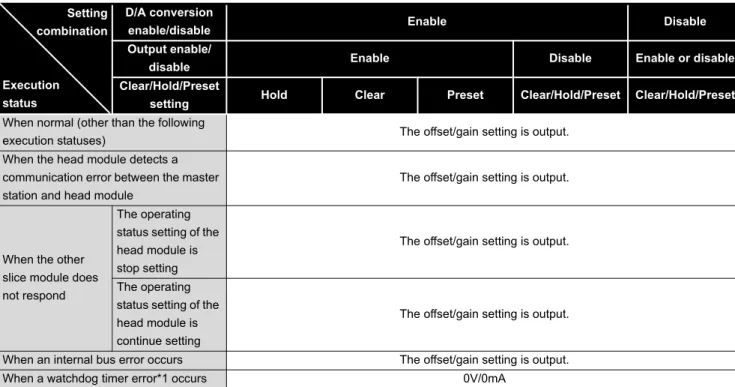
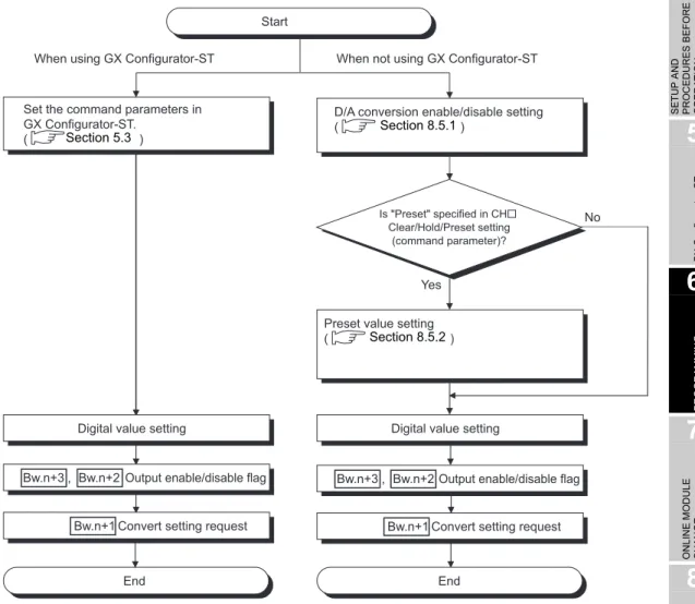
(4) Clear/Hold/Preset functions
The analog output provided at a communication error or module fault can be selected.
( Section 3.3.2 Combinations of various functions)
• Clear : Outputs an offset value.
• Hold : Holds the latest analog value output from each channel.
• Preset : Outputs the preset value.
(5) Command function
By writing command parameters to the ROM using a command, D/A conversion can be made without setting the command parameters at a module start (power-on).
1 OVERVIEW
1.1 Features
1 - 2 1
OVERVIEW
2
SYSTEM CONFIGURATION
3
SPECIFICATIONS
4
SETUP AND PROCEDURES BEFORE OPERATION
5
GX Configurator-ST
6
PROGRAMMING
7
ONLINE MODULE CHANGE
8
COMMANDS
(6) High-speed conversion processing
Conversion processing is performed at a speed of 0.1ms/channel.
(7) High accuracy
This module performs D/A conversion at the accuracy of 0.8% relative to the maximum analog output value.
(8) Online module change
The module can be changed without the system being stopped.
(9) Easy settings using the GX Configurator-ST
The optional software package (GX Configurator-ST) is available.
GX Configurator-ST is not necessarily required for the system.
However, using GX Configurator-ST, allows on-screen parameter setting and offset/
gain setting, which reduces programs of master station and makes the setting/
operating status check easier.
2 - 1
2.1 Overall Configuration2 SYSTEM CONFIGURATION
CHAPTER2 SYSTEM CONFIGURATION
This chapter describes the system configuration for use of the ST1DA.
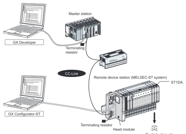
2.1 Overall Configuration
The overall configuration for use of the ST1DA is shown below.
Figure 2.1 Overall system configuration GX Developer
GX Configurator-ST
Terminating resistor
CC-Link
Terminating resistor Master station
Control valve, etc.
ST1DA Remote device station (MELSEC-ST system)
Head module
2 SYSTEM CONFIGURATION
2.2 Applicable System
2.2.1 Applicable head module
2 - 2 1
OVERVIEW
2
SYSTEM CONFIGURATION
3
SPECIFICATIONS
4
SETUP AND PROCEDURES BEFORE OPERATION
5
GX Configurator-ST
6
PROGRAMMING
7
ONLINE MODULE CHANGE
8
COMMANDS
2.2 Applicable System
This section explains the applicable system.
2.2.1 Applicable head module
The head module applicable to the ST1DA is indicated below.
2.2.2 Applicable base module
The base modules applicable to the ST1DA are indicated below.
2.2.3 Applicable coding element
The coding elements applicable for the ST1DA are indicated below.
The coding element is fitted before shipment.
It is also available as an option in case it is lost.
2.2.4 Applicable software package
he software package applicable to the ST1DA is indicated below.
* 1 GX Configurator-ST is optional.
Table 2.1 Applicable head module
Product name Model name
MELSEC-ST CC-Link Head Module ST1H-BT
Table 2.2 Applicable base module
Type Model name
Spring Clamp Type ST1B-S4IR2
Screw Clamp Type ST1B-E4IR2
Table 2.3 Applicable coding element
Description Model name
Coding element for ST1DA2-V or
ST1DA2-V-F01 ST1A-CKY-11
Coding element for ST1DA1-I or
ST1DA1-I-F01 ST1A-CKY12
Table 2.4 Applicable software package
Product name model name Supported Version
GX Configurator-ST*1 SW1D5C-STPB-E Ver.1.06G or later
2 - 3
2.3 Precautions for System Configuration 2.2.4 Applicable software package2 SYSTEM CONFIGURATION
2.3 Precautions for System Configuration
For precautions for ST1DA system configuration, refer to the following.
MELSEC-ST System User's Manual, "3.4 Precautions for System Configuration"
2.4 Checking Hardware and Software Versions
The hardware and software versions of the ST1DA can be checked on the DATE section on the rating plate, which is situated on the side of the module.
Figure 2.2 Rating plate
PASSED
MODEL
DATE
MADE IN JAPAN Comformed standard
Software version Hardware version
* * * * A A * *
8th7th6th5th4th3rd2nd1st
3 SPECIFICATIONS
3.1 Performance Specifications
3 - 1 1
OVERVIEW
2
SYSTEM CONFIGURATION
3
SPECIFICATIONS
4
SETUP AND PROCEDURES BEFORE OPERATION
5
GX Configurator-ST
6
PROGRAMMING
7
ONLINE MODULE CHANGE
8
COMMANDS
CHAPTER3 SPECIFICATIONS
This chapter provides the specifications of the ST1DA.
For the general specifications of the ST1DA, refer to the following manual.
MELSEC-ST System User's Manual
3.1 Performance Specifications
Table 3.1 indicates the general specifications of the ST1DA.
Table 3.1 Performance specifications list
Item Specification
Model name ST1DA2-V
ST1DA2-V-F01
ST1DA1-I ST1DA1-I-F01
Number of analog output points 2 points (2 channels) 1 point (1 channel)
Digital input 16-bit signed binary (-4096 to 4095) 16-bit signed binary (0 to 4095)
Analog output
Voltage -10 to 10 V DC
(External load resistance value: 1 k to 1M ) ----
Current ---- 0 to 20 mA DC
(External load resistance value: 0 to 500 *1)
I/O characteristics, Maximum resolution
Accuracy (Accuracy in respect to maximum analog output value)
Ambient temperature 0 to 55
Within 0.8 % ( 80mV) Within 0.8 % ( 160 A)
Conversion speed 0.1 ms/channel
Settling time 1 ms (maximum change within the range)
Absolute maximum output
Voltage 12 V ----
Current ---- 21 mA
ROM write count ROM write count of user range or parameter setting: Maximum 10,000 times Number of occupied I/O points 4 points for each of input and output
Number of occupied slices 2
Information amount Input data : Number of input data: 4, : Number of input data: 0 Output data : Number of output data: 4, : Number of output data: 2
Isolation specifications
Applicable base module Spring clamp type: ST1B-S4IR2, Screw clamp type: ST1B-E4IR2
Applicable coding element ST1A-CKY-11 (blue) ST1A-CKY-12 (blue)
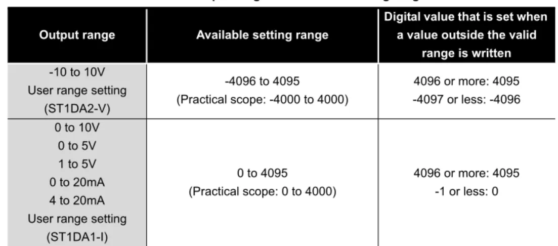
Analog output range Digital input value Maximum resolution
ST1DA2-V ST1DA2-V-F01
(Voltage)
0 to 10 V
0 to 4000
2.5 mV
0 to 5 V 1.25 mV
1 to 5 V 1.0 mV
-10 to 10V
-4000 to 4000 2.5 mV
User range setting 1.0 mV
ST1DA1-I ST1DA1-I-F01
(Current)
0 to 20 mA
0 to 4000
5 A
4 to 20 mA 4 A
User range setting 4 A
Br.n Wr.n
Bw.n Ww.n
Specific isolated area Isolation method Dielectric withstand Insulation resistance Between analog output
terminals and internal bus
Photo coupler insulation
560V AC rms/3 cycles (elevation
2000m)
500V DC 10M or more Between analog output
channels No insulation ---- ----
3 - 2
3.2 I/O Conversion Characteristics3 SPECIFICATIONS
* 1 When the hardware version is C or earlier, it is 100 to 500 .
3.2 I/O Conversion Characteristics
The I/O conversion characteristic indicates an inclination of a straight line that connects an offset value and a gain value at the time when the digital value written from the master station is converted into an analog value (voltage or current output).
The offset value is an analog value (voltage or current) output when the digital value is 0.
The gain value is an analog value (voltage or current) output when the digital value is 4000.
External AUX. power supply 24V DC (+20%/-15%, ripple ratio within 5%) 24V DC current: 0.065 A
5V DC internal current consumption 0.095 A
(0.10A is shown on the rating plate of the module.) External dimensions 77.6 (3.06 in.)(H) 12.6 (0.50 in.)(W) 55.4 (2.18 in.)(D) [mm]
Weight 0.04 kg
Table 3.1 Performance specifications list
Item Specification
3 SPECIFICATIONS
3.2 I/O Conversion Characteristics
3.2.1 Output characteristics of ST1DA2-V
3 - 3 1
OVERVIEW
2
SYSTEM CONFIGURATION
3
SPECIFICATIONS
4
SETUP AND PROCEDURES BEFORE OPERATION
5
GX Configurator-ST
6
PROGRAMMING
7
ONLINE MODULE CHANGE
8
COMMANDS
3.2.1 Output characteristics of ST1DA2-V
A graph of the ST1DA2-V output characteristic is shown below.
POINT
(1) Within the digital input and analog output scopes of each output range, the maximum resolution and accuracy are within the performance specification range. Outside those scopes, however, they may not fall within the
performance specification range. (Avoid using the dotted line part in Figure 3.1.)
(2) Set the offset/gain values for the user setting range *1 within a range in which the following conditions are satisfied.
(a) Offset/gain value setting range: -10 to 10V (b) (Gain value) (Offset value)
(c) { (Gain value) - (Offset value) } 4V
If condition (b) is not satisfied, ERR.LED turns on, the value will not be written to the module.
When the setting is outside the condition in (c), conversion is made but the resolution is within the maximum resolution range of the performance specifications.
Figure 3.1 Output characteristics of ST1DA2-V
Analog output voltage (V)
Digital input value
4095 4000 2000
-2000 -4000
-4096 -10
-5 0 5 10
Practical analog output scope
0 1
1), 2)
3) 4)
Number Analog Output Range Setting
Offset Value
Gain
Value Digital Input Value Maximum Resolution
1) -10 to +10V 0V 10V -4000 to 4000
2.5mV
2) 0 to 10V 0V 10V
0 to 4000
3) 0 to 5V 0V 5V 1.25mV
4) 1 to 5V 1V 5V 1.0mV
-- User range setting *1 *1 -4000 to 4000 1.0mV
3 - 4
3.2 I/O Conversion Characteristics 3.2.2 Output characteristics of ST1DA1-I3 SPECIFICATIONS
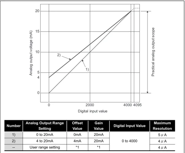
3.2.2 Output characteristics of ST1DA1-I
A graph of the ST1DA1-I output characteristic is shown below.
POINT
(1) Within the digital input and analog output scopes of each output range, the maximum resolution and accuracy are within the performance specification range. Outside those scopes, however, they may not fall within the
performance specification range. (Avoid using the dotted line part in Figure 3.2.)
(2) Set the offset/gain values for the user setting range *1 within a range in which the following conditions are satisfied.
(a) Offset/gain value setting range: 0 to 20mA (b) (Gain value) (Offset value)
(c) { (Gain value) - (Offset value) } 16mA
If condition (b) is not satisfied, ERR.LED turns on, the value will not be written to the module.
When the setting is outside the condition in (c), conversion is made but the resolution is within the maximum resolution range of the performance specifications.
Figure 3.2 Output characteristics of ST1DA1-I
Analog output voltage (mA)
Digital input value
4095 4000 0
0 5 10 15 20
Practical analog output scope
2000 4
2)
1)
Number Analog Output Range Setting
Offset Value
Gain
Value Digital Input Value Maximum Resolution
1) 0 to 20mA 0mA 20mA
0 to 4000
5 A
2) 4 to 20mA 4mA 20mA 4 A
-- User range setting *1 *1 4 A