1
Simulation and Experimental Studies on Double-fed Induction Generator Power Control at
Subsynchronous Operating Speed
Rog´ erio Vani Jacomini, Alex Pereira Fran¸ca and Edson Bim School of Electrical and Computer Engineering
State University of Campinas - UNICAMP Campinas, SP, Brazil
Email: [email protected], [email protected] and [email protected]
Abstract —Two control schemes for active and reac- tive power of a double-fed induction generator with the stator connected direct to the constant frequency, three phase grid are described. First the direct and quadrature rotor current components are generated based on the mathematical model of the machine. The second scheme used a PI controller to generate the rotor current reference components. The principles of both schemes are described in detail in this paper with a strong experimental approach. A complete simulation model is developed and several studies are performed to test its under different conditions. A laboratory test setup consisting of a wound rotor induction machine and driven by a variable speed squirrel cage induction motor is used to validate the control schemes proposed and the simulation results.
I. INTRODUCTION
Renewable energy including solar, wind, tidal, tidal cur- rent, small hydro, geothermal, refuse derived fuel, and fuel cell energies, is sustainable, reusable, and environmentally friendly clean energy. With the depletion of fossil fuels and the enforcement of stricter international environment regulations after the adoption of The Kyoto Protocol to the Convention on Climate Change, renewable energy has become very important energy source. [1]
Since the early of 1980s, the wind technology capital costs have droped by 80 percent and availability factors of grid-connected plants have risen to 95 percent. These factors have jointly contributed to the decline of the wind electricity cost by 70 percent to 5 to 7 cents per kWh.
The goal of ongoing research programs funded by the U.S. Department of Energy and the National Renewable Energy Laboratory is to bring the wind power cost highly competitive with the energy cost of conventional power technologies. For this reasons, wind power plants are now supplying economical clean power in many parts of the world.[2]
In recent years double-fed induction machines (DFIM) became very attractive to the variable speed wind power generating systems, because of its flexibility is effectively possible to improve the capturing wind energy capability [3]. The fundamental feature of double-fed induction ma- chine, including drive and generating systems, is that the
power processed by the power converter is only a small fraction of total system power [4], for this reason the rotor windings induction generator it is an available option for medium and high power applications.
Conventional design of DFIM control systems is based on rotor current vector control with d-q decoupling [5], [6].
The control system is usually defined in the synchronous d-q frame fixed to the stator flux, while Xu and Cheng [4] uses the orientation of air gap flux, requiring some simplification. Through the orientation of the stator flux, the power factor control is made by the independent control of active and reactive power [7], [8], [9], using a PI controller to set the rotor current reference values [10], [11]. At [12] is presented a control method that allows a wind turbine to operate with the optimum power efficiency over a wide range of wind speeds. In both papers presented above, the stator flux oriented was adopted. This approach have a wide range use because allows the independent control of active and reactive powers [13].
In this paper are presented two control methods to active and reactive power flow control for a double-fed in- duction generator connected direct to the three phase grid, operating at subsynchronous speed range. A based model control method and a PI control method. Both methods are widely tested including by a experimental point of view, and that performance are extensive evaluated.
II. MATHEMATIC MODEL AND CONTROL SYSTEM
The dynamic machine equations presented in the syn- chronous reference frame are [13]
( v ds = R s i ds − ω 1 λ qs + dt d λ ds v qs = R s i qs + ω 1 λ ds + dt d λ qs
(1)
( v dr = R r i dr − (ω 1 − ω r )λ qr + dt d λ dr
v qr = R r i qr + (ω 1 − ω r )λ dr + dt d λ qr
(2)
( λ ds = L s i ds + L m i dr
λ qs = L s i qs + L m i qr
(3) PEDS2009
1421
2
( λ dr = L r i dr + L m i ds
λ qr = L r i qr + L m i qs (4) In the reference frame attached to the stator flux at steady conditions. As given below:
λ dqs = λ ds and λ qs = 0 (5) substituting (5) in (1) and (3) we have
v ds = R s i ds v qs = R s i qs + ω 1 λ ds (6)
i ds = λ ds L s
− L m L s
i dr i qs = − L m L s
i qr (7) The active and reactive power are obtained by following equations:
P s = 3
2 (v ds i ds + v qs i qs ) (8) Q s = 3
2 (v qs i ds − v ds i qs ) (9) Substituting (6) in (8) and (9), we have:
P s = 3
2 [ω 1 λ ds i qs + R s (i 2 ds + i 2 qs )] (10) and
Q s = 3
2 ω 1 λ ds i ds (11) Combining the equations (7), (10) and (11) the active and reactive power is given by:
Q s = 3 2
L m
L s ω 1 λ ds
h λ ds
L m − i dr
i
(12)
P s = − 3 2
L m
L s
ω 1 λ ds i qr + 3
2 R s (i 2 ds + i 2 qs ) (13) Considering λ ds constant, the reactive power is a func- tion only of i dr ; as regards the active power, the presence of current i ds in expression (13) characterizes a coupling between the active power and the current responsible for control of Q s , as can be seen at the equation (7).
Due the R s to be very small its proximately 0.01 pu to machine of hundreds kW and 0.06 pu to machine of smallers power values [14] this coupling results weak. If R s is ignored, what is perfectly acceptable to high power electrical machines, the final expression of stator active power is given by
P s = − 3 2
L m
L s ω 1 λ ds i qr (14) and the stator voltage components is given by
v ds = 0 e v qs = V ∞ = ω 1 λ ds (15) From the last equation, the direct axis stator flux is determined by the triphasic grid frequency and voltage;
what being constant, that particularly facilitates the un- derstanding of the machine operation.
A. Control system
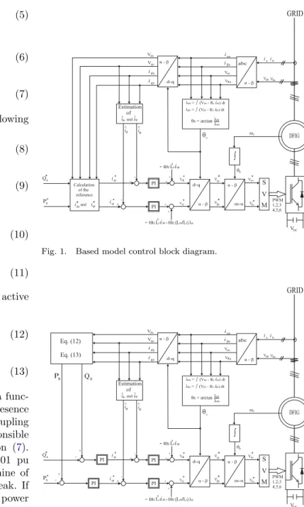
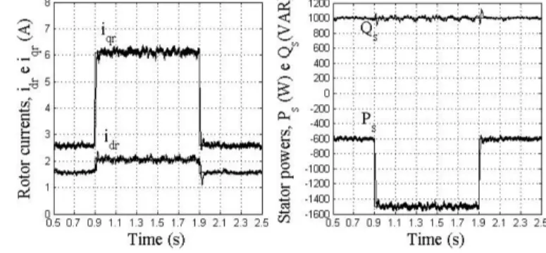
Fig. 1 shows the Based Model control block diagram, and Fig. 2 shows the PI controller diagram, both DFIG power control schemes are implemented at software simu- lation and experimental test bench also.
PI Estimation
of
ò
+
- +
+
+ -
DFIG
GRID
PI
abc
idrandqr
Q*s
Ps*
idr* iqr*
idr
iqr
^
^
^ ^
ids
iqs Vqs
iαs
iβs Vds
Vαs Vβs
Vαr
Vβr Vmr
Vnr Vdr
Vqr
*
*
*
*
*
*
iaib
VabVbc α - β
ωr
θr
θs
S V M
VDC +
+
- ω2Lriqr
- ω2Lridr +ω2(L L λm/r)s d-q α - β
i
d-q
α - β m-n
α - β λ =αs ∫(Vαs-Rs αsi) dt λ =βs ∫(Vβs-Rsiβs) dt θ = arcts anλαs
λβs
PWM 1,2,3 4,5,6 Calculation
of the reference i*drand iqr*
Fig. 1. Based model control block diagram.
PI Estimation
of
ò
+
- +
+
+ -
DFIG
GRID
PI
abc
idrandqr
Q*s
Ps*
idr*
iqr* idr
iqr
^
^
^ ^
ids
iqs Vqs
iαs
iβs Vds
Vαs Vβs
Vαr
Vβr Vmr
Vnr Vdr
Vqr
*
*
*
*
*
*
iaib
VabVbc α - β
ωr
θr
θs
S V M
VDC +
+
- ω2Lriqr
- ω2Lridr +ω2(L L λm/r)s d-q α - β
i
d-q
α - β m-n
α - β λ =αs ∫(Vαs-Rs αsi) dt λ =βs ∫(Vβs-Rsiβs) dt
θ = arcts an λαs λβs
PWM 1,2,3 4,5,6 PI
PI
Qs Ps
-
- +
+
Eq. (12) Eq. (13)
Fig. 2. PI controller block diagram.
The i ∗ dr and i ∗ qr currents values are obtained by rewriting the Eqs. (8) and (9) such that the components of the stator current is depending the potential of stator, ie:
i ds = 1 v qs
(v ds i qs + 2
3 Q s ) (16)
and
i qs = 1 v qs
(−v ds i ds + 2
3 P s ) (17)
PEDS2009
1422
3
Substituting the Eqs. (16) and (17) in (7), we have
i ∗ dr = λ ds
L m
− L s
L m v qs
(v ds i qs + 2
3 Q ∗ s ) (18)
and
i ∗ qr = − L s L m v qs
(−v ds i ds + 2
3 P s ∗ ) (19) If R s = 0, we have that v ds =0 and v qs =∞, and rewriting as the Eqs. (18) e (19) are obtained
i ∗ dr = λ ds L m
− 2 3
L s L m ω 1 λ ds
Q ∗ s (20)
i ∗ qr = − 2 3
L s L m ω 1 λ ds
P s ∗ (21)
The PI controller generates the components i ∗ dr and i ∗ qr from the errors found in the stator active and reactive powers. The rotor currents i dr and i qr are estimated by the Eq. (7).
Two strategies for control of stator active and reactive power are implemented. In the first one the control scheme are based on Double-Fed Induction Generator (DFIG) model considering R s ; in second one ,PI controllers replace the machine model to generate the references i dr and i qr . For each one these strategies the DIFG operating at steady state with Q s =1 kVAR and P s =0,6 kW, undergoes a step active power ∆P s =-0.9 kW, it seems in all tests, where there is no control over mechanic energy primary source speed.
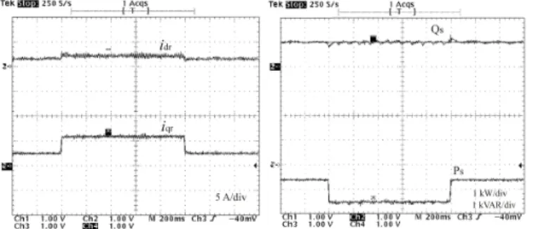
III. SIMULATED RESULTS
In the Fig. 3 are shown the power and current results for two control strategies. The control scheme based on DFIG model works very well at steady state, because the current reference components i ∗ dr and i ∗ qr are correct determined. By applying a step signal at P s , there is a substantial increase at i ∗ dr , and this fact on due the increase of stator flux, owing R s be weight in the model.
So, the control effort determines i ∗ dr correctly in order to be maintained Q s as a constant. The results achieved with PI controllers are showed at Fig.3(b). Once that power signals are not influenced by the value of R s . In the slip errors determination the PI controllers using the power values estimated by Eqs. (8) and (9). As the PI controllers requires the reference components of the rotor current, regardless if the model or there is no variation on stator flux or power loss the reference values are treated with zero error in steady state.
(a) Control based on DFIG model considering R
s.
(b) Control using PI controller.
Fig. 3. Test profile of Ps in the step of -600 W to -1.5 kW, with Qs
= 1 kvar.
IV. EXPERIMENTAL RESULTS
The proposed control strategy was implemented in a platform based on DSP TMS320F2812. The sampling frequency of currents and voltages was 20 kHz and the driver chopper frequency was 7.5 kHz.
Fig. 4. Laboratory test setup.
The experimental tests at Fig.5 agree with that were obtained based on simulation shown at Fig. 3. Indeed the dynamic response of active power obtained experimentally
PEDS2009
1423
4