碩士論文
Graduate Institute of Electronics Engineering College of Electrical Engineering and Computer Science
National Taiwan University Master Thesis
為達擺置線長最佳化考慮障礙區塊之端點傳遞
Blockage-Aware Terminal Propagation for Placement Wirelength Minimization
楊勝為 Sheng-Wei Yang
指導教授:張耀文 博士 Advisor: Yao-Wen Chang, Ph.D.
中華民國 105 年 6 月
I would like to show my gratitude to my advisor, Professor Yao-Wen Chang.
Throughout my stay under Professor Chang, I have always felt honored to be his advisee. I appreciate every training I received from Professor Chang. I want to thank Doctor Tung-Chieh Chen for his tremendous guidance and insightful comments.
His distinguished expertise played a colossal role in my research and I have always learned from him in awe. Besides, I would like thank the committee members of my oral defense, Professor Hung-Ming Chen, Professor Ting-Chi Wang, and Professor Shao-Yun Fang for their valuable comments and suggestions.
I am thankful to every member of the Electronic Design Automation Labora- tory. Every experience I received here reflected in my life and polished my attitude towards life. I appreciate every inspiring discussions and useful comments from my lab members. Especially, I would like to thank Chau-Chin Huang, who helped me enormously with my research. I am grateful to do the project with Szu-To Chen and Chin-Hao Chang, who have been great partners in collaboration.
My deepest gratitude goes to my family. They have been supporting me throughout my pursuit of academic achievements. Without their eternal love and constant supports, this thesis would never be completed.
Sheng-Wei Yang National Taiwan University
June 2016
研究生:楊勝為 指導教授:張耀文 博士
國立臺灣大學電子工程學研究所 摘要
在電路擺置演算法的發展中,線長最佳化一直是電路擺置問題最重 要的其中一個目標。隨著製程的演進,縱使擺置問題出現了許多新目 標與限制條件,繞線線長始終是現代電路擺置器中一個無法忽視的最 佳化目標。電路擺置器多年來往往使用連線半周長作為衡量線長的比 較標準。但連線半周長只有計算連線定界框周長的一半,因而過度簡 化了連線線長。雖然連線半周長是一個快速又有效率的連線估計方法,
它卻無法反映一個連線是否可能產生迂迴繞線的情形。這是因為連線 半周長計算連線長度時忽略了連線內部的連接狀態、連接數量以及是 否繞過障礙區塊。在有障礙區塊的設計電路中,即使周遭仍有足夠區 域的可擺置空間,以連線半周長為最佳化目標的電路擺置器很可能會 為了達到連線半周長最佳化而將可移動之元件擺置在障礙區塊之上。
這種現象很容易在障礙區塊附近形成迂迴繞線。另一方面,現今有很
因此,重新修正這些高效能電路擺置器的引擎會非常困難與昂貴。於 是,我們需要一個有效可以解決這個因為連線半周長而導致迂迴繞線 的演算法,但又不能改變原本電路擺置器以連線半周長為最佳化核心 目標的引擎。因此,這篇論文題出了一個端點傳遞電路擺置流程。端 點傳遞電路擺置流程把我們提出的端點傳遞演算法和傳統電路擺置流 程整合。端點傳遞的主要構想是依據每塊障礙區塊上的端點之連線情 形創造端點空間,並將端點空間傳遞至估計繞線連線長最佳化之位置。
在迂迴繞線情況嚴重時,把擺置問題轉換成最小成本最大流問題並使 用相對應的圖學演算法尋找最佳解。實驗數據顯示,相比於傳統電路 擺置流程,本論文題出的端點傳遞電路擺置流程可以在不同的設計電 路中皆達到更佳的全域繞線線長。
關鍵詞:實體設計、電路擺置、端點傳遞、線長最佳化
Student: Sheng-Wei Yang Advisor: Dr. Yao-Wen Chang
Graduate Institute of Electronics Engineering National Taiwan University
Abstract
Throughout the development of placement algorithms, wirelength minimiza- tion has been one of the most important objectives for all placement problems.
Although numerous objectives and constraints are added into placement problems, routed wirelength is still a non-negligible objective to almost all modern placement problems. Placers have been using half-perimeter wirelength (HPWL) as the metric for wirelength minimization for ages. However, HPWL oversimplifies wirelengths of nets by taking only the half-perimeter of the bounding boxes of nets. HPWL, although fast and efficient, cannot reflect possible routing detours due to its neglect of connectivities and blockages within bounding boxes of nets. For designs with preplaced blocks, placement algorithms with HPWL as their objective function can easily place cells onto preplaced blocks for the fullest minimization on half perime- ter wirelength, in lieu of placeable regions. Such phenomenon may easily lead to serious routing detours around preplaced blocks. On the other hand, many well- developed modern placers are based on HPWL minimization, which makes HPWL too expensive to be replaced by any modified cost metrics. Therefore, an effective
the original placement objective of HPWL minimization. This thesis describes an effective and efficient terminal propagated placement flow by integrating our fast and feasible preplacement algorithm into traditional placement flow. The main idea of our algorithm is to create an area for each preplaced terminal according to the connectivity of the terminal, and propagate preplaced terminals to feasible locations with minimized approximated routed wirelength from the original position to the propagated position. A mininum-cost maximum flow algorithm is applied if neces- sary to ensure that a propagation with optimal approximated routed wirelength is performed by our algorithm. Experimental results show that our flow outperforms traditional flow by 4% in average global routed wirelength.
Keywords: Physical Design, Placement, Terminal Propagation, Wirelength Mini- mization
Acknowledgements iii
Abstract (Chinese) iv
Abstract vi
List of Tables x
List of Figures xi
Chapter 1. Introduction 1
1.1 Wirelength Models for Placement . . . 1
1.2 Modern Placement Algorithms . . . 4
1.3 Related Works . . . 8
1.4 Our Contributions . . . 9
1.5 Thesis Organization . . . 10
Chapter 2. Preliminaries 12 2.1 Motivation . . . 12
2.2 Routing Resources . . . 15
2.3 Problem Formulation . . . 17
Chapter 3. Terminal Propagation Algorithm 18 3.1 Algorithm Overview . . . 18
3.2 Terminal Space Allocation . . . 21
3.3 Obstacle-Aware Propagation . . . 24
3.4 Optimal Routing Resource Distribution . . . 27
4.2 Experimental Results and Comparison . . . 33
Chapter 5. Conclusions and Future Work 46
Bibliography 50
4.1 #Blockages, #Modules, #Nets, #Pins denote the number of pre- placed blocks, movable cells, nets, terminals respectively . . . 34 4.2 #Blockages, #Modules, #Nets, #Pins denote the number of pre-
placed blocks, movable cells, nets, terminals respectively . . . 34 4.3 Resulting Global Routed Wirelength (GR-WL) between NTUplace4
and our placement flow for benchmarks from the champion of 2015 Routability-Driven Placement Contest . . . 35 4.4 Resulting Runtime (CPU) between NTUplace4 and our placement
flow for benchmarks from the champion of 2015 Routability-Driven Placement Contest. TP-CPU, Place-CPU, TOTAL-CPU stand for terminal propagation, NTUplacce4 and total runtime in Blockage Terminal Propagation Placement. . . 35 4.5 Resulting Global Routed Wirelength (GR-WL) between NTUplace4
and our placement flow for benchmarks adapted from ISPD’05 Contest 36 4.6 Resulting Runtime (CPU) between NTUplace4 and our placement
flow for benchmarks from ISPD’05 Contest. TP-CPU, Place-CPU, TOTAL-CPU stand for terminal propagation, NTUplacce4 and total runtime in Blockage Terminal Propagation Placement. . . 37
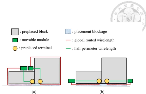
1.1 An illustration of blockage detour problem. (a) A placement result with minimized HPWL. Despite that HPWL of this placement result is nearly optimal, the resultant global routed wirelength is signifi- cantly larger than its HPWL. (b) A placement result with minimized global routed wirelength. Although HPWL of this placement result is significantly larger than that of (a), global routed wirelength is much shorter, and difference between HPWL and global routed wirelength is much smaller than that of (a). . . 4 1.2 A typical placement result of a design with preplaced blocks. The
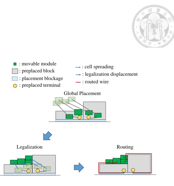
green rectangles represent movable cells. The grey rectangles rep- resent preplaced blocks. The yellow circles represent terminals of preplaced blocks. The blue-slashed rectangles represent placement blockages. The grey arrows represent cell spreading directions. The blue arrows represent legalization displacement. The red line seg- ments represent global routed wire. A typical placer with HPWL as wirelength minimization metric can easily place cells onto preplaced blocks to shorten the distance between movable cells and preplaced terminals. In legalization stage, the movable cells on preplaced blocks are moved to the nearest legal positions. The global routed wirelength of the nets connecting preplaced terminals is significantly larger than its HPWL. . . 7 1.3 An illustration for our work. The region below the preplaced blocks
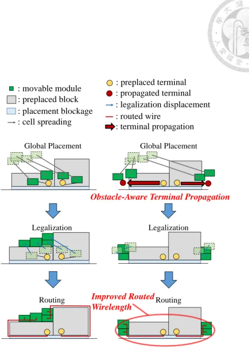
is not placeable. (a) Result of traditional placement flow. The tradi- tional placement result falls short of routed wirelength of preplaced blocks terminals. (b) Result of terminal propagated placement flow.
The revised flow fuse traditional placement flow with terminal prop- agation algorithms. Thus, a detour-minimized solution is obtained while the well-developed HPWL minimization algorithms can still be utilized. . . 11
also inhibits modules from passing through blockages. The grey rect- angles represent blockages with normal costs. The red rectangles represent blockages with raised costs. The green rectangles represent movable cells. The yellow circles represent terminals of preplaced blocks. The arrows represent placement cell spreading. (a) Mov- able cells can be spread through blockages in order for placement algorithms to find preferred placement results with minimized wire- length. (b) If the costs of blockages are raised, the movable cells cannot be spread effectively, thus qualities of placement results are compromised. . . 14 2.2 With given routing architecture, we can allocate the routing resources
of each routing tile according to net connections. (a) A routed wire crossing through a G-cell t1vertically occupies a portion of its vertical routing resources. The vertical routing resources between t1 and t1u
as well as the resources between t1 and t1d are occupied by this wire.
(b) A routed wire crossing a G-cell t2 horizontally occupies a portion of its horizontal routing resources. The horizontal routing resources between t2 and t2l as well as t2 and t2r are occupied by this wire. (c) A routed wire crossing a G-cell t3 from t3r to t3u. This wire occupies the horizontal routing resources between t3 and t3r as well as vertical routing resources between t3 and t3u. . . 16 2.3 Notations in this thesis. . . 17 3.1 A comparison between the traditional placement flow and our ter-
minal propagation placement flow. (a) Traditional placement flow produces results with minimized HPWL, which may incur routing detours around preplaced blocks. (b) Our blockage terminal propa- gation placement flow handles blockage terminals prior to placement algorithm, which solves detours and without compromising the qual- ity of HPWL minimization algorithms. . . 19
nal. Then, an obstacle-aware propagation algorithm is performed to propagate terminals of preplaced blocks. Next, the routing re- sources are optimally redistributed if the approximated detours are still large after previous stages. Finally, the placement algorithm optimize the placement according to the propagated terminals to ob- tained a detour-minimized placement result. . . 20 3.3 Each propagated terminal creates a square with an area that can
contain all the modules that were to be placed onto the preplaced blocks in global placement. . . 23 3.4 Unblocked regions are divided into propagation tiles, and the priority
for propagation is ranked by approximated routed wirelength. . . 26 3.5 Each routing tile is formulated as a vertex, and the capacity of each
edge represent the available routing resources between two routing tiles. 28 3.6 The formulation of routing resources is illustrated here. (a) Apply
routing tiles on preplaced blocks. (b) Resultant flow network for the formulated minimum-cost maximum flow problem. . . 29 4.1 The placement result of adaptec1Eval from (a) NTUplace4 without
terminal propagation and (b) NTUplace4 with our terminal propaga- tion algorithm. . . 38 4.2 The placement result of adaptec2Eval from (a) NTUplace4 without
terminal propagation and (b) NTUplace4 with our terminal propaga- tion algorithm. . . 39 4.3 The placement result of adaptec3Eval from (a) NTUplace4 without
terminal propagation and (b) NTUplace4 with our terminal propaga- tion algorithm. . . 40 4.4 The placement result of adaptec4Eval from (a) NTUplace4 without
terminal propagation and (b) NTUplace4 with our terminal propaga- tion algorithm. . . 41 4.5 The placement result of adaptec1 from (a) NTUplace4 without ter-
minal propagation and (b) NTUplace4 with our terminal propagation algorithm. . . 42
algorithm. . . 43 4.7 The placement result of adaptec3 from (a) NTUplace4 without ter-
minal propagation and (b) NTUplace4 with our terminal propagation algorithm. . . 44 4.8 The placement result of adaptec4 from (a) NTUplace4 without ter-
minal propagation and (b) NTUplace4 with our terminal propagation algorithm. . . 45 5.1 (a) Placement results without propagating terminals of movable macros
may have routing detours. (b) Consider terminal propagation for pins of movable macros. Routing detours are minimized and global routed wirelength is improved . . . 49
Introduction
In this thesis, we propose a terminal propagation algorithm to guide placement algorithms in solving placement problems to achieve minimized detours in global routed wirelength. In the following sections, we first briefly introduce some popular wirelength models for placement problems in Section 1.1 and modern placement algorithms in Section 1.2. Then, a survey of related works is given in Section 1.3.
Afterwards, we summarize our contributions in Section 1.4. Finally, in Section 1.5, we show the organization of the rest of this thesis.
1.1 Wirelength Models for Placement
A placement problem is defined as assigning movable modules to positions on the chip such that no two cells overlap with each other and some cost function is optimized [9]. Ideally, placement and routing should be performed simultane- ously. However, as the design complexity rises, it has become extremely hard to handle these two problems at the same time. Therefore, wirelength minimization has been the core optimization metric for placement algorithms. With the advance in placement algorithm developments, the objectives of placement algorithms may vary greatly. However, the most fundamental and important issue is still wirelength minimization. In order to achieve minimized wirelength, a number of wirelength
models are proposed for placers to evaluate the wirelengths of their placement re- sults. Among all models, four most popular examples of wirelength models are briefly introduced as below:
One of the simplest wirelength evaluation metric is half-perimeter wirelength, usually abbreviated as HPWL. HPWL of a net is derived by adding half the perime- ter of the bounding rectangle that encloses all pins of the net to be connected. HPWL is easy to compute, which makes it very popular among most modern placer. Let there be a net with N terminals. Let xi and yi denotes the x and y axis coordinates of terminal i respectively. Equation 1.1 shows the HPWL such net.
1≤i≤N,1≤j≤Nmax |xi− xj| + max
1≤i≤N,1≤j≤N|yi− yj|
(1.1) Beside HPWL, squared Euclidean distance of a net is calculated by squaring all pairwise pin distances in the net. Squared Euclidean distance has larger com- putational complexity than HPWL. Precisely, a net with n pins takes O(n2) time complexity to compute its squared Euclidean distance, but it takes only O(n) to find its HPWL. Even so, squared Euclidean distance is still considered as a relatively fast wirelength approximation technique, compared with more complex estimation methods described in latter passage. Let there be a net with N terminals. Let xi and yi denotes the x and y axis coordinates of terminal i respectively. Let γij be the net weight coefficient from terminal i to j. Equation 1.2 shows the squared Euclidean distance of the net.
1 2
N
P
i=1 N
P
j=1
γij[(xi − xj)2+ (yi− yj)2]
(1.2)
Notice that each two terminals are calculated twice, from terminal i to j
and from terminal j to i. Normally, γij should be the same as γji. To estimate wirelength from twice-calculated result, the constant 12 divides the result by two to derive an approximated wirelength.
Steiner-tree approximation of a net is computed by finding the total wire- length of the constructed minimum Steiner tree of the net. It is considered as one of the most accurate wirelength approximation model, but it is also one of the most computationally expensive one. Given that design complexity rises rapidly in mod- ern designs, it is impractical to approximate Steiner trees of all nets during each placement iteration.
Minimum spanning tree of a net is estimated by summing up the total wire- length of the minimum spanning tree of the net. Minimum spanning tree is an approximation to Steiner trees, which makes it more accurate than HPWL and squared Euclidean distance. However, minimum spanning tree is also more com- putationally expensive than squared Euclidean distance, and less accurate than Steiner-tree approximation.
Among all kinds of wirelength approximation models, half-perimeter wire- length has been the most commonly used wirelength approximation metric. The reason for its wide-spread popularity is attributed to its simplicity in calculation.
An HPWL of any net can be calculated in constant time if the bounding box of the net is already derived. In most placement algorithms, HPWL is considered as the main approximation cost metric for wirelength estimation.
: global routed wirelength : half perimeter wirelength
(a) (b)
: preplaced terminal : movable module
: placement blockage : preplaced block
Figure 1.1: An illustration of blockage detour problem. (a) A placement result with minimized HPWL. Despite that HPWL of this placement result is nearly optimal, the resultant global routed wirelength is significantly larger than its HPWL. (b) A placement result with minimized global routed wirelength. Although HPWL of this placement result is significantly larger than that of (a), global routed wirelength is much shorter, and difference between HPWL and global routed wirelength is much smaller than that of (a).
1.2 Modern Placement Algorithms
With the advance in technology nodes, modern placement problems include various objectives. It can be noticed recently in the variety of objectives in placement contests. For instance, routability-driven placement contests focus on minimizing routing congestions [1] [3] [4]. Timing-driven placement contest, on the other hand, centers in the resultant performance of early and late slacks for each gate [2]. De- spite the variety of objectives in modern placement problems, almost all placement contests construe wirelength minimization as one of their fundamental cost metric.
Therefore, modern placement algorithms are developed to optimize particular design objectives (routability, timing, power, etc) and minimize wirelength while simulta-
neously satisfies given technology constraints (non-overlapping, minimum width, etc).
Modern placers rely on approximated HPWL functions to derive placement solutions with minimized wirelength. State-of-the-art placers are developed with analytical algorithms, which can be classified into two categories by their objec- tive functions. Quadratic placers [21] [22] [24] minimize the total squared distance between every pair of pins in every net while nonlinear placers (non-quadratic plac- ers) [10] [11] [15] [16] [17] [18] [19] optimize constrained minimization problems with approximated HPWL objectives. Approximation functions of HPWL used in nonlinear placers are designed to be smooth and differentiable. Therefore, many well-developed differentiable HPWL models were designed to be used in analytical placers [14] [26].
Nevertheless, when it comes to preplaced blocks, which are very common in modern placement problems, placers are unable to detect if a net would detour from preplaced blocks judging from its HPWL. Sometimes a routing detour from a preplaced block is so large that the routed wirelength of the net can be multiple times larger than its HPWL. Thus, placement results with minimum HPWL cannot guarantee absolute superiorities in routed wirelength.
Modern placers often divide placement problems into three stages: (1) global placement, (2) legalization, and (3) detailed placement. However, this divide-and- conquer manner may lead to a more serious mismatch between HPWL and routed wirelength. Figure 1.2 illustrates a typical three-stage placement flow. For de- signs with preplaced blocks, global placement can generate results with minimized HPWL, but it can easily place cells on preplaced blocks for the fullest optimiza- tion of its objective function. At the legalization stage, state-of-the-art legalizers focus on displacement minimization and possible HPWL minimization, which find
the nearest legal solutions for cells placed on preplaced blocks. Finally, detailed placement incrementally improve placement quality by reallocating movable cells while preserving legality. Not only for three-staged placers, nearly all placers with HPWL as wirelength minimization objective can easily result in large detours from preplaced block pins to cells if routability of preplaced blocks terminals are not handled. Thus, placers without considering preplaced blocks terminals can result in inferior routed wirelength in contrast to their superiorities in HPWL.
Figure 1.1 shows a simple example of routing detour problem from preplaced blocks. The grey rectangles represent preplaced blocks. The green rectangles repre- sent movable modules. The blue-slashed rectangles represent placement blockages.
The yellow circle represent preplaced terminals. The red lines represent routed wires.
The green lines represent half perimeter wirelengths. In Figure 1.1 (a), the mov- able cells, painted in green, are placed at positions with minimized HPWL. Despite that HPWL of this placement result is nearly optimal, the resultant global routed wirelength is significantly larger than its HPWL. In Figure 1.1 (b), although HPWL of this placement result is significantly larger than that of (a), global routed wire- length is much shorter, and difference between HPWL and global routed wirelength is much smaller than that of (a).
Global Placement
Legalization Routing
: movable module : preplaced block : preplaced terminal
: legalization displacement : routed wire
: cell spreading : placement blockage
Figure 1.2: A typical placement result of a design with preplaced blocks. The green rectangles represent movable cells. The grey rectangles represent preplaced blocks. The yellow circles represent terminals of preplaced blocks. The blue-slashed rectangles represent placement blockages. The grey arrows represent cell spread- ing directions. The blue arrows represent legalization displacement. The red line segments represent global routed wire. A typical placer with HPWL as wirelength minimization metric can easily place cells onto preplaced blocks to shorten the dis- tance between movable cells and preplaced terminals. In legalization stage, the movable cells on preplaced blocks are moved to the nearest legal positions. The global routed wirelength of the nets connecting preplaced terminals is significantly larger than its HPWL.
1.3 Related Works
The keyword “terminal propagation” in physical design was first mentioned in a paper about min-cut placement algorithm [13]. Min-cut placement algorithms apply a propagation algorithm to consider external terminal connections during local partitioning. Such technique was adopted in many min-cut placers [7] [8] [20] [27] [28].
Previously, there are some works that addressed issues with preplaced blocks.
The first analytical placer that handles preplaced blocks uses base potential smooth- ing technique [11]. Various smoothing models were implemented and compared in [11] and they concluded that Gaussian smoothing with level smoothing gives best smoothing result. Without proper smoothing technique, movable modules are likely to be trapped between preplaced blocks, which prevents placement al- gorithms from performing effective cell spreading. By implementing the smoothing technique, movable cells are able to spread through preplaced blocks. In 2015, Bustany et al. held ISPD Blockage-Aware Detailed Routing-Driven Placement Con- stest [4]. The top two teams handle detailed routability throughout every stage of their placers [18] [12]. However, all of the above works and modern placers adopt HPWL as wirelength metric, which makes this HPWL-rooted problem indistinguish- able from modern placers. HPWL has been the most widely accepted wirelength metric in placement algorithms. Given all those well-formulated HPWL approxi- mation models and well-developed placement engines, extinguishing such routing detours is very hard, and it is too expensive to develop new wirelength approxima- tion metric to replace HPWL. Here comes the real question: is it possible to solve this HPWL-based routing detour problem without changing the existed placement objective?
1.4 Our Contributions
Can HPWL-based routing detour problems be solved without altering the ex- isted placement objective? The answer to the question is a definite yes. In this the- sis, we present a blockage-aware terminal propagation algorithm to effectively handle blockage-related routing detours. Figure 1.3(b) shows a placement flow with our ter- minal propagation algorithm applied. Our revised terminal propagation placement flow propagates the preplaced blocks terminals at the preplacement stage, which makes global placement spread cells to detour-minimized locations. The subsequent legalization benefits from minimized displacement and the legalized cells are placed at locations with minimized wirelength to the terminals. Therefore, the resultant routed wirelength is improved because routing detours are eliminated, which means the discrepancy between HPWL and global routed wirelength is minimized. To sum up, the contributions of this work are listed as below:
• Though HPWL-based routing detours have existed for a long time, this is the first work dedicated to tackle this issue. This thesis formulate this HPWL- based routing detour problem into a terminal propagation placement problem and propose an effective algorithm to solve it.
• Our algorithm guarantees to find a set of locations for propagated terminals with minimal approximated global routed wirelength between original termi- nals and propagated terminals, if there exists any. The optimality of our proposed algorithm is mathematically guaranteed by a proper formulation of terminal propagation problems to minimum cost maximum flow problems.
• Our algorithm handles terminals of preplaced blocks prior to placement, which makes our algorithm applicable for any kind of placers. Placers integrating our
algorithm can now solve placement problems with minimized routing detours from preplaced blocks.
• Though preplaced terminal routing detours are rooted from HPWL minimiza- tion, our proposed algorithm can solve this issue without changing HPWL minimization objective in placement algorithms.
1.5 Thesis Organization
The remainder of this thesis is organized as follows. Section 2 formulates the blockage terminal propagation problem. Section 3 details our algorithm. Section 4 shows the experimental results. Section 5 concludes this thesis.
: movable module : preplaced block
: preplaced terminal : legalization displacement : routed wire
: cell spreading : placement blockage
Global Placement
Legalization
Routing
(b) Global Placement
Legalization
Routing
(a)
: propagated terminal
: terminal propagation
Improved Routed Wirelength
Obstacle-Aware Terminal Propagation
Figure 1.3: An illustration for our work. The region below the preplaced blocks is not placeable. (a) Result of traditional placement flow. The traditional placement result falls short of routed wirelength of preplaced blocks terminals. (b) Result of terminal propagated placement flow. The revised flow fuse traditional placement flow with terminal propagation algorithms. Thus, a detour-minimized solution is obtained while the well-developed HPWL minimization algorithms can still be utilized.
Preliminaries
In this section, we give the motivation of this thesis first, and then we introduce the routing resources of a placement problem. Finally, we define blockage terminal propagation placement problem.
2.1 Motivation
As design complexity grows exponentially, detecting and solving nets with possible routing detours during the placement stage is considered intricate. For example, some placers adopt weighted Half-Perimeter WireLength (wHPWL) as their goal for wirelength minimization. Unlike HPWL, wHPWL calculates each net wirelength by the product of its HPWL and a weight. Intuitively, placers with wHPWL as objective function can assign nets crossing preplaced blocks with low weights to prevent cells from spreading onto the preplaced blocks. However, as the instance illustrated in Figure 1.2, the spreading directions of the green cells are still dominated by their HPWL functions regardless of their weights. In other words, no matter how low the weights are assigned to these green cells, their spreading directions will not change because their individual optimization objectives are still half-perimeter wirelength. Furthermore, lowering weights of certain nets inhibits them from spreading toward their target locations, which is basically undermining
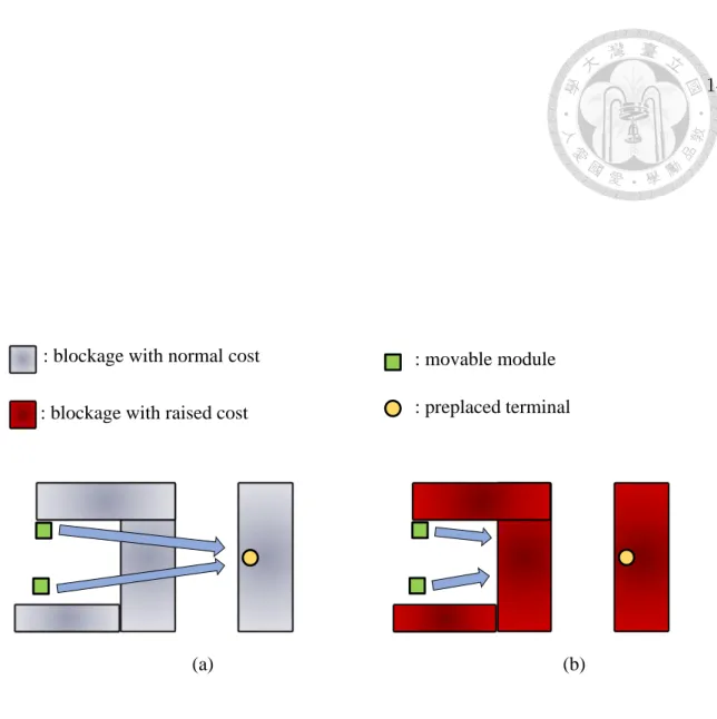
the objective of placement algorithm. Figure 2.1 shows the downside of lowering weights of nets crossing blockages. In Figure 2.1 (a), movable cells can be easily spread through preplaced blocks. Placement algorithms can find placement results with minimized wirelength in terms of HPWL between movable cells and preplaced terminals. In Figure 2.1 (b), the costs of nets crossing the blockages are raised.
This change compromises the spreading force on these movable cells. As a result, the movable cells are inhibited from spreading to desired locations with minimized wirelength, despite that the spreading directions for these movable cells might be very promising. Thus, minimizing weights of nets crossing preplaced blocks can hardly solve routing detours from preplaced blocks.
In a traditional placement flow, placement algorithms can easily place mov- able cells onto preplaced blocks to minimize HPWL of nets of preplaced terminals.
Despite that numerous techniques hinder cells from being placed onto preplaced blocks, a placement result produced by traditional placement flow has significantly larger routed wirelength than its HPWL. Therefore, we need an effective algorithm that can prevent placement algorithms from placing movable cells onto preplaced blocks. Adjusting the weight of nets crossing preplaced blocks is a way to make problems disappear. However, just because movable cells are not placed onto pre- placed blocks does not mean that these movable cells are placed to better locations.
The problem of cells being placed onto preplaced blocks is resulted from an improb- able minimization of HPWL of nets connecting terminals of preplaced blocks. To solve this problem without changing the HPWL minimization objective, the prob- lem should be focused on the terminals, instead of the nets connecting the terminals.
Thus, a terminal propagation algorithm is needed to be developed to find feasible optimization directions for cell spreadings.
Adding cost to blockage could prevent modules from spreading onto preplaced blocks, but such handling also inhibits modules from passing through blockage
: blockage with normal cost : blockage with raised cost
: movable module
(a) (b)
: preplaced terminal
Figure 2.1: Adding cost to blockages (nets crossing blockages) can possibly pre- vent modules from spreading onto preplaced blocks, but such handling also inhibits modules from passing through blockages. The grey rectangles represent blockages with normal costs. The red rectangles represent blockages with raised costs. The green rectangles represent movable cells. The yellow circles represent terminals of preplaced blocks. The arrows represent placement cell spreading. (a) Movable cells can be spread through blockages in order for placement algorithms to find preferred placement results with minimized wirelength. (b) If the costs of blockages are raised, the movable cells cannot be spread effectively, thus qualities of placement results are compromised.
2.2 Routing Resources
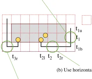
Global routing resources are available routing tracks that can be used to solve global routing problems. The objective of a global routing problem is to obtain minimized routed wirelength with a given placement result and global routing resources. To model global routing resources, grid graph models are often applied to formulate global routing problems. Figure 2.2 shows that the routing regions are divided into uniform and non-overlapping routing tiles called G-cells. The routing resources of a G-cell can be divided into four parts by their direction toward its adjacent G-cells. A routed wire crossing through a G-cell t1 vertically occupies a portion of its vertical routing resources. The vertical routing resources between t1 and t1u as well as the resources between t1 and t1d are occupied by this wire. A routed wire crossing a G-cell t2 horizontally occupies a portion of its horizontal routing resources. The horizontal routing resources between t2 and t2l as well as t2 and t2r are occupied by this wire. A routed wire crossing a G-cell t3 from t3r to t3u. This wire occupies the horizontal routing resources between t3 and t3r as well as vertical routing resources between t3 and t3u.
To solve blockage terminal propagation placement problems, we consider routing resources with G-cells in our algorithm. Our terminal propagation algo- rithm utilizes the information of G-cells to perform approximations on global routed wirelength and routability.
: G-cell
(b) Use horizontal routing resources (a) Use vertical routing resources
(c) Use horizontal and vertical routing resources
t
1t
1ut
1bt
2t
2rt
2lt
3t
3rt
3uFigure 2.2: With given routing architecture, we can allocate the routing resources of each routing tile according to net connections. (a) A routed wire crossing through a G-cell t1 vertically occupies a portion of its vertical routing resources. The vertical routing resources between t1 and t1u as well as the resources between t1 and t1d are occupied by this wire. (b) A routed wire crossing a G-cell t2 horizontally occupies a portion of its horizontal routing resources. The horizontal routing resources between t2 and t2l as well as t2 and t2r are occupied by this wire. (c) A routed wire crossing a G-cell t3 from t3r to t3u. This wire occupies the horizontal routing resources between t3 and t3r as well as vertical routing resources between t3 and t3u.
2.3 Problem Formulation
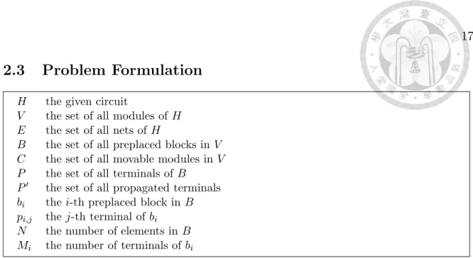
H the given circuit
V the set of all modules of H E the set of all nets of H
B the set of all preplaced blocks in V C the set of all movable modules in V P the set of all terminals of B
P0 the set of all propagated terminals bi the i-th preplaced block in B pi,j the j-th terminal of bi
N the number of elements in B Mi the number of terminals of bi
Figure 2.3: Notations in this thesis.
The blockage terminal propagation placement problem can be formulated as a graph minimization problem. Given a circuit represented as a hypergraph H = (V, E). Let vertices V = {B ∪ C} be all fixed and movable modules, where B = {b1, b2, b3, ..., bN} represents preplaced blocks and C represents movable cells.
Let E be the nets. Let the terminals of preplaced blocks be P = {p1,1, p1,2, ..., p1,M1, p2,1, ..., p2,M2, ..., pN,1, ..., pN,MN}, where pi,j represents the j-th terminal of preplaced block bi. Let xpi,j and ypi,j be the x and y coordinates of pi,j. The blockage terminal propagation placement problem is to find a set of propagated terminals P0 = {p01,1, p01,2, ..., p0N,M
N} such that by determining the desired position of C with respect to P0, the routed wirelength of the placement result is minimized while technology constraints are satisfied.
Terminal Propagation Algorithm
Figure 3.1 gives a simple comparison between a traditional placement flow and our proposed algorithm. Our proposed flow features a terminal propagation technique applied at the preplacement stage. By integrating our terminal propagation algo- rithm to a traditional placement algorithm, placement results with minimized global routed wirelength can be obtained without compromising the polished minimization mechanisms of the original placers. In this chapter, we would first show an overview of our algorithm, and then explain our terminal propagation algorithm step by step.
3.1 Algorithm Overview
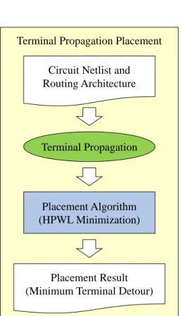
Figure 3.2 summarizes the overall flow of our proposed algorithm. The ter- minal space allocation algorithm is conducted for each terminal of preplaced blocks to ensure the propagated spaces have the capacity of containing all the cells that would spread toward them. A routed wirelength approximation is then applied to derive a cost for each possible propagation location. With the cost calculated, an obstacle-aware propagation algorithm is performed to find a propagation result with minimum cost. If the routing detours are still large, a min-cost maximum flow network algorithm is applied to ensure the optimality of the solution quality. The techniques of our algorithm are detailed in the following sections.
Traditional Placement
Placement Algorithm (HPWL Minimization)
(a)
Terminal Propagation Placement
Terminal Propagation
Placement Algorithm (HPWL Minimization)
(b) Circuit Netlist and
Routing Architecture
Circuit Netlist and Routing Architecture
Placement Result
(with terminal detours) Placement Result
(Minimum Terminal Detour)
Figure 3.1: A comparison between the traditional placement flow and our terminal propagation placement flow. (a) Traditional placement flow produces results with minimized HPWL, which may incur routing detours around preplaced blocks. (b) Our blockage terminal propagation placement flow handles blockage terminals prior to placement algorithm, which solves detours and without compromising the quality of HPWL minimization algorithms.
Terminal Space Allocation
Circuit Netlist Routing Architecture
Obstacle-Aware Propagation
Optimal Routing Resources Distribution Detour > threshold
Yes No
Placement Result
Figure 3.2: An overview of our terminal propagation placement flow. First, our algorithm creates a terminal space for each preplaced block terminal. Then, an obstacle-aware propagation algorithm is performed to propagate terminals of pre- placed blocks. Next, the routing resources are optimally redistributed if the approx- imated detours are still large after previous stages. Finally, the placement algorithm optimize the placement according to the propagated terminals to obtained a detour- minimized placement result.
3.2 Terminal Space Allocation
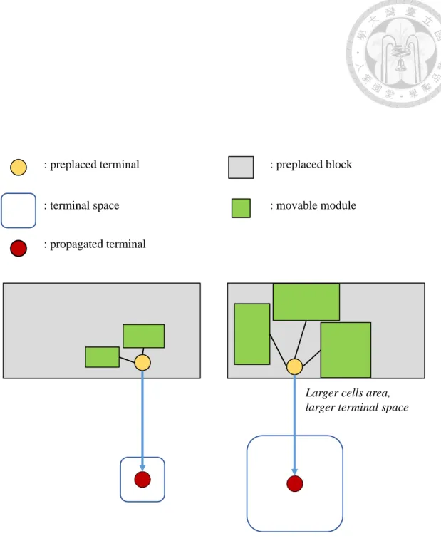
The first step of our algorithm is to define terminal spaces. In traditional placement flow, movable cells with nets connecting to preplaced terminals are prone to be spread onto preplaced blocks for minimized HPWL. Therefore, a propagation without considering the sizes of cells connected to terminals may possibly lead those cells to an region with insufficient free space. To properly handle the cells connecting to terminals of preplaced blocks, we introduce terminal spaces to represent the area of cells that were to be placed onto preplaced blocks. A terminal space of a terminal is a region with an estimated cell area. This terminal space has an area that is positively related the sum of areas of movable cells connected to this terminal.
These movable cells that were supposed to be placed onto preplaced blocks should be able to be contained in this terminal space. Figure 3.3 shows that two terminals with different cell areas result in different sizes of terminal spaces. In Figure 3.3 (a), there are only two movable modules connecting to the preplaced terminal, and the total area of the two movable modules is not very large. Therefore, the area of the terminal space is relatively small. In Figure 3.3 (b), there are three movable modules being placed onto the preplaced block to minimize the HPWL between the movable modules and the preplaced terminal. Furthermore, these three movable modules all have an area larger than any of the movable cell in Figure 3.3. Thus, to consider minimizing possible overlaps between movable modules connecting to preplaced blocks, the terminal space in Figure 3.3 (b) should be larger than that in Figure 3.3 (a).
Because terminal propagation is performed prior to placement stages, an algorithm predicting whether a cell would be spread onto preplaced blocks should be effectively applied. We propose Algorithm 1 to predict the size of a terminal space.
Algorithm 1 Terminal Space Allocation
Input: pi,j: the j-th terminal of preplaced block i Output: Spi,j: the terminal space of pi,j
1: Define scalable parameters λ+> 1, 0 < λ− < 1
2: A(Spi,j) = 0
3: for each cell ck ∈ Γ(pi,j)
4: λ ← 1
5: for each net nu of ck
6: if nu connects to bi
7: λ ← λλ+
8: if nu connects to bt, t 6= i
9: λ ← λλ−
10: A(Spi,j) ← A(Spi,j) + λA(ck)
Given a preplaced terminal pi,j, we define Spi,j as the terminal space of the propagated terminal p0i,j. Let Γ(pi,j) represent the set with all cells connecting to pi,j. Let the area of Spi,j and Γ(pi,j) be A(Spi,j) and A(Γ(pi,j)), respectively.
Theorem 1 Let there be |CP| cells connected to a preplaced terminal, and totally
|CC| cells connected to the |CP| cells. The time complexity of terminal space alloca- tion is O(|CP||CC|).
Proof 1 For a cell connected to a preplaced terminal, the time complexity of finding all cells connecting to it is O(|CC|). Because every cell connecting to a preplaced terminal is queried, the worst case scenario for time complexity happens when all
|CP| cells connect to all |CC| cells, which means it needs |CP||CC| queries. There- fore, the time complexity of determining the terminal space of a preplaced terminal is O(|CP||CC|)).
(a) (b)
Larger cells area, larger terminal space
: terminal space : movable module
: preplaced block : preplaced terminal
: propagated terminal
Figure 3.3: Each propagated terminal creates a square with an area that can contain all the modules that were to be placed onto the preplaced blocks in global placement.
3.3 Obstacle-Aware Propagation
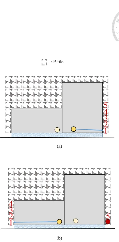
In a placement problem, a placeable region is defined as a region where movable modules can be placed in. In this stage of our algorithm, placeable regions are divided into propagation tiles (p-tiles), as illustrated in Figure 3.4. The width and height of p-tiles are scalable to placement problem size. Given a preplaced block terminal pi,j, a cost is given to each p-tile adjacent to the preplaced block bi. We define the cost of a p-tile for pi,j to be the estimated routed wirelength from pi,j to the p-tile.
To estimate a routing result from a terminal to a p-tile, a routing approxima- tion algorithm adopted from Lin et al. [23] is applied to evaluate possible detours.
For unblocked nets, our routing algorithm estimates the cost by directly calculat- ing the Manhattan distance between the terminal and the p-tile. For nets crossing routing blockages, an obstacle-avoiding spanning tree is constructed by connecting terminals to every corner of the blockages. All edges of the spanning tree is then in- dividually reconstructed to a Steiner tree. The result is found by selecting a feasible connection of Steiner trees with minimum routed wirelength.
With the cost of each p-tile calculated, we can formulate terminal propagation problem into a cost minimization problem. Let ˆW (pi,j, p0i,j) be the approximated routed wirelength connecting pi,j and p0i,j. Let Ov(Spi,j, Spk,l) stands for the set of elements between in Spi,j and Spk,l that have overlaps. Let Ov(Spi,j, B) stands for the set of elements between Spi,j and B which have overlaps. The objective of a terminal propagation problem is defined as Equation 3.1:
Algorithm 2 Obstacle-Aware Propagation
Input: pi,j: the j-th terminal of preplaced block bi Output: p0i,j: the propagated terminal of pi,j
1: cmin = LARGE N U M
2: t0 = N U LL
3: for each p-tile t adjacent to bi
4: if free space of t > Spi,j
5: ct= Calculate Obstacle Aware Cost(t)
6: if cmin > ct
7: cmin = ct
8: t0 = t
9: propagate p0i,j to t0
min
N
P
i Mi
P
j
W (pˆ i,j, p0i,j)
s.t. Ov(Spi,j, B) = φ,
Ov(Spi,j, Spk,l) = φ, ∀k 6= i ∨ ∀l 6= j
(3.1)
Theorem 2 Given a preplaced terminal, |T | p-tiles and N preplaced blocks. The time complexity of our obstacle-aware propagation algorithm is O(|T |N lgN )
Proof 2 Because our routing approximation only calculates nets between propagated terminals and the original terminals, the worst case scenario of our obstacle-aware propagation algorithm happens when all |T | p-tiles are calculated with 4N corners.
Calculate each p-tile takes O(N lgN ). Thus, the time complexity of calculating all p-tiles is O(|T |N lgN ).
1 2 3 4
5
(a)
(b)
1 2 3 4 5
: P-tile
Figure 3.4: Unblocked regions are divided into propagation tiles, and the priority for propagation is ranked by approximated routed wirelength.
Our obstacle-aware propagation algorithm can solve terminal propagation problems with minimized approximated wirelength. The propagation algorithm is fast and effective. It can find detour-free solutions if routing resources and placeable regions are not too scarce. However, for problems with scanty routing resources, the solution quality of obstacle-aware propagation is subject to the precedence of terminals. To solve this, an optimally routing resources distribution algorithm is described in the following subsection.
3.4 Optimal Routing Resource Distribution
For cases with scarce routing resources, obstacle-aware propagation can only guarantee the propagated terminals with minimum cost p-tile would result in the shortest routed wirelength. Therefore, we propose a routing resource distribution algorithm by formulating terminal propagation problems into escape routing prob- lems.
To model a terminal propagation problem into a graph, each routing tile is transformed into a routing tile node. Figure 3.5 shows how a set of given routing resources is formulated into a graph. Each routing tile node has an edge connected to adjacent routing tile node horizontally or vertically. The edge capacity represents the horizontal or vertical routing resources according to the type of the edge. For any net routed through a tile, it takes up a portion of the routing resources of the tile. When the horizontal (vertical) routing resources of a routing tile is depleted, no more nets can be horizontally (vertically) routed through it.
The transformed problem can be directly mapped to a minimum-cost maxi- mum flow problem (MCMF) mentioned in [6]. Our algorithm adopts the successive shortest path algorithm to find the minimum approximated routed wirelength with
: routing tile node
Ch : horizontal routing capacity Cv : vertical routing capacity 1/Cv
1/Ch 1/Cv
1/Ch 0/Ch
0/Cv 0/Ch
0/Cv
0/Cv 0/Ch
0/Ch 0/Cv
Figure 3.5: Each routing tile is formulated as a vertex, and the capacity of each edge represent the available routing resources between two routing tiles.
the maximum number of propagated terminals.
Based on the optimal routing resource distribution algorithm, we can derive the following theorem:
Theorem 3 Given |P | preplaced terminals and |G| G-cells, the time complexity of our optimal routing resource distribution algorithm is O(|G|2|P |).
Proof 3 Optimal routing resources distribution algorithm uses successive shortest path algorithm to solve minimum cost maximum flow problem. Successive short- est path algorithm finds optimal solution by iteratively search all O(|P |) augmented paths. Each path takes O(|G|2) time complexity. Thus, the time complexity of opti- mal routing resources distribution algorithm is O(|G|2|P |).
(a)
(b) 1/1
1/1
1/1 1/1
1/1
1/1
1/Ch0,0,1 1/Cv0,0,1
1/Cv4,1,2
1/Ch0,4,5 1/Ch0,5,6 1/Cv6,0,1
s t
Figure 3.6: The formulation of routing resources is illustrated here. (a) Apply routing tiles on preplaced blocks. (b) Resultant flow network for the formulated minimum-cost maximum flow problem.
Theorem 4 Given a set of preplaced blocks B, a set of movable cells C, routing ar- chitecture, and a set of preplaced block terminals P with A(Spi,j) > 0 for all pi,j ∈ P , if we perform maximum flow algorithm on our routing tile model and derive a solu- tion with some of the terminals not propagated, there exists no feasible global routing solution with every terminal in P propagated.
Proof 4 Because the maximum flow algorithm is performed before placement, there is no external routing resources that is preoccupied by other modules. The maximum flow algorithm can find the maximum number of possible propagations within given routing resources as flow capacities. If there are terminals unable to be propagated after performing maximum flow algorithm, it means the routing resources are de- pleted before these terminals are routed. Given that the maximum amount of routing resources are already in use, the inability of the maximum flow algorithm to find a solution with all terminals propagated means that the global routing resources have no such capacity to rout all terminals in P . Thus, there exists no feasible global routing solution for all P .
Theorem 5 Given a set of preplaced blocks B, a set of movable cells C, routing architecture, and a set of preplaced block terminals P which every element in P has a net connection to another cell or terminal, if there exist a feasible solution of prop- agated terminals P0 computed by MCMF, we can guarantee the sum of wirelengths from the propagated terminals to the original terminals is minimum.
Proof 5 Since our algorithm is applied before placement, the movables cells are not yet spread onto the placement region. Without any routing resources taken, the
maximum amount of routing resources are optimally divided into routing tiles. If there exists a solution computed by MCMF, the computed solution has the maximum amount of terminals propagated with the minimum wirelength. Thus, the derived so- lution has the minimum routed wirelength with the maximum number of propagated terminals.
Experimental Results
In this chapter, we show the experimental results of our terminal propagated place- ment algorithm to verify the effectiveness and robustness of our algorithm. We first introduce our experimental setup and benchmarks in Section 4.1. Then, in Sec- tion 4.2, we show the experimental results of our proposed algorithm and compare our results with a state-of-the-art non-quadratic placer.
4.1 Experimental Setup
To evaluate our proposed algorithm, we conducted several experiments on the benchmarks derived from the results of the champion of 2015 Routability-Driven Macro Placement Contest [1]. The benchmarks of Routability-Driven Macro Place- ment Contest are modified from ISPD’05 Placement Contest [5]. Our proposed algorithm is implemented in the C++ programming language. Table 4.1 shows the information of the benchmarks, where #Blockages, #Modules, #Nets, #Pins de- note the number of preplaced blocks, the number of movable cells, the number of nets, the number of terminals respectively. The experiments were run on a Linux workstation with eight Intel Xeon 2.93GHz CPUs and 48GB memory. The evalu- ation placer is N T U place4 [16] and the global routed wirelength is calculated by NCTU-GR [25].
4.2 Experimental Results and Comparison
Table 4.3 shows the experimental result of global routed wirelength of our terminal propagated placement and a traditional placement flow performed by NTU- place4. We can see that our terminal propagated placement results in shorter global routed wirelength in all cases. Furthermore, the improved performance in wirelength reduction does not suffer from notable runtime overhead. This experiment shows that our algorithm can effectively and efficiently minimize routing detours resulted from HPWL-based minimization without sacrificing noticeable runtime overhead in these four benchmarks.
Besides benchmarks from 2015 Routability-Driven Macro Placement Con- test, we also performed a series of experiments on the original benchmarks from ISPD’05 Placement Contest. By adding original bookshelves files with additional routing architecture, our experiments on the adapted benchmarks resulted in im- proved wirelength compared with original placement flow without terminal prop- agation algorithm applied. Figure 4.2 shows information of the benchmarks from ISPD’05 Contest. The experimental result of global routed wirelength on the bench- marks from ISPD’05 Placement Contest is given in Table 4.5.
Table 4.1: #Blockages, #Modules, #Nets, #Pins denote the number of preplaced blocks, movable cells, nets, terminals respectively
Circuit #Blockages #Modules #Nets #Pins
adaptec1Eval 63 211447 221142 944053
adaptec2Eval 127 255023 266009 1069482
adaptec3Eval 58 451650 466758 1875039
adaptec4Eval 69 496045 515951 1912420
Table 4.2: #Blockages, #Modules, #Nets, #Pins denote the number of preplaced blocks, movable cells, nets, terminals respectively
Circuit #Blockages #Modules #Nets #Pins
adaptec1 63 211447 221142 944053
adaptec2 127 255023 266009 1069482
adaptec3 58 451650 466758 1875039
adaptec4 69 496045 515951 1912420
bigblue1 32 277604 284479 1144691
bigblue2 959 534782 577235 2122282
bigblue3 2549 1093034 1123170 3833218 bigblue4 199 2169183 2229886 8900078
Table 4.3: Resulting Global Routed Wirelength (GR-WL) between NTUplace4 and our placement flow for benchmarks from the champion of 2015 Routability-Driven Placement Contest
Circuit
NTUplace4 NTUplace4-TP
GR-WL GR-WL
adaptec1Eval 3.68 3.56
adaptec2Eval 4.62 4.50
adaptec3Eval 7.61 7.32
adaptec4Eval 7.02 6.55
Normalized 1.04 1.00
Table 4.4: Resulting Runtime (CPU) between NTUplace4 and our placement flow for benchmarks from the champion of 2015 Routability-Driven Placement Contest.
TP-CPU, Place-CPU, TOTAL-CPU stand for terminal propagation, NTUplacce4 and total runtime in Blockage Terminal Propagation Placement.
Circuit
NTUplace4 NTUplace4-TP
CPU
CPU
TP-CPU Place-CPU TOTAL-CPU
adaptec1Eval 984 23 1158 1181
adaptec2Eval 1362 34 1116 1150
adaptec3Eval 3726 29 3006 3035
adaptec4Eval 2562 37 3312 3349
Normalized 1.00 0.02 0.98 1.00
Table 4.5: Resulting Global Routed Wirelength (GR-WL) between NTUplace4 and our placement flow for benchmarks adapted from ISPD’05 Contest
Circuit
NTUplace4 NTUplace4-TP
GR-WL GR-WL
adaptec1 4.19 4.13
adaptec2 4.93 4.77
adaptec3 10.86 10.03
adaptec4 9.29 8.74
bigblue1 5.52 5.42
bigblue2 8.18 8.10
bigblue3 17.89 16.73
bigblue4 44.2 43.01
Normalized 1.04 1.00
Table 4.6: Resulting Runtime (CPU) between NTUplace4 and our placement flow for benchmarks from ISPD’05 Contest. TP-CPU, Place-CPU, TOTAL-CPU stand for terminal propagation, NTUplacce4 and total runtime in Blockage Terminal Prop- agation Placement.
Circuit
NTUplace4 NTUplace4-TP
CPU
CPU
TP-CPU Place-CPU TOTAL-CPU
adaptec1 1502 15 1912 1927
adaptec2 1665 31 2090 2121
adaptec3 5618 100 5069 5169
adaptec4 5601 76 5307 5383
bigblue1 1899 51 2252 2303
bigblue2 19419 34 29255 29289
bigblue3 12211 132 9555 9687
bigblue4 38822 1908 58659 60567
Normalized 0.89 0.02 0.98 1.00
adaptec1Eval
(a)
(b)
Figure 4.1: The placement result of adaptec1Eval from (a) NTUplace4 without terminal propagation and (b) NTUplace4 with our terminal propagation algorithm.
adaptec2Eval
(a)
(b)
Figure 4.2: The placement result of adaptec2Eval from (a) NTUplace4 without terminal propagation and (b) NTUplace4 with our terminal propagation algorithm.
adaptec3Eval
(a)
(b)
Figure 4.3: The placement result of adaptec3Eval from (a) NTUplace4 without terminal propagation and (b) NTUplace4 with our terminal propagation algorithm.
adaptec4Eval
(a)
(b)
Figure 4.4: The placement result of adaptec4Eval from (a) NTUplace4 without terminal propagation and (b) NTUplace4 with our terminal propagation algorithm.
adaptec1
(a)
(b)
Figure 4.5: The placement result of adaptec1 from (a) NTUplace4 without terminal propagation and (b) NTUplace4 with our terminal propagation algorithm.
adaptec2
(a)
(b)
Figure 4.6: The placement result of adaptec2 from (a) NTUplace4 without terminal propagation and (b) NTUplace4 with our terminal propagation algorithm.
adaptec3
(a)
(b)
Figure 4.7: The placement result of adaptec3 from (a) NTUplace4 without terminal propagation and (b) NTUplace4 with our terminal propagation algorithm.
adaptec4
(a)
(b)
Figure 4.8: The placement result of adaptec4 from (a) NTUplace4 without terminal propagation and (b) NTUplace4 with our terminal propagation algorithm.
Conclusions and Future Work
In this thesis, we have presented a blockage-aware terminal propagation algorithm for placement wirelength minimization. We have proposed an effective and effi- cient terminal propagation algorithm to handle HPWL-based routing detours at the preplacement stage of placement algorithms. To address routability of propagated terminals, we have proposed the idea of terminal space to alleviate possible con- gestion near propagated terminals. To minimize global routed wirelength, we have proposed a terminal propagation mechanism based on approximated routed wire- length between propagated terminal positions and original terminal positions. For designs with scarce routing resource, we have proposed an optimal routing resource distribution algorithm by formulating this problem to a minimum-cost maximum flow problem to find the minimal approximated routed wirelength between prop- agated terminal positions and original terminal positions. This is the first work that dedicates to solve routing detours resulted from preplaced block terminals.
The experimental results have shown that our terminal propagated placement flow can achieve notable improvement in global routed wirelength on all cases of bench- marks from the champion of 2015 Routability-Driven Macro Placement Contest. [1]
Furthermore, compared with traditional placement flow, our terminal propagation placement have achieved results with better performances without noticeable run- time overhead. In fact, as reported in Table 4.3, the result from our terminal
propagated placement flow has shown improved runtime in some cases. We have proposed a fast and feasible preplacement algorithm. Our algorithm have produced placement results with improved wirelength within feasible runtime and guarantees optimal routed wirelength for propagated terminals.
We suggest some future work directions as follows:
• We can consider mixed-size placement algorithms and adapt our algorithm to propagate terminals of movable macros. Figure 5.1 shows an example of ap- plying terminal propagation algorithm on movable macros. In Figure 5.1 (a), the movable cells are placed onto movable macros. These cells are legalized to places with minimized displacement, which is the most crucial objective for most legalization algorithms. The routing result possibly renders notable routing detours and unexpectedly large global routed wirelength. In Figure 5.1 (b), the application of terminal propagation algorithm reduces congestions of movable cells and movable macros, which in terms prevents routing detours.
However, our proposed terminal propagation algorithm is based on propagat- ing preplaced terminals. Because positions of movable macros are transient, terminal propagation algorithm of movable macros’ terminals should be re- vised to be adaptive to the positions of macros and surrounding cells.
• We can apply our terminal propagation technique to meet various placement objectives, such as routability-driven placement problem. Our terminal space allocation algorithm can be utilized to find a propagated location with mini- mized routing congestion. Furthermore, routability-driven placers can con- sider integrating terminal propagation algorithms in their placement flow.
Some routability placement algorithms consist of three stages, global place- ment, legalization and detailed placement. State-of-the-art legalization algo-
rithms focus on displacement minimization, which does not consider routabil- ity as their objective. The ignorance of routability objective in legalization stage sometimes makes a legalized placement deviate from their routability objective. Therefore, our terminal propagation algorithm can be applied to help routability-driven placers find congestion-alleviated placement results.
: global routed wirelength : preplaced terminal
: movable cell : movable macro
(a) (b)
: propagated terminal : terminal propagation
Figure 5.1: (a) Placement results without propagating terminals of movable macros may have routing detours. (b) Consider terminal propagation for pins of movable macros. Routing detours are minimized and global routed wirelength is improved