• 沒有找到結果。

Design and Analysis of a Pancake Switched Reluctance Machine for Use in Household Applications

N/A
N/A
Protected

Academic year: 2021

Share "Design and Analysis of a Pancake Switched Reluctance Machine for Use in Household Applications"

Copied!
6
0
0

加載中.... (立即查看全文)

全文

(1)

Design and Analysis of a Pancake Switched Reluctance Machine for use in Household

Applications

Helge J. Brauer, Knut A. Kasper, Rik W. De Doncker Institute of Power Electronics and Electrical Drives

RWTH Aachen University

Jaegerstrasse 17-19, 52066 Aachen, Germany Phone: +49 (241) 80 97157

Fax: +49 (241) 80 92203 Email: be@isea.rwth-aachen.de

Abstract—The design process of a switched reluctance drive for household applications is described. The machine requirements for modern household applications are summarized and the design process of a 150 W three-phase switched reluctance drive is described. During the process special attention was paid to the stator’s mechanical resonance frequencies to assess influences of the acoustic noise. Also drive efficiency was optimized by shaping the current waveforms for the most occurring operating point.

Due to application requirements, the designed machine has a very short stack length, which also leads to a considerable influence of end-effects on the machine inductance. Two-dimensional (2D) and 3D FEM simulation results are presented to show this influence.

Furthermore, the influence of different control strategies on the machine vibration is reviewed. Finally, the acoustic performance of the switched reluctance drive was measured on an eddy current brake test bench and in the application itself. The results of these measurements are shown and analyzed.

I. I NTRODUCTION

Switched reluctance machine are often considered as robust due to the simple, fault tolerant and collectorless construction.

But despite continuous development and research of switched reluctance machines, the machine has not gained significant market share in the mass market for industrial drives and household applications. Only in a few documented cases the machine made its way into the application [1] [2]. This can be explained by the fact that switched reluctance machines require power electronics to shape the machine current, while induction and universal machines can be operated directly from the AC-grid, which makes additional power converters unnecessary especially for household appliances. Due to the availability of affordable power electronics and the demand for speed variable drives for process optimization and energy efficiency in household appliances (e.g. washing machines and dryers), it is nowadays possible to consider switched reluctance drives for a wide application range. Despite the many advantages of switched reluctance drives, such as ultra high speed capability and high overload capacity compared to e.g. AC-machines, special focus has to be put on the machine acoustics. The functional concept of the switched reluctance

machine inevitably leads to higher radial stator vibrations and aerodynamic sound produced by the salient rotor teeth [3]

than non-salient AC-machines. Often this tendency leads to a negative acoustic impression. Besides the machine acoustics, efficiency is another key point in the design process as possible operation modes of the drive are defined in the machine design process. Also these operation modes have significant influence on the machine acoustics and one should carefully design them for a minimum of machine vibrations. This paper describes the design process and analysis of a three-phase switched reluctance drive for household dryer applications (rated power : 150-250 W; rated speed : +/-1000-4000 rpm) addressing the above mentioned considerations. Due to space limitation this machine has a very short stack length compared to its diameter (so-called pancake machine). In the following, the application requirements are explained. After that the machine design process is described, giving details about the machine’s end-effects and explaining the drive efficiency op- timization. A description of the preliminary vibration analysis is also given, followed by an overview of different possible machine control algorithms. Finally, acoustic measurements on an eddy current brake test bench and in the real application were conducted and are presented and analyzed in this work.

II. A PPLICATION REQUIREMENTS

The machine presented is suited for laundry dryer applica-

tions. In many cases, dryers as well as washing machines are

operated inside the living space, so for comfort reason it is

desirable to reduce the radiated sound of the application. Ef-

ficient operation is also preferable although losses contributed

by the machine play a minor role in the overall electric power

consumption of an electrically heated dryer. However, losses

can cause a higher temperature inside the machine, which will

limit the overload capability and reduce the lifetime of affected

components, such as windings and bearings. Note however,

that drive efficiency plays a bigger role in gas heated dryers

though they only occupy a niche market. The basic application

(2)

requirements of drives for belt driven dryer applications such as the presented one are presented in table I.

Another important design criterion for drives in dryers and washing machines is that the application itself does not require constant torque. Just the speed of the drum should be kept nearly constant as a heavy speed fluctuation is easily noticeable through the acoustic noise transmission path of the dryer or may even be visible through a transparent hatch. An unsteady speed might be considered by the user as a sign of application failure.

III. D RIVE DESIGN PROCESS AND OPTIMIZATION OF DRIVE EFFICIENCY AND MACHINE VIBRATIONS

Designing a completely requires the development of an overall drive concept, as many machine design aspects have a strong influence on converter selection and control, as well as the use of special control modes requires unique machine design. Often, the basic drive requirements already define some parameters.

First of all, the stator/rotor pole configuration has to be determined. Here the drive should operate in both directions (forward / backward), which requires at least a three-phase machine to allow always a direction independent start-up.

Machines with less phases need an unsymmetrical rotor (two phase) and therefore have a preferred starting direction or in the case of a single phase machine require additional start procedures. A higher phase count than three phases is not required as it will increase converter cost and overall complexity. Consequently, four possible stator/rotor pole con- figurations are shown in table II. Generally higher pole pair configurations (C and D; 2 pole pairs) are desirable due to an increased electrical fundamental frequency, but they offer reduced winding space compared to lower pole pair designs (A and B; 1 pole pair), as the manufacturing process of the machine requires a fixed gap. Hence, the unused space increases with pole pair number. Furthermore, design B offers a greater winding space than design A. However, due to the increase of the electrical fundamental frequency higher iron losses are created. Therefore, design A was chosen for this application.

Due to the machines back emf, the winding design de- fines the current waveform shape and determines the possible control methods. For maximum efficiency at the rated speed and torque a nearly block shaped [4] [5] current waveform is desirable. This waveform can either be achieved by using a current control such as hysteresis bandwidth control or a current steering method which is possible with single pulse

TABLE I

B

ASIC APPLICATION REQUIREMENTS FOR A BELT DRIVEN DRYER

Rated power (drive) 150-200 W Rated speed 1000-4000 rpm Turning direction Forward/Backward Rated Power (application) 1500 W

TABLE II

R

EVIEWED TOOTH CONFIGURATIONS

Configuration N

s

N

r

A 6 4

B 6 8

C 12 8

D 12 16

operation. During single pulse operation, the machine’s back- emf can be used to create a pulse waveform that has the desired block shape. A single pulse operation might also lead to a higher torque ripple of the drive, but this is not critical for the application. From the acoustic point of view the single pulse waveform is desirable [1] but should be optimized to reduce the radial force on the stator similar to the early single- pulse operation described in [6]. Due to the early phase turn- on, a distinct current peak is generated leading to increased ohmic losses in the windings. So, there is a trade-off between efficiency and acoustic improvement. The control parameters selected here can be regarded as a compromise.

Having the basic parameters - machine diameter, stack length and teeth configuration - of the machine defined, a batch process simulation with analytical design tools was used to determine the electromagnetic design. In case of the pulse waveform shape, the winding configuration of the machine was varied in combination with the optimum turn-on and turn-off angles, as every change in the electromagnetic design requires an optimization of control parameters as well. Parameter sets were determined that had a suitable estimated efficiency and an early turn-on angle.

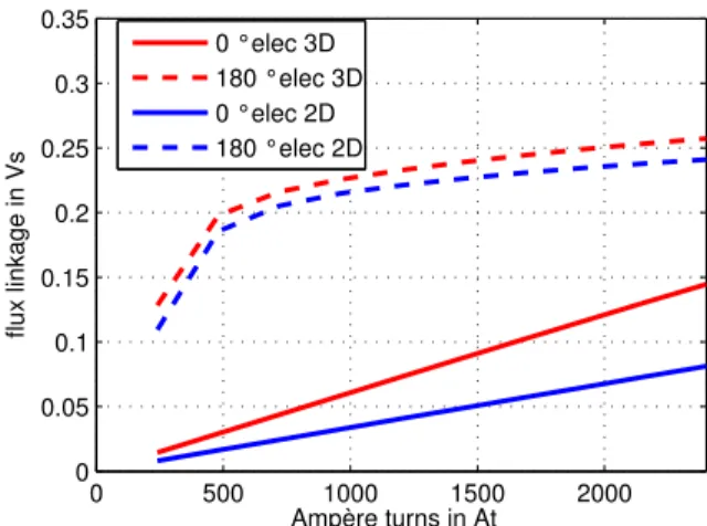
Due to little available space, the machine stack-length is very short compared to the stator diameter. Hence, electrical end-effects have to be considered during the design process and for drive simulations. Therefore, 2D and 3D finite element (FE) simulations were conducted in ANSYS. Fig. 1 and 2 show the simulation results of the phase flux linkage and the relative difference between 2D and 3D simulation at different current values in aligned and unaligned position. The difference of the flux linkage in the aligned position is ascribed mainly to end effects but also, for a small percentage, to differ- ent calculation methods used for 2D and 3D simulations. In [7]

similar differences in the aligned position were reported and explained with saturation effects at the ends of the structure.

This effect will be reviewed in more detail in future research.

However, the most significant impact of the end effects can be noticed in the unaligned position. In this case, the ratio between aligned and unaligned inductance in the saturation region drops from about 3 without end-effects to nearly 1.7 when end effects are considered. This leads to a significant reduction of the machine’s torque production capability.

During the electromagnetic design process the acoustic

behavior of the machine has to be reviewed as well. However,

within the limits of this development a complete vibroacoustic

simulation has not been carried out and certain assessments

were used.

(3)

0 500 1000 1500 2000 0

0.05 0.1 0.15 0.2 0.25 0.3 0.35

Ampère turns in At

flux linkage in Vs

0 °elec 3D 180 °elec 3D 0 °elec 2D 180 °elec 2D

Fig. 1. Comparison of fluxlinkage characteristic of the designed SRM over current in aligned position (180

elec) and unaligned position (0

elec) realted to one pole

0 500 1000 1500 2000

0 20 40 60 80 100

Ampère turns in At

relative difference in %

0 °elec 180 °elec

Fig. 2. Realtive difference between the flux linkage calculated by 2D and 3D methods in the aligned and unaligned position over current related to one pole

The design results of the batch process were analyzed with the finite element program ANSYS to identify the stator eigenfrequencies for different vibration modes. Furthermore, it is described in [8], that one can derive static and dynamic phase coupling vectors for each stator/rotor pole configuration, telling which multiple of the electrical frequency excites these vibration modes. The electrical frequency of the machine (1) depends on speed n and the number of rotor poles N r of the machine.

f el = n · N r (1)

After determining the eigenfrequencies of different vibration modes and with the help of the mentioned coupling vectors the designer can identify, which multiples of the electrical fre- quency might have a critical impact on the acoustic behavior.

In the chosen 6/4 design all vibration modes with a multiple of two and mode 2 can be excited by the radial forces. The vibration mode with the lowest eigenfrequeny is a mode 2 vibration with a frequency around 2.5 kHz as illustrated in

table III. Since mode 2 is directly excited by the radial forces of each phase and its eigenfrequency is well within the acoustic range, it is a critical mode and will be responsible for most of the machine’s vibration and noise. Furthermore, the other eigenmodes have far higher eigenfrequencies. So, they are less important because at these high frequencies less excitation occurs and human hearing system is less sensitive. To prevent excessive excitation, the mode 2 eigenfrequency should not correspond with the 1st, 2nd, 4th, 5th, 7th, 8th... harmonic of the electrical frequency [9]. Stiffening of the stator yoke can be be used to influence the eigenfrequencies mechanically and variation of control parameters may help to reduce certain excitation frequencies. The influence of the machine control will be shown in the next paragraph.

Altogether the electromagnetic batch design process has been described. To summarize, the influence of end effects on the design has been presented and methods to predict the acoustic behavior of the machine have been explained.

The machine dimensions of the final design are presented in table IV and a picture of the machine is shown in Fig. 3

IV. M ACHINE CONTROL INFLUENCE ON VIBRATIONS AND NOISE

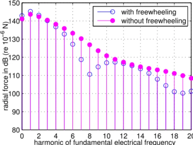
The choice of the converter topology and proper switching parameters is important for an acoustically optimized op- eration. To optain adequate controllability, a converter with asymmetrical half bridge topology is used rather than a one- switch design [10]. It offers the ability to operate the phase in a freewheeling mode to modify the spectrum of the radial force [9] and improve the acoustic performance of the drive.

In Fig. 4 the influence of a freewheeling period on the radial force waveform at one stator tooth is presented. It can be noticed, that besides a lower force maximum also the shape of the force differs, if a freewheeling period is used.

The changes have also noticeable effect on the radial force spectrum (see. Fig 5). A batch process can be used to find switching parameters leading to a reduced force amplitude at the critical eigenfrequencies of the structure.

V. T EST B ENCH

Measurements of the acoustic performance of the machine were conducted on two different test bench setups. First, the machine was tested using an eddy current brake test bench

TABLE III

C

ALCULATED EIGENFREQUENCIES OF DESIGNED MACHINE STATOR

eigen. freq. mode

0

mode

2

mode

4

6/4 13000 Hz 2500 Hz 11100 Hz

TABLE IV F

INAL MACHINE DIMENSIONS

Stack length 15 mm Machine diameter 120 mm

Rotor radius 30 mm

N

s

/N

r

configuration 6/4

(4)

Fig. 3. Interior view of the designed machine in the typical machine housing used in the application

0 60 120 180 240 300 360

0 30 60 90 120

rotor position in °elec

radial force in N

with freewheeling without freewheeling

Fig. 4. Simulated radial force waveforms using switching angle parameter sets with and without freewheeling

that does not produce additional acoustic noise or influences the application housing. The eddy current brake test bench is constructed vertically and is located under the machine under test. Additionally, a wooden box around the eddy current brake has been used to further dampen the remaining noise of the bearings and vibrations coupled in from the machine under test. Further information about the test bench can be found in [11].

0 2 4 6 8 10 12 14 16 18 20

80 90 100 110 120 130 140 150

harmonic of fundamental electrical frequency radial force in dB (re 10

−6

N)

with freewheeling without freewheeling

Fig. 5. Spectrum of the simulated radial force waveforms using switching angle parameter sets with and without freewheeling

The machine was also tested in the application housing itself in order to analyze the influence of the application structure on the noise transmission. In the dryer application the machine is located at the bottom pf the dryer housing. It is connected to the impeller of the dryer’s ventilation system and to the drum with a two stage belt gear in between. The machine’s axis is aligned horizontally in the application. A metal frame is used to connect the machine to the supporting part of the application.

VI. M EASUREMENT RESULTS AND ANALYSIS

During testing, the machine was operated at nominal speed and rated power. The results in Fig. 6. show the existence of the 4th, 5th, 7th and 8th harmonic of the fundamental electrical frequency, which is typical for the mode 2 excitation of a 6/4 machine as explained in the previous paragraph, compare [9]. The critical frequency in the spectrum, the 7th harmonic of the fundamental electrical frequency, is clearly visible. Modification of the switching angle and especially the use of a freewheeling period can reduce certain harmonics in the spectrum (Fig. 7) by 5dB, which is a bit less than expected based on simulation results. Interestingly, in the real housing, the significant 7th harmonic has not a great influence.

There the airborne sound is influenced by the 2nd harmonic of the fundamental electrical frequency, which is excited by the machine but does not lead to significant vibrations because it is too far below the mode 2 eigenfrequency (compare Fig. 6, Fig.

7 and Fig. 8). In fact the fundamental mechanical frequency at 50 Hz dominates the airborne sound. It is probably caused by unbalances in the mechanical system.

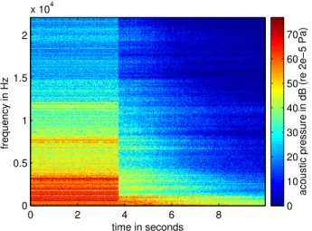
Also a run out test was performed where the electric excitation was switched off during operation. The results are shown in Fig. 9. Due to the disappearance of the multiples of the fundamental electrical frequency in the airborne sound, the overall noise of the machine can be rated as purely electromagnetically excited. Again, the 7th harmonic of the fundamental electrical frequency, which is caused by a mode 2

vibration, is visible in this measurement.

It can be concluded from the measurements that the drive fulfills the requirements of the application concerning speed

0 2 4 6 8 10 12 14 16 18 20

100 110 120 130 140 150

harmonic of fundamental electrical frequency surface acceleration in dB(re 10

−6

m/s

2

)

Fig. 6. Machine vibrations measured on the eddy current brake test bench

on the outside of the stator above the stator tooth without freewheeling period

(5)

0 2 4 6 8 10 12 14 16 18 20 100

110 120 130 140 150

harmonic of fundamental electrical frequency surface acceleration in dB (re 10

−6

m/s

2

)

Fig. 7. Machine vibrations measured on the eddy current brake test bench on the outside of the stator above the stator tooth with freewheeling period

0 2 4 6 8 10 12 14 16 18 20

30 40 50 60 70

harmonic of fundamental electrical frequency

acoustic pressure in dB (re 2e−5 Pa)

Fig. 8. Airborne sound measured for machine operation in the application housing using freewheeling operation

time in seconds

frequency in Hz

0 2 4 6 8

0 0.5 1 1.5 2

x 10

4

acoustic pressure in dB (re 2e−5 Pa)

0 10 20 30 40 50 60 70

Fig. 9. Airborne sound of the machine during a run out test from nominal speed on the eddy current break test bench

and rated output power. Regarding the acoustic analysis it can be said that the predicted mode 2 vibration of the machine is confirmed in the measurements and its contribution to the overall noise level can be reduced by control options. However, the significant impact of the fundamental electrical frequency and its 2nd harmonic in the airborne sound, which appeared in the application housing, was not predicted. It appears to be a resonance frequency of the application structure itself, which is excited via structure borne sound transmission an effect that was not simulated.

VII. C ONCLUSION

A design process for a switched reluctance drive to be used in household applications such as dryers was presented.

A way of optimizing drive efficiency and assessing machine vibrations by using machine design parameters was proposed.

Electromagnetic 2D and 3D finite element simulations were used to analyze the occurring end effects in the present pan cake design. Finally, measurement results were presented that approve the design and its function. The machine resonance frequency was determined. Adding a freewheeling period in the switching scheme had great influence on the vibrations of the machine. The significant excited frequencies are 4th,5th and 7th harmonic of the electrical fundamental frequency.

However, measurements of the machine installed in the ap- plication housing showed a influences of the 2nd harmonic on the airborne sound as it overlaps with the resonance frequency of the housing. Furthermore, the fundamental mechanical fre- quency dominates the acoustic impression of the application.

In future research, the mechanical coupling of machine and application housing has to be analyzed. Different active and passive damping methods of the machine vibrations have to be further investigated.

R EFERENCES

[1] T. J. E. Miller, Electronic Control of Switched Reluctance Machines.

Newnespress, 2001.

[2] T. Miller, “Optimal design of switched reluctance motors,” Industrial Electronics, IEEE Transactions on, vol. 49, no. 1, pp. 15–27, Feb 2002.

[3] J. Fiedler, K. Kasper, and R. De Doncker, “Acoustic noise in switched reluctance drives: an aerodynamic problem?” in Electric Machines and Drives, 2005 IEEE International Conference on, 15-15 May 2005, pp.

1275–1280.

[4] R. Inderka, “Direkte Drehmoment Regelung Geschalteter Reluktan- zantriebe,” Ph.D. dissertation, RWTH Aachen University, 2002.

[5] H. Brauer, M. Hennen, and R. De Doncker, “Multiphase Torque-Sharing Concepts of Predictive PWM-DITC for SRM,” in Power Electronics and Drive Systems, 2007. PEDS ’07. 7th International Conference on, 27-30 Nov. 2007, pp. 511–516.

[6] K. Kasper, J. Fiedler, D. Schmitz, and R. De Doncker, “Noise Reduction Control Strategies for Switched Reluctance Drives,” in Vehicle Power and Propulsion Conference, 2006. VPPC ’06. IEEE, 6-8 Sept. 2006, pp. 1–6.

[7] A. Michaelides and C. Pollock, “Effect of end core flux on the performance of the switched reluctance motor,” IEE Proceedings - Electric Power Applications, vol. 141, no. 6, pp. 308–316, 1994.

[Online]. Available: http://link.aip.org/link/?IEP/141/308/1

[8] J. Fiedler, K. Kasper, and R. De Doncker, “Spectral composition of stator vibrations resulting from modal superposition in SRM,” in Power Electronics, Machines and Drives, 2006. PEMD 2006. The 3rd IET International Conference on, 4-6 April 2006, pp. 216–220.

[9] J. O. Fiedler, “Design of Low-Noise Switched Reluctance Drives,” Ph.D.

dissertation, RWTH Aachen University, 2006.

(6)

[10] S. Ekram, N. Ravi, K. Rajagopal, and D. Mahajan, “Design and Development of a High Efficiency Switched Reluctance Motor for a Mixer-Grinder Application,” in Industrial Electronics Society, 2007.

IECON 2007. 33rd Annual Conference of the IEEE, 5-8 Nov. 2007, pp. 193–197.

[11] K. Kasper, M. Bosing, R. De Doncker, S. Fingerhuth, and M. Vorlander,

“Noise Radiation of Switched Reluctance Drives,” in Power Electronics

and Drive Systems, 2007. PEDS ’07. 7th International Conference on,

27-30 Nov. 2007, pp. 967–973.

數據

TABLE II
Fig. 1. Comparison of fluxlinkage characteristic of the designed SRM over current in aligned position (180 ◦ elec) and unaligned position (0 ◦ elec) realted to one pole 0 500 1000 1500 2000020406080100 Ampère turns in Atrelative difference in % 0 °elec 180
Fig. 5. Spectrum of the simulated radial force waveforms using switching angle parameter sets with and without freewheeling
Fig. 9. Airborne sound of the machine during a run out test from nominal speed on the eddy current break test bench

參考文獻

相關文件

The first row shows the eyespot with white inner ring, black middle ring, and yellow outer ring in Bicyclus anynana.. The second row provides the eyespot with black inner ring

In order to assess and appreciate the results of all these studies, and to promote further research on the Suan Shu Shu, an international Symposium was held on August 23-25

 develop a better understanding of the design and the features of the English Language curriculum with an emphasis on the senior secondary level;..  gain an insight into the

Students are asked to collect information (including materials from books, pamphlet from Environmental Protection Department...etc.) of the possible effects of pollution on our

Wang, Solving pseudomonotone variational inequalities and pseudocon- vex optimization problems using the projection neural network, IEEE Transactions on Neural Networks 17

Hope theory: A member of the positive psychology family. Lopez (Eds.), Handbook of positive

volume suppressed mass: (TeV) 2 /M P ∼ 10 −4 eV → mm range can be experimentally tested for any number of extra dimensions - Light U(1) gauge bosons: no derivative couplings. =>

We explicitly saw the dimensional reason for the occurrence of the magnetic catalysis on the basis of the scaling argument. However, the precise form of gap depends