台灣師範大學機電科技學系 C. R. Yang, NTNU MT
-1-
Chapter 3
Harmonically Excited Vibration
3
台灣師範大學機電科技學系C. R. Yang, NTNU MT
-2-
Learning Objectives
Find the response of undamped and viscously damped single-DOF systems subjected to different types of harmonic force, including base excitation and rotating unbalance
Distinguish between transient, steady-state, and total solutions
Understand the variations of magnification factor and phase angles with the frequency of excitation and the phenomena of resonance and beats
Find the response of systems involving Coulomb, hysteresis, and other types of damping
Identifyself-excited problemsand investigate their stability aspects
Derivetransfer functions of systems governed by linear differential equations with constant coefficients
台灣師範大學機電科技學系 C. R. Yang, NTNU MT
-3-
Learning Objectives
Solve harmonically excited single-DOF vibration problems using Laplace transforms
Derive frequency transfer functionfrom the general transfer function and represent frequency-response characteristicsusingBode diagrams
Solve harmonically excited vibration response using MATLAB
台灣師範大學機電科技學系 C. R. Yang, NTNU MT
-4-
Chapter Outline
3.1 Introduction 3.2 Equation of Motion
3.3 Response of an Undamped System Under Harmonic Force 3.4 Response of a Damped System Under Harmonic Force 3.5 Response of a Damped System Under
3.6 Response of a Damped System Under the Harmonic Motion of the Base
3.7 Response of a Damped System Under Rotating Unbalance 3.8 Forced Vibration with Coulomb Damping
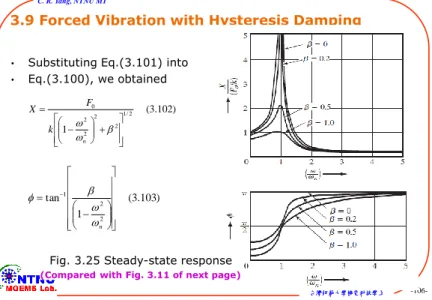
3.9 Forced Vibration with Hysteresis Damping 3.10 Forced Motion with Other Types of Damping 3.11 Self-Excitation and Stability Analysis
t
ei
F t F() 0
台灣師範大學機電科技學系 C. R. Yang, NTNU MT
-5-
Chapter Outline
3.12 Transfer-Function Approach 3.13 Solutions Using Laplace Transforms 3.14 Frequency Transfer Functions
台灣師範大學機電科技學系 C. R. Yang, NTNU MT
-6-
3.1
Introduction
3.1
台灣師範大學機電科技學系 C. R. Yang, NTNU MT
-7-
3.1 Introduction
•Forced vibrations occurs whenever external energy is always supplied to the system during vibration.
•The external force can be supplied through either an applied force or an imposed displacement excitation, which may be harmonic, nonharmonic but periodic, nonperiodic, or random in nature.
•
The response of a system to a harmonic excitation is called harmonic response.The harmonic excitations is the form:where F0is the amplitude, is the frequency, and is the phase angle of the harmonic excitation. The value of depends on the value of F(t) at t=0 and is usually taken to be zero.
0 0 0
( )
( ) i t ( ) cos( ) ( ) sin( )
F t F e or F t F t or F t F t
台灣師範大學機電科技學系 C. R. Yang, NTNU MT
-8-
3.1 Introduction
•Transient response is defined as the response of a dynamic system to suddenly applied nonperiodic excitations.
•Under a harmonic excitation, the response of the system will also be harmonic.
•If the frequency of excitation coincides with the natural frequency of the system, the response will be very large, which is known as resonance and should be avoided.
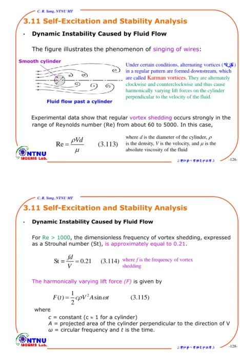
•The vibration produced by a unbalanced rotating machine, the oscillation of a tall chimney (煙囪) due to vortex (渦流) shedding (旋渦脫落)in a steady wind, and the vertical motion of an automobile on a sinusoidal road surface are examples of harmonically excited vibration.
台灣師範大學機電科技學系 C. R. Yang, NTNU MT
-9-
3.2
Equation of Motion
3.2
台灣師範大學機電科技學系C. R. Yang, NTNU MT
-10-
3.2 Equation of Motion
•From the figure below, the equation of motion using Newton’s Second Law of Motion states that
•The homogeneous solution is obtained from the homogeneous equation(the free vibration)
( ) (3.1) mx cx kx F t
0 (3.2) mx cx kx
A spring-mass-damper system To find the homogeneous solution xh
and particular solution xp, and general solution as x(t)=xh+xp
As seen in Section 2.6.2, this free vibration dies out with time under each of the three possible conditions of damping (underdamping, critical damping, and overdamping) and under all possible initial conditions
台灣師範大學機電科技學系 C. R. Yang, NTNU MT
-11-
3.2 Equation of Motion
•The variations of homogeneous and general solutions with time for a typical case are shown in the figure below.
Homogenous and general solutions of Eq. (3.1) for an underdamped case Homogeneous solution: Transient vibration
Particular solution:Steady-state vibration
General solution
(the free-vibration part)
(the force-vibration part)
Xh(t) dies out and x(t) becomes xp(t) after time The rate at which the
transient motion decays depends on the values of the system parameters k, c, and m
台灣師範大學機電科技學系 C. R. Yang, NTNU MT
-12-
3.3 Response of an Undamped System Under Harmonic Force
3.3
台灣師範大學機電科技學系 C. R. Yang, NTNU MT
-13-
3.3 Response of an Undamped System Under Harmonic Force
•Consider an undamped systemsubjected to a harmonic force. If a harmonic force acts on the mass m of the system,
•The homogeneous solutionis given by:
( ) 0cos F t F t
) 3 . 3 (
0cos t F kx x
m
) 4 . 3 ( sin cos
)
(t C1 t C2 t
xh n n
2 /
)1
/ (k m
n
where is the natural frequency
( mx cx kx 0 (3.2))
台灣師範大學機電科技學系 C. R. Yang, NTNU MT
-14-
3.3 Response of an Undamped System Under Harmonic Force
•Because the exciting force and particular solution is harmonic and has the same frequency, we can assume a solution in the form:
Thus, the total solution of Eq. (3.3) is where X is the Max. amplitude of xp(t)
) 5 . 3 ( cos
)
(t X t
xp
0 0
2 2
2
3 6
1 1
/ st ( . )
n
F F k
X k m m
k
k
stF0/
where denotes the static deflection
0
1 2 2
( ) h( ) p( ) cos n sin n F cos (3.7)
x t x t x t C t C t t
k m
代入(3.3)式,等號兩邊做係數比較 求出X (待定係數法)
台灣師範大學機電科技學系 C. R. Yang, NTNU MT
-15-
3.3 Response of an Undamped System Under Harmonic Force
•Using initial conditions
Hence
The Max. amplitude in Eq. (3.6) can be expressed as ) 8 . 3 (
, 2 0
2 0 0 1
n
C x m k x F
C
) 9 . 3 ( cos
sin cos
) (
2 0
0 2
0 0
m t k
F
x t m t
k x F t
x n
n n
2
1 (3.10)
st 1
n
X
0 0
0 0
( ) ( ) x t x and x t x
The ratio of the dynamic to the static amplitude of the motion is called magnification factor, amplification factor, or amplitude ratio
/ st X
台灣師範大學機電科技學系 C. R. Yang, NTNU MT
-16-
3.3 Response of an Undamped System Under Harmonic Force
•The quantity is called the magnification factor, amplification factor, or amplitude ratio.
•The variation of the amplitude ratiowith the frequency ratiois shown in the figure.
•The response of the system can be identified to be of three types.
X/st
Magnification factor of an undamped system
1 0 1
2 1
3 1
.
.
.
n
n
n
2
1
st 1
n
X
Case 1
Case 2 Case 3
台灣師範大學機電科技學系 C. R. Yang, NTNU MT
-17-
3.3 Response of an Undamped System Under Harmonic Force
•Case 1:
When 0 < < 1, the denominator in Eq.(3.10) is positive and the response is given by Eq.(3.5) without change. The harmonic response of the system is in phase with external force, shown in figure.
/ n
Harmonic response when 0/n1
2
1 (3.10)
st 1
n
X
) 5 . 3 ( cos
)
(t X t
xp
相角差=0o
台灣師範大學機電科技學系 C. R. Yang, NTNU MT
-18-
3.3 Response of an Undamped System Under Harmonic Force
•Case 2:
When > 1, the denominator in Eq.(3.10) is negative and the steady-state solution can be expressed as
where the amplitude is redefined as
The response of the system to a harmonic force of very high frequency is close to zero
/ n
) 11 . 3 ( cos )
(t X t
xp
) 12 . 3 ( 1
2
n
X st
Harmonic response when /n1
相角差=180o ( n , X0)
cos( )
X t
台灣師範大學機電科技學系 C. R. Yang, NTNU MT
-19-
3.3 Response of an Undamped System Under Harmonic Force
•Case 3:
When , the amplitude X given by Eq.(3.10) or (3.12) becomes infinite. The forcing frequencyis equal to the natural frequency nof the system is called resonance.
The total response if the system at resonance is rewrite Eq. (3.9) as / n 1
0 0 0
0 2 2
0 0
2 0
0 2
0
( ) cos sin cos (3.9)
cos sin (cos cos )
cos cos
cos sin
1 ( )
n n
n
n
st
n n
n
n n
n n
n
F x F
x t x t t t
k m k m
x t x t t t
x t x
m
t F k
t t
(3.13)
台灣師範大學機電科技學系 C. R. Yang, NTNU MT
-20-
與時間成正比關係
台灣師範大學機電科技學系 C. R. Yang, NTNU MT
-21-
Harmonic response when
/
n 1 ( . ., i e
n)
0
( ) 0cos sin sin (3.15)
2
st n
n n n
n
t x t x t x t t
台灣師範大學機電科技學系 C. R. Yang, NTNU MT
-22-
3.3 Response of an Undamped System Under Harmonic Force
•Total Response
The total response of the system, Eq.(3.7) or Eq.(3.9), can also be expressed as
( ) cos( ) 2cos ; for 1 (3.16)
1 n
n
st
n
x t A t t
1 2
0
( ) cos n sin n 2cos (3.7)
x t C t C F t
t k m
•Or
And
( ) cos( ) 2cos ; for 1 (3.17)
1
st
n n
n
x t A t t
( ) cos( ) cos cos( ) 2 cos
1
n n
st
n
x t A t X t A t t
台灣師範大學機電科技學系 C. R. Yang, NTNU MT
-23-
3.3 Response of an Undamped System Under Harmonic Force
( ) cos( ) 2cos ; for 1 (3.16)
1 n
n
st
n
x t A t t
台灣師範大學機電科技學系 C. R. Yang, NTNU MT
-24-
( ) cos( ) 2cos ; for 1 (3.17)
1
st
n n
n
x t A t t
The complete motion can be expressed as the sum of two cosine curves of different frequencies.
台灣師範大學機電科技學系 C. R. Yang, NTNU MT
-25-
3.3 Response of an Undamped System Under Harmonic Force
•Beating Phenomenon
If the forcing frequency is close to, but not exactly equal to, the natural frequency of the system, beating may occur.
The phenomenon of beating can be expressed as Eq. (3.18) from Eq.
(3.9) under the initial conditions of :
0 0 0
0 2 2
0
2 2
0
2 2
(cos
( ) cos sin cos (3.9)
( )
( )
(3.18 cos )
(2 sin sin )
2 )
2
n
n n
n n
n
n
n
t t
t t
F x F
x t x t t t
k m k m
F m
F m
0 0 0
x x
台灣師範大學機電科技學系 C. R. Yang, NTNU MT
-26- 0
2 2
0
( )
( ) (2 ) (3.18)
/ (
s
3.22)
si in
n 2 2
s n 2 s ni i
n
n
F m n
x t
F t
t
m t
t
2 2
2 (3.19) 2 (3.20) (3.19) (3.20)
4
n n n
n
數值小、週期大 數值大、週期小
波的振幅
波的振幅
the period of beating
台灣師範大學機電科技學系 C. R. Yang, NTNU MT
-27-
3.3 Response of an Undamped System Under Harmonic Force
•Beating Phenomenon
The time between the points of zero amplitude or the points of maximum amplitude is called the period of beatingand is given by
The frequency of beating defined as
b 2
n
2 2 2
(3.23) 2
2
2 1
b
b n
2 (3.19)n n
台灣師範大學機電科技學系 C. R. Yang, NTNU MT
-28-
3.3 Response of an Undamped System Under Harmonic Force
Example 3.1 Plate Supporting a Pump
A reciprocating pump, having a mass of 68kg, is mounted at the middle of a steel plate of thickness 1cm, width 50cm, and length 250cm, clamped along two edges as shown in Figure. During operation of the pump, the plate is subjected to a harmonic force, F(t) = 220 cos 62.832t N. Find the amplitude of vibration of the plate.
台灣師範大學機電科技學系 C. R. Yang, NTNU MT
-29-
3.3 Response of an Undamped System Under Harmonic Force
Example 3.1 Plate Supporting a Pump Solution
The plate can be modeled as a fixed-fixed beam having Young’s modulus (E) = 200GPa, length = 250cm, and area moment of inertia,
The bending stiffness of the beam is given by:
2 2 3 9 4
1(50 10 )(1 10 ) 41.667 10 m
I12
(E.1) N/m
82 . 102400 )
10 250 (
) 10 667 . 41 )(
10 200 )(
192 ( 192
3 2
9 9
3
l k EI
a=50 cm
b=1 cm plate
1 3
I12ab
台灣師範大學機電科技學系 C. R. Yang, NTNU MT
-30-
3.3 Response of an Undamped System Under Harmonic Force
Example 3.1 Plate Supporting a Pump Solution
Thus,
0
2 2
220 102400.82 68(62.832) 0.00132487 m 1.32487 mm (E.2) X F
k m
0
2
( . ) 3 6 X F
k m
0 220 68
102400.82 / 62.832 /
F N
m kg
k N m
rad s
The negative sign indicates that the response x(t) of the plate is out of phasewith the excitation F(t)
台灣師範大學機電科技學系 C. R. Yang, NTNU MT
-31-
3.4 Response of a Damped System Under Harmonic Force
3.4
台灣師範大學機電科技學系C. R. Yang, NTNU MT
-32-
3.4 Response of Damped System Under Harmonic Force
2
cos
sin
0cos ( .3 26) X km
t c
t F
t•If the forcing function is given by
•The equation of motion becomes
•The particular solution of Eq. (3.24) is
•By substituting Eq.(3.25) into Eq.(3.24)
•Using trigonometric relations,
( ) 0cos F t F t
0 3 24
cos ( . ) mx cx kx F t
3 25 ( ) cos( ) ( . ) x tp X t
cos( ) cos cos sin sin
sin( ) sin cos cos sin
t t t
t t t
台灣師範大學機電科技學系 C. R. Yang, NTNU MT
-33-
•Equating the coefficients of cost and sint on both sides of the resulting equation, we obtain
2
0 2
cos sin
sin cos 0 (3.27)
X k m c F
X k m c
1 2 2
2
2 2 2 1/ 2
0 0
2
2
0 0
22 2
0
2
2 1/
sin t
sin cos 0 tan
cos
cos
(3 [
.28
an ( )
[ (
( ) ]
sin
) ] )
k m c c
k m
if A k m c
F
k m A X F
k m c
k m c c
A
F F
c k m
F
A k m c
A A
3 25 ( ) cos( ) ( . )
x tp X t just find X and
The particular solution
=Steady-state response
(3.29)
台灣師範大學機電科技學系 C. R. Yang, NTNU MT
-34-
3.4 Response of Damped System Under Harmonic Force
•The figure shows typical plots of the forcing function and steady- state response.
(a) Graphical representation (b) Vectorial representation for Eq.(3.26)
2
0 2
0
3 26
cos sin cos ( . )
cos cos sin cos
X k m t c t F t
kX t m X t c X t F t
t
t t
台灣師範大學機電科技學系 C. R. Yang, NTNU MT
-35-
3.4 Response of Damped System Under Harmonic Force
•Dividing both the numerator and denominator of Eq. (3.28) by k and making the following substitutions
m; k
n
2 2 ; 2 n;
c n
c c c c
c m mk m
0; k F
st
n
r
0 0
1 2 1 2
2 2
2 2 2 2 2 2
1 2 1 2
2 2
2 2 2 2
2 2 2
1 2 1 2
2 2
2 2 2
2 2
2 2
2 2
3 28
4
1 1
2
11
4
1
1
/ /
/ /
/ /
/ ( . )
( )
st st
n
st st
n
s
n
t
F F k
X
k m c k m c
c
k
m
k k k
r r
X
mk
1 2 1 2
2 2
2 2 2 2 2
2 2
1 3 30
4 1 2
/ / ( . )
( )
n n
r r
Frequency ratio:
Undamped natural frequency:
Deflection under the static force:
台灣師範大學機電科技學系 C. R. Yang, NTNU MT
-36-
1 1
2 2
1 1
2 2
1 1
2
2 2
2 2
3 29 1
2 2
1 1
1 1 3 31
tan tan
( )
t
( . )
an ta
tan tan
n
( . )
n n
c c k
k m m k
m
mk k k
m k m k
r r
m; k
n
2 2 ; 2 n;
c n
c c c c
c m mk m
0; k F
st
n
r
Frequency ratio:
Undamped natural frequency:
Deflection under the static force:
台灣師範大學機電科技學系 C. R. Yang, NTNU MT
-37-
3.4 Response of Damped System Under Harmonic Force
•The following characteristics of the magnification factor (M=X/st) can be noted from the figure as follows:
2 1 2
2 2 2
2 2
2 1 2
2 2
1 1 4
1 3 30
1 2
/
/ ( . )
( )
st
n n
X
r r
2
1 (3.10)
st 1
n
X
0 if
台灣師範大學機電科技學系 C. R. Yang, NTNU MT
-38-
3.4 Response of Damped System Under Harmonic Force
1. For an undamped system , Eq.(3.30) reduces to Eq.(3.10), and as .
2. Any amount of damping reduces the magnification factor (M) for all values of the forcing frequency.
3. For any specified value of r, a higher value of damping reduces the value of M.
4. In the degenerate (退化的) case of a constant force (when r = 0), the value of M = 1.
) 0 (
M r 1 ( 0)
台灣師範大學機電科技學系 C. R. Yang, NTNU MT
-39-
3.4 Response of Damped System Under Harmonic Force
5. The reduction in M in the presence of damping is very significant at or near resonance.
6. The amplitude of forced vibration becomes smaller with increasing values of the forcing frequency (that is, as ).
7. For , the maximum value of Moccurs when
which can be seen to be lower than the undamped natural frequency nand the damped frequency
0
M r
0 1
2 0.71
2 2
1 2 or n 1 2 (3.32)
n
r
1 2
d n
(see Problem 3.32)
台灣師範大學機電科技學系 C. R. Yang, NTNU MT
-40-
3.4 Response of Damped System Under Harmonic Force
8. The maximum value of X (when ) is given by:
and the value of X at by
9. For when r = 0. For , the graph of M monotonically decreases with increasing values of r.
1 2 2
r
2
2 2 1/ 2 max 21 (3.30)
1 (2
1 (3.
) 2
33) 1
st st
X X
r r
2
2 2 1/ 21 (3.30) 1 . .,
(3.34) (
1 (2 2
1)
) s n
t t
n s
X i e
r r
X r
, 0
1 2
dM
dr 1
0.71
2
n
(可實驗求得X與,代入求得,反之亦然 )
台灣師範大學機電科技學系 C. R. Yang, NTNU MT
-41-
3.4 Response of Damped System Under Harmonic Force
• The following characteristics of the phase angle can be observed from the figure and Eq.(3.31) as follows:
1
2 2
1 2
2 1
2 3 31
1 tan
tan ( . )
n n
r r
●
台灣師範大學機電科技學系 C. R. Yang, NTNU MT
-42-
3.4 Response of Damped System Under Harmonic Force
1.
For an undamped system , Eq.(3.31) shows that the phase angle is 0 for 0 < r < 1 and 180° for r > 1.This implies that the excitation and response are in phasefor 0 < r < 1 and out of phase for r > 1 when .2. For and 0 < r < 1, the phase angle is given by 0 < Φ < 90°, implying that the response lagsthe excitation.
3. For and r > 1, the phase angle is given by 90° < Φ < 180°, implying that the response leadsthe excitation.
) 0 (
0
0
0
台灣師範大學機電科技學系 C. R. Yang, NTNU MT
-43-
3.4 Response of Damped System Under Harmonic Force
4. For and r = 1, the phase angle is given by Φ = 90°, implying that the phase difference between the excitation and the response is 90°.
5. For and large values of r, the phase angle approaches 180°, implying that the response and the excitation are out of phase.
0
0
台灣師範大學機電科技學系 C. R. Yang, NTNU MT
-44-
3.4 Response of Damped System Under Harmonic Force
• Total response: The complete solution is For an underdamped system,
) 35 . 3 ( ) cos(
) cos(
)
(t X0e t0 X t
x d
nt
) 36 . 3 ( 1 2 n
d
( ) h( ) p( ) x t x tx t
270 325
( ) h p .( . ) .( . )
xt x x Eq Eq
0
1 2 1 2 1 2
2 2 2 2 2 2
2 2 2 2 2
2 2
4 1
1
3 28 3 30
2
/ / /
( ( . )
) )
st st ( .
n n
X F
k m c r r
1 1 1
2 3 29 2 2 2 3 3
2 2
1 1
tan ( . ) = tan n tan 1 ( . )
n
c r
k m r
1 2
(whered n)
台灣師範大學機電科技學系 C. R. Yang, NTNU MT
-45-
0 0 0
0
0 0 0 0
0
0 3 36
( )
( )
cos cos
cos sin sin ( . )
n d
x X X
X X X
t x
x t x
X0and 0can be determined from the initial conditions, , Eq.(3.35) yields
0 0
( 0) ( 0) x t x and x t x
) 35 . 3 ( ) cos(
) cos(
)
(t X0e t0 X t
x nt d
The solution of Eq.(3.36) gives X0and 0as 解聯立
方程式
(Practice by yourself)
台灣師範大學機電科技學系 C. R. Yang, NTNU MT
-46-
3.4 Response of Damped System Under Harmonic Force
Example 3.3
Total Response of a System
Find the total responseof a single degree of freedom system with m
=10kg, c = 20 N-s/m, k = 4000 N/m, x0= 0.01 m, under the following conditions:
a. An external force acts on the system with and .
a. Free vibration with F(t) = 0.
00 x
t F t
F() 0cos N
0100 rad/s F
10
台灣師範大學機電科技學系 C. R. Yang, NTNU MT
-47-
3.4 Response of Damped System Under Harmonic Force
Example 3.3 Total Response of a System Solution
a. From the given data,
0 4000
10
100 4000
20
2 2 4000 10
2 2
10 20
2 2 2 2
2 2
20 0 025
0 05
1 1 0 05 20 19 974984 0 5
0 025
0 03326
1 2 1 0 05 2 0 5 0 5
rad/s . m
.
. . rad/s
.
. . m (E.1)
. . .
c
n k
n m
F
st k
c c
c km
d n
st
r X
r r
0 0
( ) ntcos( d ) cos( ) (3.35)
x t X e
t
X
t台灣師範大學機電科技學系 C. R. Yang, NTNU MT
-48-
3.4 Response of Damped System Under Harmonic Force
Example 3.3
Total Response of a System Solution
We have
Using initial conditions , Eq.(3.36)yield:
(E.2) 814075
. 5 3 . 0 1
5 . 0 05 . 0 tan 2 1
tan1 2 2 1 2
r
r
0 0
0 0
0 01 0 03326 0 997785
0 023186
. cos ( . )( . )
cos . (E.3)
X X
(E.4) )
814075 . 3 sin(
) 10 )(
03326 . 0 (
sin ) 974984 . 19 ( cos ) 20 )(
05 . 0 (
0 0 0 0 0
X X
0 and 01 .
0
00
x
x
台灣師範大學機電科技學系 C. R. Yang, NTNU MT
-49-
3.4 Response of Damped System Under Harmonic Force
Example 3.3 Total Response of a System Solution
Substituting Eq.(E.3) into (E.4),
Hence,
(E.5) 002268
. 0 sin 0
0
X
(E.7) 586765
. 5
0978176 . cos 0 tan sin
0
0 0
0 0 0
X X
( cos ) ( 0sin 0)2
1/2 0.023297 (E.6)2 0 0
0 X X
X
台灣師範大學機電科技學系 C. R. Yang, NTNU MT
-50-
3.4 Response of Damped System Under Harmonic Force
Example 3.3 Total Response of a System Solution
b. For free vibration, the total response is
Using the initial conditions,
(E.9) 010012 . 974984 0
. 19
01 . 0 20 05 . 01 0 . 0
2 / 2 1 2
2 / 2 1
2 0 0
0
d nx x
X
0 0
( ) ntcos( d ) (E.8) x t X e t
1 0 0 1
0
0
0 05 20
2 865984 19 974984
tan tan . . (E.10)
.
n
d
x x
x
0 and 01 .
0
00
x
x
(See Eqs.(2.73) and (2.75)))台灣師範大學機電科技學系 C. R. Yang, NTNU MT
-51-
3.4 Response of Damped System Under Harmonic Force
• Quality factor and bandwidth:
For small values of damping ,
From figure, R1and R2, where the amplification factor falls to , are called half-power pointsbecause the power absorbed (W) by the damper, responding harmonically at a given frequency, is proportional to the square of the
amplitude (See Eq.(2.94))
0 05
( . )
) 38 . 3 ( 2
1
max
X Q X
st n st
The value of the amplitude ratio at resonance is called as quality factor or Q factor of the system
) 39 . 3
2
( X c W
2 Q
2 max
1 (3.33)
2 1
st
X
台灣師範大學機電科技學系 C. R. Yang, NTNU MT
-52-
2
0
( )
1 (3.38)
2 Q
2 2 2
2 2 (1r) (2r)