行政院國家科學委員會專題研究計畫 成果報告
數位典藏資訊之版權保護與驗證技術之研究(三)
計畫類別: 個別型計畫 計畫編號: NSC93-2422-H-009-001- 執行期間: 93 年 03 月 01 日至 94 年 02 月 28 日 執行單位: 國立交通大學資訊科學學系(所) 計畫主持人: 蔡文祥 共同主持人: 吳大鈞 計畫參與人員: 翁連奕、莊岳城、洪世結 報告類型: 完整報告 處理方式: 本計畫可公開查詢中 華 民 國 94 年 5 月 31 日
行政院國家科學委員會補助專題研究計畫
期末執行報告
※※※※※※※※※※※※※※※※※※※※※※※※※※
※ ※
※
※
※ ※
※
※
※ ※
數位典藏資訊之版權保護與驗證技術之研究(三)
A Study on Copyright Protection & Authentication Techniques
for Digital Information Archiving(3)
※※※※※※※※※※※※※※※※※※※※※※※※※※
計畫類別:個別型計畫
計畫編號:NSC92-2422-H-009-010
執行期間:93 年 3 月 1 日至 94 年 2 月 28 日
計畫主持人:臺中健康暨管理學院校長兼交通大學講座教授蔡文祥教授
共同主持人:高雄第一科技大學吳大鈞副教授
執行單位:國立交通大學資訊科學系
中 華 民 國 94 年 05 月 25 日
目錄
第一部份:期末執行成果略述………01 第二部分:計畫技術內容概述………02 一、黑白影像之資訊隱藏技術與應用之開發………02 二、公文影像之資訊隱藏技術與應用之開發………03 三、影像認證中心工作的細化與運作………04 第三部份:已開發技術詳述………05Chapter 1 Development of Data Hiding Technique and Application for Binary Images — Data Hiding Technique for Binary Images……….06
— A New Image Authentication Technique for Binary Images………...…..21
Chapter 2 Development of Data Hiding Technique and Application for Binary Document Images — Hiding Authenticable General Digital Information behind Binary Document Images With Reduced Distortion.………... ... ... ... ... ... ... ... ... ... ... ... ... ... ... ... ...41
— A New Approach to Authentication of Binary Document Images for Multimedia Communication with Distortion Reduction and Security Enhancement………51
Chapter 3 Image or Video Authentication for Copyright Claim………58
附件一:參加「第二屆數位典藏技術研討會」發表之論文 “Hiding Authenticable General Digital Information behind Binary Images with Reduced Distortion” ………..……….…61
“Using a Human Visual Model and Boundary Lines for Embedding Robust Watermarks in Large Images” ………..….….….….….….….….…...69
第一部份 期末執行成果略述
本計畫「數位典藏資訊之版權保護與驗證技術之研究」執行時間為93 年 3 月 1 日至 94 年 2 月28 日,須完成之工作項目包括: 1. 黑白影像之資訊隱藏技術與應用之開發 2. 公文影像之資訊隱藏技術與應用之開發 3. 影像認證中心工作的細化與運作 本計畫團隊經過一年積極的研究,已經完成上述全部工作。 此外,在去年8 月 31 日,本計畫團隊與推廣辦公室合辦「數位典藏專業培訓課程系列四—數 位典藏版權資訊研討會」,邀集數位典藏單位以及相關學術單位共二十多個單位參加。除了講解 版權保護與驗證技術之發展歷程及現況之外,同時也發給參加人員「資訊保護家 3.0 版」應用軟 體,讓各單位能在現場實際操作及發現問題。本計畫團隊也針對此次蒐集的問題詳加研究並予以 改進。 而在去年8 月 5 日、6 日由數位典藏技術分項所舉辦的第三屆數位典藏技術研討會中,本計畫發表了二篇論文:「Copyright Protection by Watermarking for Color Images against Rotation and Scaling Attacks Using Peak Detection and Synchronization in Discrete Fourier Transform Domain」與 「Using a Human Visual Model and Boundary Lines for Embedding Robust Watermarks in Large Images」,其詳細內容如附件一。 此外依所研究的影像認證中心之運作,本計畫在二年前成立了交通大學影像認證中心,而在 本年度內,本中心設計了註冊證明書(詳見附件二),作為典藏單位到認證中心來註冊的憑據。 由於目前本計畫正積極的發展「資訊保護家 4.0 版」軟體,希望能將這一年所發展的技術整 合至軟體中,並在今年再次舉辦軟體訓練課程,讓本計畫團隊所發展的資訊保護技術能對數位典 藏單位有實質上的幫助。
第二部分:計畫技術內容概述
在技術部分,本計畫所需完成之工作項目有黑白影像之資訊隱藏技術與應用之開發、公文影 像之資訊隱藏技術與應用之開發,以及影像認證中心之工作的細化與運作等四項,在這個部分將 針對這些技術作概略的說明。 一、 黑白影像之資訊隱藏技術與應用之開發 黑白影像的每個像素只能代表黑白兩色,故又稱二元(bi-level)影像。一般灰階及全彩影像 也可以藉由臨界值法或網孔法(dithering)處理轉換成黑白影像。一般來說,二值化的目的是要 將影像中的物體和背景分離,常應用在文字影像辨識上。浮水印相關的應用必須在影像中修改像 素值才能達到植入資料的目的。黑白影像像素值代表兩極端對比顏色,若隨意改變其像素值,很 容易觀察出影像的變化。所以在黑白影像中隱藏資訊的困難度很高。研究如何在不容易被人眼察 覺的地方改變黑白像素值,進而達到植入資料的目的,是我們此一研究項目的目標。另外,為了 植入更多的資料,就必須改變更多的黑白像素值,但是改變越多黑白像素值,影像的品質就會變 的更糟、失真更多;相反的,如果要維持影像的品質,植入的資料就會變的較少。這是個兩難的 問題,也是在計畫研究中要克服的地方,希望能做到植入的資料量既多,影像的失真亦少。 黑白影像之資訊隱藏技術與應用之開發主要進行下列兩項工作: A. 以資料隱藏技術將註解性資料植入黑白影像中 在隱藏過程中,我們先將黑白影像切割成3×3區塊。每一區塊最多藏入兩個位元。接 下來我們會判斷此區塊是否適合藏入資訊,若此區塊經判斷的結果不適合藏入資訊則不藏 入任何的資料;若此區塊屬於可藏的區塊,則先判斷區塊中黑色像素個數,再視要隱藏的 資料值為何,依據一先訂好的索引表格,調整區塊中黑色像素個數,以增加一個黑色像素、 減少一個黑色像素或不改變,來對應其要隱藏的資料值。而在增加或減少黑色像素時,需 要找不易被視覺察覺出來的地方才藏入,如黑色區塊或白色區塊的角點,以達到嵌入浮水 印或註解資料而不被察覺之目的。對已隱藏資料之黑白影像,若要將所隱藏的資料抽取出 來,我們先將黑白影像切成3×3二元區塊,依據先前植入資料的編碼規則,一一對每一3×3 區塊進行處理,判斷該區塊中黑色像素的個數,便可分別得到其隱藏的資料。如此做到所 有區塊都判斷完畢,抽取隱藏資料工作便告結束,而可得到完整的註解和典藏機構標記。 B. 以資料隱藏技術將可供防竄檢驗的易碎浮水印植入黑白影像中 一般來說,黑白影像中可隱藏的資料量不多,只能藏小型典藏機構標記或少量註解資 料,而在驗證資料時也必須以較大區塊為判斷單位。本計畫也將依此性質提出對黑白影像 植入認證用資訊的技術,利用這些認證用資訊,來驗證此黑白影像有無遭到竄改。 首先我們擬將將黑白影像切成不重疊的 9×9 區塊,再將各 9×9 區塊細分成九個 3×3 之二元區塊,接著從中先選出一個“可重新排列內容像素”的 3×3 區塊,再計算其餘 8 個區 塊的標準差值,以此標準差值為相關的認證資料,重新排列可重排的區塊的像素位置,以 不同的排列方式對應植入資料的認證資訊,來達到植入認證用資訊的目的。而所謂“選擇可重新排列內容像素”的 3×3 區塊,是為了控制植入認證資訊後的影像品質。其方法是先用一 個所謂“簡化半色調灰階函數”(reduced halftone gray function),給每一 3×3 區塊一個對應
的灰階值,算出來的灰階值越大代表該3×3 區塊黑色像素個數越少;基於此,我們將選擇 黑色像素越多的區塊來做白色像素位置的重新排列,以及選擇白色像素越多的區塊來做黑 色像素位置的重新排列,以便讓處理過的影像失真較少。當一張已植入認證資料的黑白影 像要做影像驗證時,我們首先將黑白影像切成9×9 區塊,再將此 9×9 區塊細分 3×3 二元區 塊,之後計算3×3 區塊的黑像素個數,再利用“簡化半色調灰階函數”算出對應的灰階值, 選出“可重新排列內容像素”的一個 3×3 區塊,以其排列方式計算得到認證的資料,最後比 對由其他8 個 3×3 區塊計算標準差得到的認證資料,即可知道該 9×9 區塊有無遭到竄改: 兩者認證資料相同代表未遭到竄改。 二、 公文影像之資訊隱藏技術與應用之開發 公文影像是指印刷或打字所成之文書稿件,再將其掃描或數位化後所得之影像。本計畫將探 討以TIFF檔案方式存放之黑白公文影像之資料隱藏及影像認證技術。此外公文影像的最大特色是 有大面積的白色區塊,因此,若在背景單調之區域隨意改變其像素值,則更容易觀察出影像的變 化,故如何避開此種區塊而行藏入動作為其重點。不像一般的影像是針對圖片做處理,公文影像 另一特色是針對字,只要隨意改變字的小小區塊的像素值,就會使原本清晰可見的字元產生模糊 不清的現象,甚至可能會有錯誤情況發生。 公文影像之資訊隱藏技術與應用之開發主要進行下列兩項工作: A. 以資料隱藏技術將註解性資料植入公文影像中
為了減少公文影像失真,我們提出一種稱為“環繞邊緣數”(surrounding edge count 簡寫為SEC)的測量,來估量在一影像區塊中結構上的亂度;並提出一所謂“像素可嵌 性”(pixel embed ability)的測度,來選擇可藏資料的影像點,以減少影像的失真。除此之 外,為了增加防止嵌入資訊被攻擊或不合法使用的安全性,我們用秘密金鑰(secret key) 及亂數產生器(random number generator)來隨機化選擇藏入秘密資料的影像點位置。為了 減少影像失真,我們將前述“像素可嵌性”定義如下。在隱藏過程中,先將原始影像切為 3×3二元區塊,接著算出欲藏之點P由黑變白或由白變黑後其SEC值的變化 SEC△ P。若 SEC △ P小於某個門檻值(如3),便可認定此點適合藏入資訊而不易被發覺。此外我們並將 已處理過的點P及其周圍鄰居8點“標記”(label)起來;被標記的點就不能再被藏入資訊。一 個像素若適合藏資訊及未被標記,我們便稱之為“可藏”(embeddable),並稱該像素具有“可 嵌性”。我們把典藏機構標記當作浮水印,並將其轉成二元串流(Binary stream)再選擇具可 嵌性之像素,進行藏入動作。如上所提,為了增加嵌入資料的安全性,我們利用一把秘 密金鑰和一個亂數產生器使所欲藏入的位置隨機化,即欲藏之資訊(0或1)應該被藏入那一 個區塊的那一個位置點會隨機分布,進而達到安全嵌入浮水印或註解資料之目的。 B. 以資料隱藏技術將可供防竄檢驗的易碎浮水印植入公文影像中 本計畫針對公文影像認證提出解決方法。在黑白影像藏入驗證資訊亦會導致影像
證碼藏於影像區塊中;竄改影像區塊將破壞此區塊的驗證碼而造成錯誤,並被驗證出 來。講得更詳細點,在藏入驗證資訊方面,若輸入為一有L個區塊的原始影像I,我們 將利用兩組金鑰K1及K2和兩組亂數產生器f1及f2來製作藏入驗證資訊後的影像I’。我 們將先利用f1和K1產生一組L 亂數c1, c2, …, cL 作為驗證碼,每一個亂數有m位元,再 將ci 藏入相對應的區塊Bi來產生I’。另一方面,在確認驗證資訊程序上,其輸入包括 有L個區塊的影像I’、前述兩組金鑰K1、K2及兩組亂數產生器f1、f2,其輸出則是藏入 驗證資訊後的影像I’的驗證報告。我們將利用f1和K1重新產生L個m位元驗證碼c1, c2, … , cL,再確認每個ci在I’中相對應的區塊Bi。假若存在任一被竄改區塊,則記錄之 並在最後輸出所有被竄改的區塊;否則即代表整張影像I’未被竄改。此處的難題一樣是 如何藏入驗證碼而不被查覺到,而且如何與藏入的浮水印及其他資訊共存而不造成影 像大幅失真。為此我們將利用公文的特性,考慮在公文影像上分區儲存不同資訊的方 式。此法可行是因為公文中有很多區塊內涵為不重要、不具機密的標準欄位文字(如 “姓名”或填表說明文字等);該處本身並不須要驗證,而讓我們可用來藏入其他欄位 的驗證資訊。 三、 影像認證中心工作的細化與運作 本計畫所發展的認證機制基本上為一由「主認證中心」及多個「子認證中心」所組成的雙層 式架構,主認證中心即前述本計畫建立的「數位資訊認證中心」,各子認證中心也就是各典藏單 位。由於各典藏單位都擁有「資訊保護家」應用軟體,就如同前面所述,各單位可藉由該軟體自 行抽取出浮水印或註解資訊,以證明該影像、視訊檔案的版權。上述雙層式認證架構的運作方式 為:各典藏機構所典藏之珍貴影像、視訊檔案可送至「交通大學數位資訊認證中心」註冊,除了 在影像或視訊中藏入浮水印、註解等資訊之外,這個影像或視訊也會在本中心產生記錄。此種機 制將對影像或視訊提供更公正的證明。此外,各典藏機構若對某一影像或視訊有侵權懷疑時,可 將其攜至本中心,送入本中心浮水印讀取軟體,讀出是否有各典藏機構的各種版權資訊(包括各典 藏機構的標記或識別碼,以及各種註解性資料),再與事先在本中心註冊的資訊比對,即可判斷是 否被侵權。此外,各典藏單位可能將典藏品授權給其他單位使用,若被授權的其中一個單位試圖 在影像或視訊檔案中重新藏入該單位的標記,並宣稱該影像或視訊檔案為他們所有,那麼典藏單 位將會遭受嚴重的損失,因此,除了黑白影像與公文影像的認證機制外,發展授權單位的認證機 制將是本計畫的重點。 針對上述授權單位的認證機制,本計畫單位發展下列一套相關技術: (1) 在各子認證中心將典藏品與軟體授權其他單位時,當被授權的單位要重新植入浮水印 或註解時,軟體會將原本藏在影像中的識別碼抽出,在進行植入動作的同時,軟體會 植入原本典藏單位與被授權單位的識別碼。 (2) 往後若發生版權糾紛時,就可藉由本認證中心的軟體來抽取識別碼,從識別碼的判斷, 就可知道該典藏品的原始擁有者及授權單位為何,因此可證明版權。 當然盜拷者仍有可能對本中心不服,但以本中心是國科會計畫所建立的機構,且為國立大 學,相信必能獲得社會及法院之認可,於法律案件中扮演適當的證明角色。
Chapter1
Development of Data Hiding Technique and
Application for Binary Images
1.1 Data Hiding Technique for Binary
Images
In this chapter, the proposed method for embedding data in binary images is described. The idea is based on counting the number of the black pixels of a block to decide what kinds of combinations of bits can be utilized for data hiding.
The remainder of this chapter is organized as follows. In the first section, an introduction is given first. In the second section, the proposed data hiding method is presented. Some experimental results are shown in the third section. And finally, in the final section some discussions and a summary are made.
1.1.1 Introduction
Data hiding technique has been proposed for a variety of applications in digital images. Most works of data hiding in images were proposed for color or grayscale images because pixels in such images take a wide range of values and so are more proper for data hiding. One simple approach is to use the LSB replacement technique to hide data or authentication signals. However, data hiding in a binary image is a more challenging work. A reason is that changing a pixel in a binary image can often be detected visually because of the binary nature of the image.
1.1.1.1. Properties of Binary Images
In a binary image, there are only two pixel values, 0 and 255, and the corresponding pixels may be called black and white ones, respectively. If data are embedded in a binary image, the values of the image pixels will be altered. If the values of the image pixels are flipped arbitrarily, the resulting image will be quite noticeable. That is, it will cause visible artifacts in binary images to flip white or black pixels.
1.1.1.2. Problem Definitions
In order to embed more data in a binary image, more pixels need to be changed. The quality of the image will then get worse. On the contrary, in order to control the quality of the binary image, the number of hidden data should be smaller. The proposed method for data hiding in binary images is designed under the condition of making a compromise between the goal of embedding more data in the binary image and that of controlling the quality of the resulting image. Our method has the merit of concealing up to two bits of data in a 3×3 block by changing at most just one bit in a block. Another merit is that the hidden data can be extracted without referencing the original image.
1.1.2 Proposed Data Hiding Method
In this section, the method proposed to hide data in binary images and to extract the hidden data from stego-images is described. In order to embed up to two bits in a 3×3 block, a table about how to embed input data is constructed. And in order to control the quality of the resulting image, a principle about how to choose flippable pixels is proposed. They are both presented subsequently.
1.1.2.1
Data Embedding Process
In the proposed embedding data process, an input data stream D with L characters is converted in advance into a binary form, which we denote by d1d2d3……d8×L. On the other hand, an input binary
1. Black contour: a set of all black pixels whose next or previous pixel in the raster scanning order is a white pixel.
2. White contour: a set of all white pixels whose next or previous pixel in the raster scanning order is a black pixel.
3. Starting pixel: the pixel whose value is different from that of its previous pixel in the raster scanning order.
4. Ending pixel: the pixel whose value is different from that of its next pixel in the raster scanning order.
5. Critical pixel: a black or white pixel that belongs to one of the black or white contours and satisfies one of the following four conditions:
I. The pixel is both a starting pixel from left to right and a starting pixel from top to bottom. II. The pixel is both a starting pixel from left to right and an ending pixel from top to bottom. III. The pixel is both an ending pixel from top to bottom and a starting pixel from left to right. IV. The pixel is both an ending pixel from top to bottom and an ending pixel from left to right.
Figure 1.1.1 shows an example illustrating some of these terms.
Figure 1.1.1 An example of terms. (a) A binary image. (b) A black contour of an image. (c) A white contour of an image. (d) Critical black pixels of an image. (e) Critical white pixels of an image.
The ideas involved in the proposed embedding process are described as follows. And a detailed algorithm for the process will be given later.
A. Finding Flippable Pixels
In order to keep the quality of binary images, it is important to choose flippable pixels cautiously. By a flappable pixel, we mean that the change of its binary value will not cause a noticeable artifact to a casual inspector. It seems to be a better choice to consider pixels on the region boundary. Therefore, for the binary image, all pixels on the black contour and white contour are taken as flippable pixels in this study, and so are critical pixels.
B. Creation of Embedding Table
In order to conceal the input data D in a binary image, every 3×3 block of the binary image is regarded as a kind of combination of bits. More specifically, by computing the number of black pixels in the 3×3 block, the block will be assigned a bit-combination type. The main idea is based on hiding at most two bits of data in a 3×3 block by changing at most one bit in the block. Note that most existing methods for data hiding in binary images can embed only one bit of data in a 3×3 image block.
In a 3×3 block, the possible number of black pixels is 0 through 9. “0” means the block is entirely white and “9” means the block is entirely black. For these two situations, to control the quality of the image, no bit should be hidden in the block; data bits can be hidden only in the other circumstances. An embedding table shown in Table 3.1 is designed in this study to accomplish the desired purpose of efficient data hiding. The ideas behind the design are described subsequently. Refer to the first column of the table about the various cases of data hiding in the following discussions.
a. Case A and Case J:
Because Case A means that the block is entirely black and Case J means that the block is entirely white, and so for either case, no bit is hidden in the block.
b. Case B:
Case B means that the block contains 8 black pixels. Under the aforementioned condition to hide at most two bits by changing at most one pixel, the possible number of black pixels of the block is 7 or 8
be white. And 8 black pixels mean the block is unchanged. Because the input data start with either “0” or “1”, we must handleboth cases of the input data values.
(a). If the input data start with “0”, a block with 8 black pixels is used to represent bit “0.” That is, when a block has 8 black pixels and the input data start with “0”, then the bit “0” of the input data is regarded to be hidden in the block already without changing the block content.
(b). If the input data start with “1”, a block with 7 black pixels is used to represent bit “1.” That is, when a block has 8 black pixels, if the input data start with “1”, in order to hide the bit “1”, one of the 8 black pixels in the block will be flipped to be white so that the block becomes one with 7 black pixels.
Table 1.1.1 Proposed embedding table.
Case Number(s) of black pixels before hiding Represented bit(s) Input data bit(s) to be embedded Number(s) of black pixels after hiding A 9 -- -- 9 0 8 B 8 0 1 7 0 8 1 7 C 7 1 01 6 1 7 01 6 D 6 01 00 5 01 6 00 5 E 5 00 1 4 00 5 1 4 F 4 1 01 3 G 3 01 1 4
01 3 0 2 01 3 0 2 H 2 0 1 1 0 2 I 1 1 1 1 J 0 -- -- 0 c. Case C:
Case C represents a block that has 7 black pixels. The possible number of black pixels of the block is 6, 7, or 8 after hiding the input data. For this, we consider the following cases.
(a). Because the block with 7 black pixels has already been used to represent the bit “1”, if the input data start with “1”, the block is kept unchanged.
(b). When the input data start with “0”, we consider two situations as follows.
(c). If the next input data bit is “0”, we take the input data bit as “0” and flip one of 2 originally white pixels to be black so that the block becomes one with 8 black pixels. The reason is that the block with 8 black pixels has already been used to represent the bit “0.” (d). If the next input data bit is “1”, we take the input data bit as “01” (two bits together
instead of just one) and change one of 7 black pixels be white so that the block becomes one with 6 black pixels. That is, the block with 6 black pixels is used to represent the bits “01.”
d. Case D:
Case D represents that 6 black pixels are in a block. The possible number of black pixels of the block is 5, 6, or 7 after hiding the input data. We consider three situations as follows.
(a). When the input data start with two bits “01”, the block will be kept unchanged with 6 black pixels.
(b). When the input data start with “1”, by flipping one of 3 originally white pixels to be a black one, the block will become one with 7 black pixels.
black pixels will be flipped to be a white one. The block will become one with 5 black pixels.
e. Case E:
Case E represents that 5 black pixels are in a block. The possible number of black pixels of the block is 4, 5, or 6 after hiding the input data. Three situations are considered as follows.
(a). Because a block with 5 black pixels is used to represent the bits “00”, when the input data start with “00”, the block will be kept unchanged
(b). If the input data start with “01”, because a block with 6 black pixels is used to represent the bits “01”, one of the white pixels in this block will be flipped to be a black one so that the block becomes one with 6 black pixels.
(c). In order to handle all possible variations of the input data, a block with 4 black pixels must be used to represent bits “1.” That is, when the input data that start with “1”, a block with 5 black pixels will be modified to become one with 4 black pixels. It is unreasonable to assign “10” to 4 black pixels because it will cause an input data starting with “11” to be out of control, or vice versa.
f. Case F:
For a block with 4 black pixels, consider the following situations after hiding input data.
(a). Because a block with 4 black pixels is used to represent the bit “1”, if the input data start with “1”, the block will be kept unchanged.
(b). If the input data start with “00”, one of the white pixels in this block will be flipped to be black one so that the block becomes one with 5 black pixels.
(c). In order to handle all possible variations of the input data, a block with 3 black pixels is used to represent the bits “01.” When the input data start with “01”, one of the black pixels in this block will be flipped to be a white one so that the block becomes one with 3 black pixels.
g. Case G:
For a block with 3 black pixels, consider the following situations after hiding input data. (a). If the input data start with “01”, the block will be kept unchanged.
pixels.
(c). Because a block with one black pixel may become one with 1 or 2 black pixels after hiding input data, a block with 2 black pixels is used to represent bit “0” and a block with 1 black pixel is used to represent bit “1.” Therefore, if the input data start with “0”, one of the black pixels in this block with 3 black pixels will be flipped to be a white one so that the block becomes one with 2 black pixels.
h. Case H and Case I:
The rest may be deduced in similar ways. A block with 2 black pixels in Case H will become one of the following situations after hiding input data.
(a). The block is kept unchanged if the input data start with “0.”
(b). A black pixel in the block is flipped to be a white one so that the block becomes one with 3 block pixels if the input data start with “01.”
(c). A white pixel in the block is flipped to be a black one so that the block becomes one with 1 block pixel if the input data start with “1.”
And in Case I, for a block with one black pixel, if the input data start with “1”, the block will be kept unchanged. If the input data start with “0”, the block will be changed to become one with 2 block pixels.
C. Ways for flipping pixels
In order to satisfy the number of black pixels of a 3×3 block according to the embedding table, a black pixel of the 3×3 block may be flipped to white or a white pixel of the 3×3 block may be flipped to black. The way proposed in this study to flip pixels is as follows.
a. If the number of black pixels needs to be decreased, it means that a black pixel has to be
flipped to white in this block. The way proposed in this study for this is as follows:
(1) if critical black pixels exist in this block, one of the critical black pixels is selected and flipped to white;
(2) if critical black pixels do not exist in this block, one of black pixels in the black contour is selected and flipped to white.
(1) if critical white pixels exist in this block, one of the critical white pixels is selected and flipped to white;
(2) if critical white pixels do not exist in this block, one of the white pixels in the white contour is selected and flipped to black.
A reason for assigning higher priority to critical pixels than to contour pixels for use as flippable pixels is that critical pixels are located at the corners of contours and flipping of them will be less perceptive for the human visual system than flipping of contour pixels.
D. Detailed Algorithm
The inputs to the proposed data embedding process include a binary image C and certain secret data D with L characters. The output is a stego-image S. The process can be briefly expressed as an algorithm as follows. Figure 1.1.2 illustrates a flowchart of the embedding process.
Step .1 Find all the black contour, the white contour, and the critical pixels of C.
Step .2 Convert D into a binary form (d1d2d3……d8×L) and divide C into non-overlapping
3×3 blocks.
Step .3 For each 3×3 image block, perform the following operations. 3.1 Count the number of the black pixels in the block.
3.2 Select flappable pixels and flip them according to the embedding table and input data in a way as described previously.
A binary image
Divide into non-overlapping 3x3 blocks Count numbers of black pixels Refer table Input data Convert into binary from Flip black to white Flip white to black Critical black pixels exist Critical white pixels exist Flip one of pixels Flip one of pixels Flip one of pixels on the black contour Flip one of pixels on the white contour Keep unchanged No Yes No Yes No Yes No Yes
1.1.2.2
Data Extraction Process
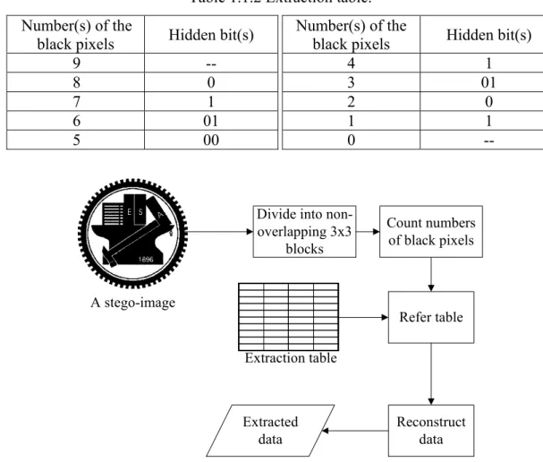
In the proposed data extraction process, Table 1.1.1 is first simplified as an extraction table as shown in Table 1.1.2. It is easy to finish the extraction process. The stego-image is first divided into non-overlapping 3×3 blocks. For each 3×3 block, the number of black pixels in it is computed. And by table lookup, the embedded data bit(s) in the block can be determined. After extracting all embedded data bits, they are converted to obtain the original data.
Table 1.1.2 Extraction table. Number(s) of the
black pixels Hidden bit(s)
9 -- 8 0 7 1 6 01 5 00 Number(s) of the
black pixels Hidden bit(s)
4 1 3 01 2 0 1 1 0 --
Divide into non-overlapping 3x3 blocks Count numbers of black pixels Refer table Reconstruct data Extracted data A stego-image Extraction table
Figure 1.1.3 Flowchart of the proposed extraction process.
1.1.3 Experimental Results
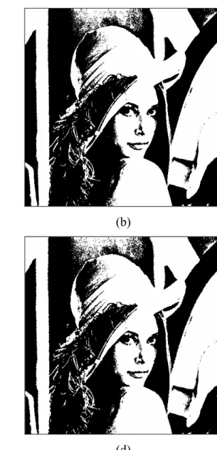
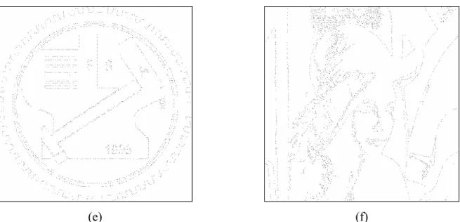
Some experimental results of applying the proposed method are shown here. The secret data α are designed to be K times duplications of the string “1100,” i.e., α = 110011001100…1100. Figures 1.1.4(a)
and (b) show two binary images both with size 512×512. And the stego-images after embedding the secret data are shown in Figures 1.1.4(c) and (d), respectively. And Figures 1.1.4(e) and (f) show their differences in black pixels after embedding the secret data, respectively.
Figures 1.1.5(a) and (b) show two binary document images both with size 512×512. And the stego-images after embedding the secret data are shown in Figures 1.1.5(c) and (d), respectively. And Figures 1.1.5 (e) and (f) show their differences in black pixels after embedding the secret data, respectively. And Table 1.1.3 shows the numbers of the used blocks, the amount of the embedded bits, and the numbers of the difference pixels for the four binary images. An average amount of embedded bits in a block is 1.25~1.30 bits.
1.1.4 Discussions and Summary
In this chapter, we propose a novel data hiding technique for binary images. An embedding table is created in our proposed method. With the help of the table, we can understand what kinds of combinations of bits should be embedded in a block. Our method can embed up to two bits in a 3×3 image block, by changing at most just one bit in a block. Besides, the image quality will be also considered in our method. In order to keep the image quality, each pixel that needs to be flipped must be located in the image boundary. The reason is that it is imperceptible for the human visual system to flip pixels in the image boundary to be black or white one. Therefore, by our method, not only more data can be embedded in a binary image, but also the quality of the stego-image will be not bad.
(a) (b)
(c) (d)
Figure 1.1.4 Input binary images, output stego-images with secret data, and the differences. (a) Binary image “NCTU”. (b) Binary image “Lena”. (c) and (d) Stego-images after embedding secret data, respectively. (e) and (f) The difference pixels after embedding secret data, respectively.
(e) (f)
Figure 1.1.4 Input binary images, output stego-images with secret data, and the differences. (a) Binary image “NCTU”. (b) Binary image “Lena”. (c) and (d) Stego-images after embedding secret data, respectively. (e) and (f) The difference pixels after embedding secret data, respectively (continued).
(a) (b)
Figure 1.1.5 Input binary document images, output stego-images with secret data, and the differences. (a) Chinese binary document images. (b) English binary document images. (c) and (d) Stego-images after embedding secret data, respectively. (e) and (f) The difference pixels after embedding secret data, respectively.
(c) (d)
(e) (f)
Figure 1.1.5 Input binary document images, output stego-images with secret data, and the differences. (a) Chinese binary document images. (b) English binary document images. (c) and (d) Stego-images after embedding secret data, respectively. (e) and (f) The difference pixels after embedding secret data, respectively (continued).
Table 1.1.3 The statistics about the numbers of used blocks, embedded bits, and difference pixels for stego-images of Figs. 1.1.4 and 1.1.5 after embedding the secret data.
NCTU Lena Chinese English
Used blocks 3243 4489 6755 6472
Embedded bits 4181 5572 8842 8364
1.2 A New Image Authentication Technique for
Binary Images
In this chapter, the proposed new method for binary image authentication is presented. By rearranging all the pixels of each block in a binary image, authentication signals represented by the pixels’ locations can be embedded in the image. Image authentication can be achieved by checking the rearranged locations of all the pixels in each block of a given image in suspicion.
The remainder of this section is organized as follows. In Section 1.2.1, an introduction is given first. In Section 1.2.2, the proposed authentication method is described. In Section 1.2.3, some experimental results are given to show the feasibility of the proposed approach. Finally, in Section 1.2.4 some discussions and a summary are made.
1.2.1 Introduction
Because image transmission is a major activity in today’s communication and digital images can be modified easily, it is necessary to design an effective algorithm for image authentication. However, in a binary image there are only two types of pixels, black and white, with values 0 and 255, respectively, and so if the values of the image pixels are flipped arbitrarily, visible artifacts in the image will be created. Therefore, authentication of binary images is a more challenging work than that of other types of images.
In order to verify the fidelity of a binary image, authentication signals need to be embedded in the image. It is hoped that such signals may also be used to check the integrity of each image block. The proposed method meets these two purposes. It takes all the pixels of a properly-selected 3×3 block in each 9×9 block to compute an authentication signal. Such authentication signals can be used to conduct the authentication work for a given image without using other information.
In this section, the proposed method to embed authentication signals into a binary image and to authenticate the resulting image is introduced. The idea of inverse halftoning is employed in our method. The halftone technique was proposed to convert grayscale images into binary ones and the inverse halftoning process aims to recover grayscale images from binary halftone images. In the modified inverse halftoning technique proposed in this study for use in authentication signal generation, each 3×3 block of a given binary image is assigned a gray value.
1.2.2.1 Authentication Signal Generation and Embedding
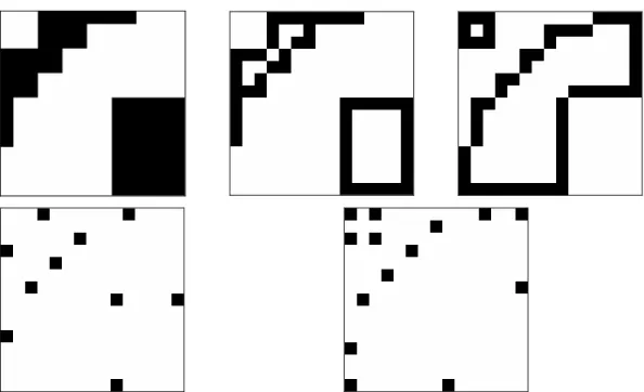
To generate authentication signals for a binary image, the image is first divided into non-overlapping 9×9 blocks. Then, each 9×9 block is divided further into nine non-overlapping 3×3 blocks. Figure 1.2.1 shows an example of a 9×9 block and its nine 3×3 blocks.
(a) (b)
Figure 1.2.1 An example of 9×9 image blocks. (a) A 9×9 block. (b) Each 3×3 block in the 9×9 block.
A. Assigning Gray Values to 3×3 Blocks
In the proposed modified inverse halftoning technique, each 3×3 binary image block B is assigned a gray value G by the following the reduced halftone gray function proposed in this study:
G = ⎣(9 − N) × 255 / 9⎦, (1.2.1)
where N is the number of black pixels in B, and ⎣•⎦ means the integer floor function. The reduced halftone gray function maps the range of gray values [0 255] into 9 discrete gray levels. That is, for an input N, B is assigned a gray value G which is one of the nine values 0, 28, 57, …, 255. For example, if N is 0, the assigned gray value is 255. If N is 6, then the assigned value is 85. And if N is 9, the assigned value is 0. Therefore, in each 9×9 block with nine 3×3 blocks, nine gray values will be assigned. Such
assigned gray values will be called reduced halftone gray values, and abbreviated as RHG values, where the word reduced is used to indicate that only nine discrete gray values instead of the usual 256 ones are generated here from the gray scale.
B. Choice of Rearrangeable Block
In order to control the quality of the image resulting from authentication signal embedding, we should select 3×3 image blocks carefully to embed the signals. Each block selected for this purpose is called a rearrangeable block in this study. The reason for using this term will be obvious later. For each 9×9 block, if it is neither entirely black nor entirely white, two candidate 3×3 blocks for signal embedding are picked out within it. One block is that with its RHG value Gs being the smallest but not 0,
and the other that with its RHG value Gl being the largest but not 255. The reason to select them is
explained subsequently. First, a larger RHG value means that the black pixels in the block are fewer, and a smaller RHG value means the reverse. Taking the latter case as an example, it means that the white pixels in the block are fewer. So it will cause less distortion to rearrange the positions of these white pixels than to rearrange those of the black ones. Similar reasoning applies to the former case. The desired rearrangeable block is chosen from the two candidate blocks in this study. Let ws be the number
of white pixels in the block Bs whose RHG value is Gs and bl be the number of black pixels in the block
Bl whose RHG value is Gl. If ws is larger than or equal to bl, then according to the previous discussion Bs
is taken as the rearrangeable block in the proposed method; otherwise, Bl is taken as the rearrangeable
block. We call this way of selecting a rearrangeable block in a 9×9 block a rearrangeable block selection process in the sequel.
C. Calculation of Standard Deviation
For each 9×9 block, a standard deviation σ of the RHG values of the eight 3×3 blocks other than the rearrangeable block is calculated. And a standard deviation level L is computed according to the following rule:
L = n, if (n × 128 / 9) ≥ σ ≥ [(n − 1) × 128 / 9]. (1.2.2)
Because in the gray value range [0 255], the largest integer value of the standard deviation σ is 128, the possible value of σ will fall within the range R = [0, 127]. Therefore, we normalize R into 9 levels in
and when σ = 80, L = n =6.
D. Rearrangement of Pixels
For the rearrangeable 3×3 block B in each 9×9 block, let N be the number of black pixels in this block. We consider two cases in the following.
(a). Case 1:
If N ≤ 4, it means the number of black pixels in B is fewer than the number of white ones. So, it is faster and also causes less distortion to rearrange the locations of the N black pixels in B than to do so for the (9 − N) white ones. Therefore, we will assign N new locations to the N black pixels, respectively. We employ the value N and the standard deviation level L to produce a rearrangement rule for this purpose as follows:
(
L N mod C)
mod 9Pib = × i for all i ≤ N and N ≤ 4, (1.2.3)
where denotes the index of the new location of the ith black pixel in B and C is a constant pre-selected in such a way that each value of is distinct. The indexes of the original locations of a 3×3 block is shown in Figure 1.2.2. The value of C is chosen to be 11 according to our experimental experience in this study. As a summary, the essence of the proposed binary image authentication method is that all the indexes specified by are regarded as authentication signals.
b i P b i P b i P 8 7 6 5 4 3 2 1 0 8 7 6 5 4 3 2 1 0
Figure 1.2.2 Indices of a 3×3 block.
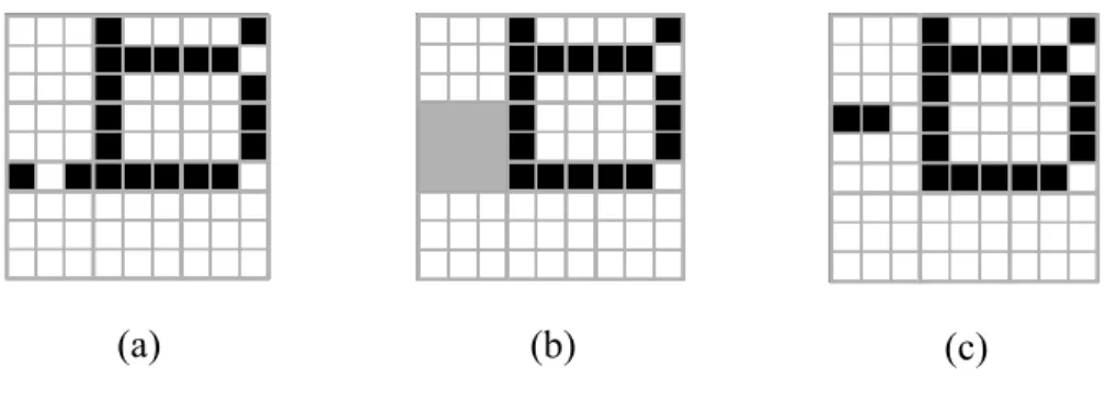
For example, Figure 1.2.3(a) is a 9×9 block and Figure 1.2.3(b) shows the rearrangeable 3×3 block, which is the one in shadow, of a 9×9 block. According to the aforementioned steps, N is 2 and L is 5. By (1.2.3), we can compute to be 1 and 0. That is, the two pixel positions with indexes, 0 and 1, are filled with black pixels according to the proposed rearrangement rule. The other positions will be filled with white pixels. Figure 1.2.3(c) is the resulting 9×9 block after embedding the authentication signals in this way.
b
(a) (b) (c)
Figure 1.2.3 An example. (a) A 9×9 block. (b) The rearrangeable 3×3 block (in shadow) of the 9×9 block. (c) The 9×9 block resulting from embedding authentication signals.
(b). Case 2:
If N ≥ 5, it means that the number of black pixels in B is larger than the number of white ones, which is (9 − N). So, it is fasterand causes less distortion to rearrange the locations of the (9 − N) white pixels in B than to rearrange those of the N black ones. That is, we will assign (9 − N) new locations to the (9 − N) white pixels, respectively. We again employ the values of N and L to produce another rearrangement rule as follows:
(
L N mod C)
mod 9Piw = × i for all i ≤ (9 − N) and N ≥ 5, (1.2.4)
where denotes the index of the new location of the ith white pixel in B and C is a constant pre-selected to be 11 in a way as mentioned previously. Similarly all are regarded as authentication signals in this study.
w i P w i P
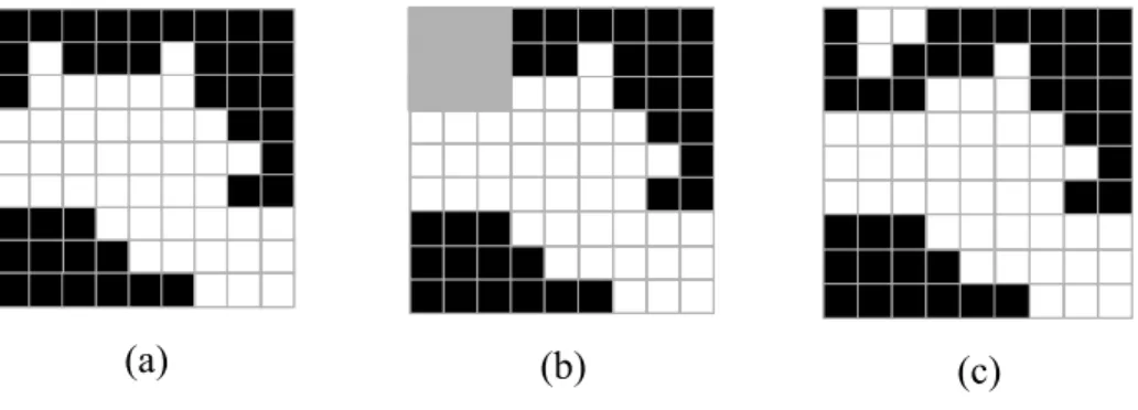
For example, Figure 1.2.4(a) is a 9×9 block and Figure 1.2.4(b) shows its rearrangeable 3×3 block in shadow. According to the aforementioned steps, N is 6 and L is 8. By (1.2.4), we can compute , , and to be 2, 2, and 1, respectively. That is, the three pixels at positions, 1, 2, and 4, are filled with white pixels according to the rearrangement rule. The other positions are filled with black pixels. Figure 1.2.4(c) shows the resulting 9×9 block after embedding the authentication signals in this way.
w
(a) (b) (c)
Figure 1.2.4 Another example. (a) A 9×9 block. (b) The rearrangeable 3×3 block (in shadow) of the 9×9 block. (c) The 9×9 block after embedding authentication signals.
Based on the idea of the inverse halftoning, it is noted the RHG value of the rearrangeable 3×3 block, after the above pixel rearrangement, will still be the same as before because the change is just a permutation of the pixels’ positions and not the number of the black pixels or white pixels.
E. Detailed Algorithm
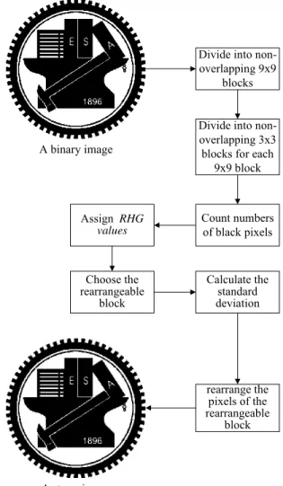
The input to the proposed authentication signal embedding process is a binary image I. The output is a stego-image S. The algorithm for the process is as follows. Figure 1.2.5 shows a flowchart for the algorithm.
Step .1 Divide I into non-overlapping 9×9 blocks.
Step .2 Divide each 9×9 image block further into non-overlapping 3×3 blocks.
Step .3 For each 3×3 image block, count the number N of the black pixels in it and assign it an RHG value Gi by the reduced halftone gray function described by (1.2.1).
Step .4 For each 9×9 image block D, perform the following operations.
4.1. Find the rearrangeable block B in D using the RNG values of all the blocks in D according to the aforementioned rearrangeable block selection process.
4.2. For each of the remaining eight 3×3 blocks in D, calculate its standard deviation σ and get the standard deviation level L according to (1.2.2).
4.3. For the 3×3 rearrangeable block B, rearrange all pixels of B according to (1.2.3) and (1.2.4).
1.2.2.2 Image Authentication Process
In the authentication signal embedding process, the locations of all pixels of the rearrangeable 3×3 block are taken as authentication signals. So, we can judge an image in suspicion as being tampered with or not by checking the locations of all pixels of the 3×3 rearrangeable block according to the rearrangement rule described previously.
A binary image
Divide into non-overlapping 9x9
blocks
Divide into non-overlapping 3x3 blocks for each
9x9 block Count numbers of black pixels Assign RHG values Choose the rearrangeable block Calculate the standard deviation rearrange the pixels of the rearrangeable block A stego-image
Figure 1.2.5 Flowchart of authentication signal embedding process.
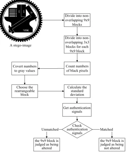
The proposed image authentication process is essentially similar to the proposed authentication signal embedding process but in a reverse order. A suspicious image is first divided into non-overlapping 9×9 blocks. Then, each 9×9 block is divided further into nine non-overlapping 3×3
3×3 block in it is selected. The standard deviation σ and the level L of σ of each of the remaining eight 3×3 blocks are then computed. By the rearrangement rules (1.2.3) and (1.2.4) with N and L as inputs, authentication signals or can be obtained. By checking the permutation of all the pixels of the rearrangeable block, if the computed indexes (or ) are the same as the locations of all the black (or white) pixels of the rearrangeable block, the 9×9 block is judged as not being altered; otherwise, tampered with. In the output images of our experiments, blocks judged as being tampered with are marked with red color.
b i P Piw b i P Piw A. Detailed Algorithm
The proposed image authentication algorithm can be expressed as an algorithm as follows. The input is a stego-image S. The output is an authentication image A. Figure 1.2.6 illustrates the process.
Step .1 Divide S into non-overlapping 9×9 blocks.
Step .2 For each 9×9 image block, divide it further into non-overlapping 3×3 blocks.
Step .3 For each 3×3 image block, counter the number Ni of black pixels in it and assign it an RHG value Gi by reduced halftone gray function specified by (1.2.1).
Step .4 For each 9×9 image block D, perform the following operations.
4.1 Find the 3×3 rearrangeable block B of D according to the aforementioned rearrangeable block selection process.
4.2 For each of the remaining eight 3×3 blocks in D, calculate its standard deviation σ and get the corresponding standard deviation level L according to (1.2.2).
4.3 For the 3×3 rearrangeable block B with N black pixels, perform the following operations. 4.3.a If N ≤ 4, calculate authentication signals by (1.2.3) for i =1, 2, …, N. Let the
index of ith black pixel be denoted as for i =1, 2, …, N. For all i, if ≠ , regard the 9×9 image block as being tampered with and mark it red.
b i P b i p Pib pib
4.3.b If N ≥ 5, calculate authentication signals by (1.2.4) for i =1, 2, …, (9 − N). Let the index of ith white pixel be denoted as for i =1, 2, …, (9 − N). For all i, if ≠ , regard the 9×9 image block as being tampered with and mark it red. w i P w i p w i P piw
4.4 Take the final result as the desired stego-image S.
A stego-image
Divide into non-overlapping 9x9
blocks Divide into non-overlapping 3x3 blocks for each
9x9 block Count numbers of black pixels Covert numbers to gray values Choose the rearrangeable block Calculate the standard deviation Check authentication signals the 9x9 block is judged as being not altered the 9x9 block is judged as being altered Matched Unmatched Get authentication signals
Figure 1.2.6 Flowchart of proposed image authentication process.
1.2.2.3 Applications
For binary images, we can apply the proposed image authentication method to check whether a binary image is tampered with or not. But this is just one application of the proposed method described previously. Another application of the method is described in this section.
In Section 1.1, we have introduced a data hiding method for binary images. In this data hiding method, we take the number of black pixels in each 3×3 binary image block as a kind of combination of bits. Because the proposed method for embedding authentication signals described in the last section
authenticate the hidden data. This application will not destroy the hidden data. That is, after implementing image authentication method, we can extract correctly the hidden data.
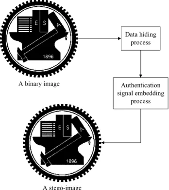
More specifically, if a person, say A, wants to send some secret data to another person, say B. First, A can implement the data hiding method proposed previously to embed the secret data in a binary image, yielding a stego-image T. Next, A can apply the image authentication method proposed in this chapter to embed authentication signals in T and produce another stego-image F. Finally, A sends F to B.
Before extracting data from F, B can employ the image authentication process to verify the integrity of F. If the result of image authentication says that the image F is not tampered with, then B can proceed to extract the hidden data correctly. Otherwise, B, knowing that the received image F has been altered, can abandon it and ask A to send the secret data hidden in a similar way again. Figure 1.2.7 shows a flowchart of this application.
A binary image Data hiding process Authentication signal embedding process A stego-image
Figure 1.2.7 Flowchart of application.
1.2.3 Experimental Results
Some experimental results of applying the proposed method are shown here. Figures 1.2.8 (a) and (b) show two binary images both with size 512×512. And the stego-images resulting from embedding the authentication signals are shown in Figures 1.2.8 (c) and (d), respectively. And Figures 1.2.8 (e) and
(f) show their differences in black pixels after embedding authentication signals, respectively.
Figures 1.2.9 (a) and (b) show two binary document images both with size 512×512. And the stego-images resulting from embedding the authentication signals are shown in Figures 1.2.9 (c) and (d), respectively. And Figures 1.2.9 (e) and (f) show their differences in black pixels after embedding authentication signals, respectively.
Four tampered and cropped images are shown in Figures 1.2.10 (a) through (d). And Figures 1.2.10 (e), (f), (g), and (h) show the respective authentication results. The red parts indicated the detected tampered areas.
Figures 1.2.11 (a) and (b) show two binary images both with size 512×512. And the stego-images resulting from embedding the secret data and the authentication signals are shown in Figures 1.2.11 (c) and (d), respectively. And Figures 1.2.11 (e) and (f) show their differences in black pixels after embedding the secret data and the authentication signals, respectively.
Figures1..2.12 (a) and (b) show two binary document images both with size 512×512. And the
stego-images after embedding secret data and authentication signals are shown in Figures 1.2.12 (c) and (d), respectively. And Figures 1.2.12(e) and (f) show their difference in black pixels after embedding secret data and authentication signals, respectively.
(a) (b)
Figure 1.2.8 Input binary images, output stego-images with authentication signals, and the differences. (a) Binary image “NCTU”. (b) Binary image “Lena”. (c) and (d) Stego-images after embedding
(c) (d)
(e) (f)
Figure 1.2.8 Input binary images, output stego-images with authentication signals, and the differences. (a) Binary image “NCTU”. (b) Binary image “Lena”. (c) and (d) Stego-images after embedding authentication signals, respectively. (e) and (f) The difference pixels after embedding authentication signals, respectively (continued).
(a) (b)
(c) (d)
Figure 1.2.9 Input binary document images, output stego-images with authentication signals, and the differences. (a) Chinese binary document images. (b) English binary document images. (c) and (d) Stego-images after embedding authentication signals, respectively. (e) and (f) The difference pixels after embedding authentication signals, respectively.
(e) (f)
Figure 1.2.9 Input binary document images, output stego-images with authentication signals, and the differences. (a) Chinese binary document images. (b) English binary document images. (c) and (d) Stego-images after embedding authentication signals, respectively. (e) and (f) The difference pixels after embedding authentication signals, respectively (continued).
(a) (b)
Figure 1.2.10 Some tampered images and authentication results. (a) – (c) and (d) Tampered images. (e) – (g) and (h) authentication results, respectively.
(c) (d)
(e) (f)
Figure 1.2.10 Some tampered images and authentication results. (a) – (c) and (d) Tampered images. (e) – (g) and (h) authentication results, respectively (continued).
(g) (h)
Figure 1.2.10 Some tampered images and authentication results. (a) – (c) and (d) Tampered images. (e) – (g) and (h) authentication results, respectively (continued).
(a) (b)
Figure 1.2.11 Input binary images, output stego-images with secret data and authentication signals, and the differences. (a) Binary image “NCTU”. (b) Binary image “Lena”. (c) and (d) Stego-images after embedding secret data and authentication signals, respectively. (e) and (f) The difference pixels after embedding secret data and authentication signals, respectively.
(c) (d)
(e) (f)
Figure 1.2.11 Input binary images, output stego-images with secret data and authentication signals, and the differences. (a) Binary image “NCTU”. (b) Binary image “Lena”. (c) and (d) Stego-images after embedding secret data and authentication signals, respectively. (e) and (f) The difference pixels after embedding secret data and authentication signals, respectively (continued).
(a) (b)
(c) (d)
Figure 1.2.12 Input binary document images, output stego-images with secret data and authentication signals, and the differences. (a) Chinese binary document images. (b) English binary document images. (c) and (d) Stego-images after embedding secret data and authentication signals, respectively. (d) and (e) The different pixels after embedding secret data and authentication signals, respectively.
(e) (f)
Figure 1.2.12 Input binary document images, output stego-images with secret data and authentication signals, and the differences. (a) Chinese binary document images. (b) English binary document images. (c) and (d) Stego-images after embedding secret data and authentication signals, respectively. (d) and (e) The different pixels after embedding secret data and authentication signals, respectively (continued).
1.2.4 Discussions and Summary
In this chapter, we have presented a novel authentication scheme to embed authentication signals in binary images. We change the positions of white or black pixels in so-called rearrangeable blocks to obtain and embed authentication signals. That is, authentication signals are taken as the permutation of all the pixels of the rearrangeable block in each 9×9 image block. Because the authentication signal of each 9×9 image block contains certain relationship contributed by the standard deviation of the RHG values of other eight 3×3 blocks in the 9×9 block, if somebody wants to tamper with the stego-image, we can get a different standard deviation value and different authentication signals in each 9×9 block. The result is that the permutation of the rearrangeable 3×3 block in the tampered image may be not the same as the calculated authentication signals. Therefore, by checking the permutation, the tampered areas can be detected and located.
However, in the proposed authentication signal embedding methods, we do not deal with entirely black or entirely white blocks. Therefore, if somebody replaces part of a stego-image with an entirely black or entirely white region, the tampered region cannot be located. In future works, it may be tried to solve this problem.
Chapter 2
Development of Data Hiding Techniques and
Applications for Binary Document Images
2.1
Hiding Authenticable General Digital
Information behind Binary Document
Images with Reduced Distortion
2.1.1 Abstract
Binary document images are the images scanned or digitalized from printing or manuscripts. The significant feature of binary document images is that they have white blocks with large areas. A new approach to information hiding in binary document images with the capabilities of authenticating hidden digital data and reducing distortion effects in resulting stego-images due to data embedding is proposed. The information, which may be hidden, is general in type, and so may be of any form of secret bit streams. Based on a new feature called surrounding edge count for measuring the structural randomness in an image block, pixel embeddability is defined from the viewpoint of reducing the distortion caused by embedded pixel values. Accordingly, embeddable image pixels suitable for hiding secret data are selected. Furthermore, an error-correcting scheme is used both for extracted data authentication and embedding distortion reduction. Finally, to increase the security of embedded data, a secret key and a random number generator are also employed to randomize the locations of selected cover image pixels into which secret data are embedded. Experimental results show the feasibility of the approach for real applications.
2.1.2 Introduction
Information hiding behind digital images has many applications, including covert communication, copyright protection, annotation association, etc. However, it is generally difficult to hide information behind binary document images. There are at least three reasons for this problem. First, embedding data in a binary cover image will cause obvious image content changes because of the binary (black and white) nature of the image. This indicates that reduction of image distortion due to data embedding (called embedding distortion in the sequel) should be taken as a major consideration in designing data hiding algorithms. Next, binary document images are more fragile to disturbances or attacks like channel noise or image operations. Such a characteristic makes authentication of recovered hidden information a required work. Finally, with the widespread use of color images, binary document images today are used mainly for conveying text or graphic based document images in which color is not important information, and so the semantics of binary image contents are very vulnerable to pixel value changes due to data hiding. This means that a more careful selection of image pixels for data hiding is required; pixel value changes leading to obvious destruction of image contents should be avoided. In this paper, we propose an information hiding method which takes the above three requirements into consideration. Moreover, the digital information that can be hidden by the method is general in type, which we assume to be secret bit streams in the sequel.
There were only a few studies in the past about information hiding behind binary document images, possibly due to the difficulty mentioned above. Wu, et al. [1] embedded bits in image blocks selected by pattern matching. The method can be used both for data hiding and for image authentication. Tseng, et al. [2] changed pixel values in image blocks and mapped block contents into the data to be hidden. In [3, 4], word or line spaces in textural document images are utilized to embed watermarks for copyright protection. In [5, 6], secret information is embedded into dithered images by manipulating dithering patterns. And Koch and Zhao [7] embedded a bit 0 or 1 in a block by enforcing the ratio of the number of black pixels in the block to that of white ones to be larger or smaller than the value 1, respectively. The method proposed in this study may be used for data hiding as well as for data authentication.
More specifically, in the proposed approach we define a measure of pixel embeddability by which we can select suitable cover image pixels for embedding secret data. This measure is defined in such a way that embedding distortion can be reduced, and that pixels selected for data embedding can be
identified correctly later for secret recovery. We also employ an error-correcting scheme to encode secret stream before secret embedding for the purposes of authenticating the extracted secret stream as well as reducing embedding distortion in a more global way. At last, we propose the use of a secret key as well as a random number generator to randomize the locations of the selected pixels for data embedding. This enhances the safety of the hidden data from being attacked or accessed illicitly. Based on these measures of distortion reduction and safety protection, processes for secret hiding and recovering are proposed. Some experimental results are also included to show the effectiveness the proposed method.
In the remainder of this section, we first describe the proposed processes of secret hiding and recovering in Section II, followed by the descriptions of the details of the involved measures for distortion reduction and safety protection in Section III. Some experimental results are given in Section IV, followed by a conclusion in Section V.
2.1.2.1 Proposed Secret Embedding and Recovering Processes
In the proposed approach, we hide a given secret bit stream behind a cover binary image in a random fashion controlled by a secret key and a random number generator. The proposed secret hiding and recovering processes are described in this section. Only basic ideas are included; the details of the involved terms and techniques will be explained in the next section. In the sequel, by embedding a value v into a pixel p, we mean to replace the value of p with v; and by extracting a value v from p, we mean to take v to be the value of p.Algorithm 1. Secret hiding process.
Input: a secret bit stream S, a cover image I, a secret key K, a random number generator g, and three
pre-selected positive integer numbers m, n, and t.
Output: a stego-image I’ in which S is embedded. Steps:
1. Take sequentially m bits of S and encode the bits using a t-error-correcting scheme to form an n-bit substream s.
2. Create a set C of n-bit streams from s by changing at most t bits in s in all possible ways. 3. Select an ordered sequence E of n embeddable pixels in I randomly using g with K as the seed. 4. Select from C a substream sopt, which causes minimum distortion, when embedded into E (as
6. Repeat Steps 1 through 5 until all bits in S are processed.
For convenience, in the sequel each pixel selected to be included in E in Step 3 above is said to have been visited. On the other hand, the proposed secret recovering process (including secret bit stream extraction and authentication) is described as follows.
Algorithm 2. Secret recovering process.
Input: a stego-image I’ presumably including a secret bit stream S; and the secret key K, the
random number generator g, as well as the positive integer numbers m, n, and t all used in Algorithm 1.
Output: the secret bit stream S or the report of failure to recover the secret. Steps:
1. Select an ordered sequence E of n embeddable pixels in I’ using g with K as the seed. 2. Extract a bit b’ from each pixel p in E with value v by setting b’ = v, and compose all the n
extracted bits sequentially to form a bit stream s’.
3. Decode s’ by the t-error-correcting scheme used in Algorithm 1 to recover an m-bit secret stream s”. If more than t errors are found in s’ during the decoding process, decide the bits of s” to be unauthentic, yield a report of failure to recover the secret, and exit; otherwise, take s”as part of the desired secret bit stream S.
4. Repeat the above steps to extract other m-bit substreams to compose the remaining part of S until done.
The ordered sequence E of pixels selected in Step 1 above presumably should be identical to that yielded in Step 3 of Algorithm 1 to ensure that the secret bit stream can be extracted correctly. For this to be true, in addition to requiring the use of the same random number generator g and the same secret key K in the two processes as already done, an extra condition is that the embeddability of the selected pixels must be preserved after the secret hiding process, and not be changed before the secret recovering process. We satisfy this condition by proposing a proper definition of pixel embeddability, as described in the next section.
2.1.2.2 Proposed Pixel Embeddability And Distortion
Reduction Measures
In the above secret hiding process, we select embeddable pixels from a cover image to embed secret bits. We define pixel embeddability in this section from the viewpoint of reducing embedding distortion. First, we propose a new type of feature, called surrounding edge count and abbreviated as SEC. Let B be a 3×3 block in a cover image I with pixel p being its center and pixels p1, p2, …, and p8 being the eight surrounding neighbors of p in B. The SEC of p, denoted as SECp, is defined as the number of existing edges between p and its eight neighbors in B. Since the cover image I is binary, the existence of an edge between p with value v and one of its neighbors, say pi with value vi, means that |vi − v| = 1, and the reverse situation means that |vi − v| = 0. This in turn means that SECp may be computed by
The SEC value of p is a measure of the structural randomness in the block from the centralized viewpoint of p. By definition, the SEC value of a fully black or white block is 0 (no edge exists), that of a block filled with a checker pattern is 4 (four edges exist), and that of a white (or black) pixel surrounded by eight black (or white) neighbors is 8 (eight edges exist).
Next, we define a measure of distortion resulting from complementing the value v of p by: ∆SECp = |SECp − SECp ’|
where SECp and SECp ’ denote the SEC values before and after the complementation operation, respectively. It is not difficult to figure out that the above measure of distortion is just the amount of the resulting change of the edge numbers in B. As an example, if the central pixel p of a fully black block is changed to be a white pixel, the above distortion value ∆SECp will have the largest possible value 8, which cannot be endured because the new white central pixel is too contrastive to its eight black neighbors.
Finally, we define a pixel p in a block to be embeddable (i.e., suitable for embedding a bit value) if the following two conditions are satisfied:
(a) ∆SECp < Td; and
(b) p and its eight neighbors in B have not been visited yet, where Td is a pre-selected threshold value. Condition (a) above restricts the distortion introduced by the complementation of p’s value to be sufficiently small, so that the resulting image quality will not be affected too much. And Condition (b)