國 立 交 通 大 學
機 械 工 程 學 系
博 士 論 文
脊突間裝置(Coflex and Coflex-F)在非融合與融合手術
的生物力學分析
Biomechanical Analysis of Interspinous Process Device (
Coflex and
Coflex-F
) in Non-Fusion and Fusion Surgery
研 究 生:羅正展
指導教授:洪景華 教授
脊突間裝置(Coflex and Coflex-F)在非融合與融合手術
的生物力學分析
Biomechanical Analysis of Interspinous Process Device
(Coflex and
Coflex-F)
in Non-Fusion and Fusion Surgery
研 究 生: 羅正展
Student: Cheng-Chan Lo
指導教授: 洪景華
Advisor: Chinghua Hung
國 立 交 通 大 學
機械工程學系
博 士 論 文
A Thesis
Submitted to Department of Mechanical Engineering College of Engineering
National Chiao Tung University in Partial Fulfillment of the Requirements
for the Degree of Doctor of Philosophy
in
Mechanical Engineering January 2011
Hsinchu, Taiwan, Republic of China
i
脊突間裝置(Coflex and Coflex-F)在非融合與融合手術的
生物力學分析
研究生:羅正展 指導教授:洪景華 教授國立交通大學機械工程學系
摘 要
在脊椎病變中,椎間盤初期退化常造成神經壓迫,形成腰椎狹窄症(Stenosis)。為改 善神經壓迫而施予減壓手術,傳統的減壓手術會造成其他後續病發症,因此近年發展屬 於非融合手術(Non-Fusion)的脊突間裝置 Coflex 希望能減少此類問題。椎間盤退化程度 嚴重時會造成椎體不穩定,因此需要使用融合手術(Fusion),新型的脊突間裝置 Coflex-F 可以改善傳統椎弓螺釘在手術過程的風險。 本研究利用有限元素軟體建構出五節的腰椎模型。第一階段,將脊突間裝置 Coflex 與 Coflex-F 分別放置腰椎第三與第四椎節之間,探討在非融合手術時的影響。第二階段, 則將 TLIF 和 ALIF 椎間融合術搭配 Coflex-F 於腰椎第三與第四椎節之間,探討融合手 術的效果。第三階段,則將 TLIF 椎間融合術搭配 Coflex-F 於腰椎第三與第四椎節之間, 探討是否可以使用在微創的融合手術。以上研究的邊界條件則都施加 400N 的跟隨負荷 (Follower load),並使用混合控制方式(Hybrid test method)針對腰椎生理學動作進行分析 比較。 第一階段結果發現,Coflex 在手術端可以穩定後彎(角度減少 70%)、側彎(角度減少 8%)與扭轉(角度減少 4.3%),並且保留了前彎的活動(角度增加 8%);對於鄰近端,後彎 時有明顯的影響(角度增加 20~24%)。然而 Coflex-F 在手術端可以穩定所有動作,特別 是前彎動作(角度減少 52%);在鄰近端,前彎(角度增加 17~18%)與後彎(角度增加 20~24%) 有明顯的影響。第二階段結果發現,ALIF 融合術搭配 Coflex-F 的穩定效果較好。第三 階段結果發現,TLIF 融合術搭配 Coflex-F 無法提供較好的穩定效果。 關鍵字:融合、非融合、脊突間裝置、椎間融合術、混合控制、有限元素分析Biomechanical Analysis of Interspinous Process Device
(Coflex and Coflex-F) in Non-Fusion and Fusion Surgery
Student: Cheng-Chan Lo Advisor: Prof. Chinghua Hung
Department of Mechanical Engineering National Chiao Tung University
ABSTRACT
In current society, degenerative disc disease is a very common situation. It can cause nerve root compression, lumbar spinal stenosis, and lumbar instability. In order to relief patients’ symptom, decompression and spinal fusion surgery were common practices by surgeons. In recent years, the concept of interspinous process Coflex device of non-fusion surgery is emerging to improve the complication of decompression surgery. The Coflex-F device is a minimally invasive lumbar fusion device that provides significant segmental stability with all the advantages of an interspinous implant. It can alternative to traditions pedicle screw fixation as an adjunct to spinal fusion.
This study was divided into three researches with purposes to investigate the biomechanical behavior between the Coflex and Coflex-F devices using finite element model of the L1-L5 lumbar spine. The first research was to investigate the biomechanical differences between the Coflex and Coflex-F implanted into the L3-L4 segment in non-fusion surgery. The second was to investigate the biomechanical characteristics of TLIF and ALIF spinal fusion combined with Coflex-F and with pedicle screw fixation implanted into the L3-L4 segment in fusion surgery. The third was to investigate the biomechanical characteristics of TLIF combined with Coflex-F and with unilateral pedicle screw fixation and translaminar
iii
facet screw fixation implanted into the L3-L4 segment in minimally invasive lumbar fusion. A 400 N follower load and a 10 N-m moment were applied to the intact model to mimic physiological motions. The other implanted models to be compared with the intact model were also subjected to 400 N follower load and moments that produced overall motions equal to those of the above intact model (i.e. the hybrid test method).
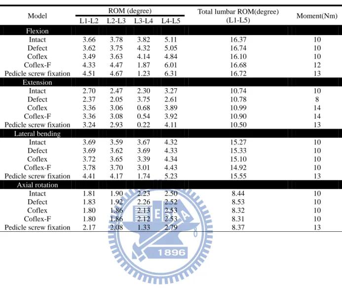
The result of the first research showed that, the Coflex implantation can provide stability in extension (ROM decreased 70%), lateral bending (ROM decreased 8%), and axial rotation (ROM decreased 4.3 %) at the surgical segment, and retain flexible in flexion (ROM increased 8%). It had no influence at adjacent segments except during extension (ROM increased 20~24%). The Coflex device can restraint extension motion, and provide more space for foramen and spinal canal. Therefore, The Coflex device may improve or relieve the stenosis. In addition, the Coflex-F implantation can provide stability in all motions, especially in flexion (ROM decreased 52%). It had influence at adjacent segments during flexion (ROM increased 17~18%) and extension (ROM increased 20~24%). Therefore, the Coflex-F device can be used to treat stenosis combined with mild degenerative disc disease.
The result of the second research showed that, the ALIF combined with Coflex-F can provide more stability. The result of the third research showed that, the TLIF combined with Coflex-F cannot provide sufficient stability.
Keywords: Fusion, Non-Fusion, Interspinous Process Device, Interbody Fusion Surgery, Hybrid Test Method, Finite Element Analysis
誌 謝
首先要衷心地感謝指導教授洪景華老師,願意耗費許多時間教導學生,使學生遭遇 研究瓶頸時,不僅能迎刃而解,且能適時給予信心與鼓勵,引導學生培養獨立研究的態 度與創新構想的思維,讓學生盡情的發揮。 特別感謝國泰醫院骨科蔡凱宙醫師,不但在研究上提供了專業智識與寶貴建議,也 時常的照顧和提醒我,有如親兄弟的大哥。 感謝趙振綱教授、廖建忠博士、陳振昇教授、楊秉祥教授、蔡凱宙醫師在百忙之中 挪出時間參加學生口試給於意見,讓學生的論文更加完整。 回首研究所期間,特別感謝實驗室榮崇學長、宇中學長、雅雯學姊、政成學長,在 遇到困難時,適時剖析建議與協助;感謝研究室夥伴煌棊、麒禎、銘傑、嘉偉、培峰、 彥彬、宗駿、理強、黃詠、志嘉、運賢、世璿、俊羿、志傑、聖平、時恆、麒翔、建榮、 忠諭、明輝、立釗、宗錞、筱偉、正一、振傑、雅喬、書麟、馨云、中南、彥佑、致豪、 品帆、呂翔、宜均在學業及生活中的指導與關懷,還有最佳化與齒輪實驗室的學長們, 以及各位機械研究所的同學們,在研究生涯中的陪伴,所建立的深厚友誼與每一句歡笑 將成為美好的回憶。期間,也受到交大機械所許多師長、助教的教導與提攜,同樣致上 最誠摯的謝意。 感謝碩士班教導我的師長劉永生教授、以及大學時期的師長黃社振教授、嚴家銘教 授、王威立教授、何智廷教授、林瑞璋教授長久以來在實質與精神上不斷的給我支持與 鼓勵。 最後,僅以此論文獻給我最敬愛的雙親與家人,感恩他們多年來不辭辛勞的養育、 栽培與無怨無悔的付出。 作者:羅正展 謹誌 中華民國一百年一月v
Table of Contents
摘要(Abstract in Chinese) ... i Abstract ... ii 誌謝(Acknowledgements in Chinese) ... iv Table of Contents ... vList of Tables ... viii
List of Figures ... ix
Chapter 1: Introduction ... 1
1.1. Overview ... 1
1.2. Motivation and objectives ... 1
1.3. Outline ... 4
Chapter 2: Background ... 6
2.1. Spine anatomy and biomechanics ... 6
2.1.1. Vertebral ... 8
2.1.2. Intervertebral disc ... 9
2.1.3. Facet joint ... 10
2.1.4. Spinal ligaments ... 11
2.1.5. Neural foramen ... 12
2.1.6. Spinal cord and nerve roots ... 12
2.2. Spinal pathology and treatments ... 14
2.2.1. Lumbar spinal stenosis ... 14
2.2.2. Conservative therapy ... 18
2.2.3. Decompression ... 18
2.2.4. Non-fusion surgery ... 19
Chapter 3: Materials and methods ... 30
3.1 Coflex and Coflex-F in non-fusion surgery ... 30
3.1.1 FE model of intact lumbar spine (Intact model) ... 30
3.1.2 FE model of Coflex implanted into the L3-L4 segment (Coflex model) ... 38
3.1.3 FE model of Coflex-F implanted into the L3-L4 segment (Coflex-F model) ... 38
3.1.4 FE model of bilateral pedicle screw fixation into the L3-L4 segment (Pedicle screw fixation model) ... 39
3.1.5 Boundary and loading conditions ... 40
(1) Follower load ... 40
(2) Validation of intact lumbar spine model with follower load ... 41
(3) Hybrid test method ... 42
3.2 Coflex-F in fusion surgery ... 46
3.2.1 FE model of TLIF combined with Coflex-F (Coflex-F + TLIF model) ... 46
3.2.2 FE model of ALIF combined with Coflex-F (Coflex-F+ ALIF model) ... 47
3.2.3 FE model of TLIF combined with bilateral pedicle screw fixation (Pedicle screw + TLIF model) ... 48
3.2.4 FE model of ALIF combined with bilateral pedicle screw fixation (Pedicle screw + ALIF model) ... 48
3.2.5 Boundary and loading conditions ... 50
3.3 Coflex-F in minimally invasive fusion surgery ... 52
3.3.1 FE model of TLIF combined with Coflex-F (Coflex-F model) ... 52
3.3.2 FE model of TLIF combined with unilateral pedicle screw fixation with translainar facet screw fixation (UPSF+TFSF model) ... 52
3.3.3 FE model of TLIF combined with bilateral pedicle screw fixation (BPSF model) ... 53
vii
Chapter 4: Results ... 56
4.1 Coflex and Coflex-F in non-fusion surgery ... 56
4.1.1 Range of motion (ROM) ... 56
4.1.2 Maximal von-Mises stress at the disc annulus ... 59
4.1.3 Von-Mises stress distribution at the disc annulus ... 63
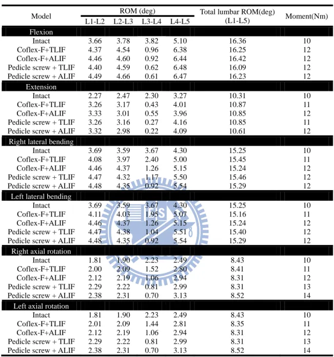
4.2 Coflex-F in fusion surgery ... 69
4.2.1 Range of motion ... 69
4.2.2 Von-Mises stress distribution on the cage-bone interface ... 71
4.2.3 Von-Mises stress distribution for the Coflex-F and the pedicle screw ... 74
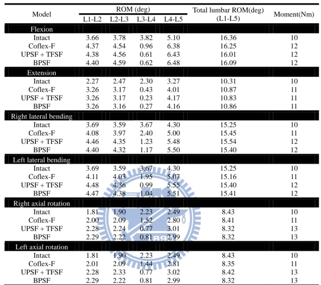
4.3 Coflex-F in minimally invasive fusion surgery ... 75
4.3.1 Range of motion ... 75
Chapter 5: Discussion ... 79
5.1 Coflex and Coflex-F in non-fusion surgery ... 79
5.2 Coflex-F in fusion surgery ... 81
5.3 Coflex-F in minimally invasive fusion surgery ... 83
5.4 limitation ... 84
Chapter 6: Conclusion and future work ... 86
6.1 Conclusion ... 86
6.2 Future work ... 86
References ... 89
Vita... 98
List of Tables
Table 3.1: Material properties used in the FE model ... 35 Table 3.2: Intervertebral range of motion and applied moment among the intact, defect,
and implantation models under the hybrid test method ... 45 Table 3.3: Intervertebral range of motion and applied moment among various surgical
models under the hybrid test method ... 51 Table 3.4: Intervertebral range of motion and applied moment among various surgical
ix
List of Figures
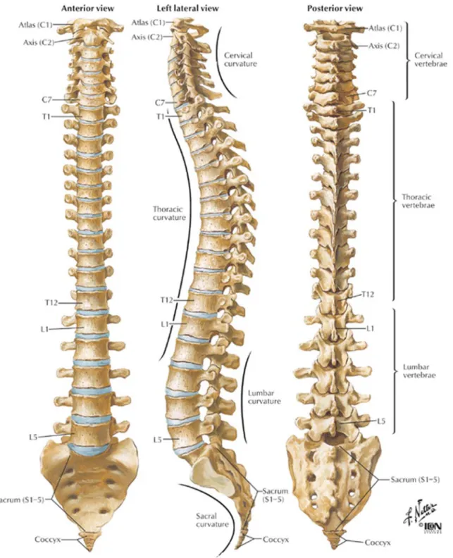
Figure 2.1: Vertebral column: Anterior, left lateral and posterior views of the major
regions of the spine ... 7
Figure 2.2: The motion segment in the lumbar spine, which composed of two vertebrae and surrounding soft tissue ... 8
Figure 2.3: The Shape of a human vertebra: (A) Superior view of the typical lumbar vertebra. (B) The trabecular structure of a lumbar vertebral body in sagittal section ... 9
Figure 2.4: In the intervertebral disc, the annulus fibrosus, made up of laminar layers of criss-crossed collagen fibers, surrounds the nucleus pulposus ... 10
Figure 2.5: Orientation of lumbar facet to the transverse plane (left) and the frontal plane (right) ... 11
Figure 2.6: The major ligaments of the spine ... 12
Figure 2.7: Spinal Cord and Nerve Roots ... 13
Figure 2.8: The radiograph shows the spinal instability ... 15
Figure 2.9: Mono-segmental lumbar spinal stenosis at L4-L5 segment ... 16
Figure 2.10: Multi-segmental lumbar spinal stenosis at L3-L5 segment ... 16
Figure 2.11: Pathoanatomical illustration of lumbar spine stenosis ... 17
Figure 2.12: Pedicle screw instrumentation ... 19
Figure 2.13: X-STOP ... 22
Figure 2.14: Wallis ... 22
Figure 2.15: DIAM ... 22
Figure 2.16: Coflex and Coflex-F ... 22
Figure 2.17: This radiograph demonstrates a solid bony union between L3 and L4 ... 24 Figure 2.18: Common surgical techniques for insertion of a spinal cage. The black arrow
indicates the ALIF approach, the red arrow indicates the PLIF approach, and
the blue arrow indicates the TLIF approach ... 25
Figure 2.19: Various lumbar interbody fusion cages: (A) SynCage-Open (Synthes Spine, Inc., Mathys Medical Ltd., Bettlach, Switzerland); (B) O.I.C. (Stryker Spine, Mahwah, New Jersey, USA); (C) AVS-TL (Stryker Spine, Mahwah, New Jersey, USA) ... 27
Figure 2.20: Interbody fusion combined with posterior pedicle screw fixation ... 27
Figure 2.21: Coflex-F device ... 28
Figure 2.22: unilateral pedicle screw fixation and translaminar facet screw fixation ... 29
Figure 3.1: Each spinal component was selected from computed tomography scan DICOM file to create material-related contours ... 32
Figure 3.2: Modeling process of the L3 vertebra: (A) surface geometries of vertebra were reconstructed through sequential processed computed tomography scan DICOM file; (B) surface geometry was exported to the DXF file; (C) FE model of the L3 vertebra ... 33
Figure 3.3: Finite element model of the L1 to L5 segments is shown: (A) intact model; (B) transverse views of facet joint curvature and gap ... 34
Figure 3.4: Convergence test of the intact model: (A) three mesh densities were selected; (B) result of motion changes under flexion; (C) result of motion changes under extension; (D) result of motion changes under axial rotation; (E) result of motion changes under lateral bending ... 37
Figure 3.5: Finite element models of the L1-L5 lumbar spine: (A) defect model implanted with Coflexat L3-L4 segment (Coflex model); (B) defect model implanted with Coflex-F at L3-L4 segment (Coflex-F model); (C) defect model implanted with Bilateral Pedicle Screw Fixation ... 40 Figure 3.6: (A) Illustration of traditional vertical preloads; (B) Illustration of follower
xi
load; (C) Intact lumbar spine model with follower load ... 41
Figure 3.7: Range of motion (ROM) calculated for the L1-L5 segments of intact lumbar spine is compared to previous in vitro experiments. (Left) intact lumbar spine without follower load data; (Right) intact lumbar spine with follower load data... ... 42
Figure 3.8: Illustration of the Hybrid test method. (A) Whole spine specimen with various transducers and markers to monitor biomechanical parameters of interest. (B) Appropriate unconstrained pure moment is applied to the intact specimen to produce physiological motions. Resulting main total range of motion (tRoMIntact) is recorded. (C) Unconstrained pure moment is applied to the spinal construct produce main total range of motion tRoMConstruct equal to tRoMIntact ... 44
Figure 3.9: Finite element models: (A) Coflex-F device combined with the TLIF model; (B) Coflex-F device combined with the ALIF model; (C) Pedicle screw fixation combined with the TLIF model; (D) Pedicle screw fixation combined with the ALIF model; (E) AVS-TL cage in the middle portion of the vertebral model; (F) SynCage-Open cage in the middle portion of the vertebral model; (G) Coflex-F device model. ... 49
Figure 4.1: Range of motion normalized to intact model in extension ... 57
Figure 4.2: Range of motion normalized to intact model in flexion ... 58
Figure 4.3: Range of motion normalized to intact model in lateral bending ... 58
Figure 4.4: Range of motion normalized to intact model in axial rotation ... 59
Figure 4.5: Disc annulus stress normalized to intact model in extension ... 61
Figure 4.6: Disc annulus stress normalized to intact model in flexion ... 61
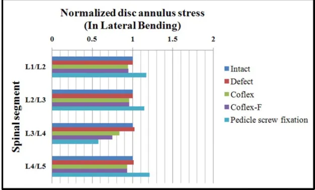
Figure 4.7: Disc annulus stress normalized to intact model in lateral bending ... 62
Figure 4.9: von-Mises stress distribution of disc annulus in extension for various surgical models: (Top) L2-L3 adjacent segment; (Middle) L3-L4 surgical segment;
(Bottom) L4-L5 adjacent segment. ... 63
Figure 4.10: von-Mises stress distribution of disc annulus in flexion for various surgical models: (Top) L2-L3 adjacent segment; (Middle) L3-L4 surgical segment; (Bottom) L4-L5 adjacent segment ... 65
Figure 4.11: von-Mises stress distribution of disc annulus in right lateral bending for various surgical models: (Top) L2-L3 adjacent segment; (Middle) L3-L4 surgical segment; (Bottom) L4-L5 adjacent segment. ... 66
Figure 4.12: von-Mises stress distribution of disc annulus in right axial rotation for various surgical models: (Top) L2-L3 adjacent segment; (Middle) L3-L4 surgical segment; (Bottom) L4-L5 adjacent segment ... 67
Figure 4.13: Range of motion normalized to intact model in flexion ... 70
Figure 4.14: Range of motion normalized to intact model in extension ... 70
Figure 4.15: Range of motion normalized to intact model in left lateral bending ... 70
Figure 4.16: Range of motion normalized to intact model in right lateral bending ... 70
Figure 4.17: Range of motion normalized to intact model in left axial rotation ... 71
Figure 4.18: Range of motion normalized to intact model in right axial rotation. ... 71
Figure 4.19: The von-Mises stress distribution on the cage-bone interfaces of the superior surface of the L4 vertebra under left lateral bending and right lateral bending. . 72
Figure 4.20: The von-Mises stress distribution on the cage-bone interfaces of the superior surface of the L4 vertebra under left axial rotation and right axial rotation. ... 73
Figure 4.21: The von-Mises stress distribution on the cage-bone interfaces of the superior surface of the L4 vertebra under flexion and extension. ... 73 Figure 4.22: The von-Mises stress distribution in the Coflex-F device and the pedicle
xiii
rotation. ... 74
Figure 4.23: The maximum von-Mises stress of the Coflex-F device and pedicle screw under flexion, extension, right lateral bending, and right axial rotation ... 75
Figure 4.24: Range of motion normalized to intact model in flexion ... 76
Figure 4.25: Range of motion normalized to intact model in extension ... 76
Figure 4.26: Range of motion normalized to intact model in right lateral bending ... 77
Figure 4.27: Range of motion normalized to intact model in left lateral bending ... 77
Figure 4.28: Range of motion normalized to intact model in right axial rotation ... 77
Chapter 1 Introduction
1.1 Overview
Degeneration of the intervertebral disc, called degenerative disc disease (DDD) of the spine, is a condition that can be painful and can greatly affect the quality of patient's life. Spinal diseases from DDD become more and more serious and dangerous for human population. Affecting up to 85 % of population at some point in their lifetime, the problem of low back pain reached epidemic proportions in the United States [1]. It has become one of the leading reasons why patients seek treatment, and it has been estimated to cost the national economy over $50 billion per year [2][3]. These diseases cost large medical resources, and add huge encumbrances for our society.
1.2 Motivation and objectives
Recently, the concept of using non-fusion surgery via dynamic stabilization device to treat DDD has become popular. A dynamic stabilization device has been defined as: a flexible system that can preserve the spinal movement and improve load transmission of spinal motion segments through the non-fusion technique. In other words, such a system would restrict motion in the direction or plane that produces pain or painful motion [4]. The concept of dynamic stabilization device has changed from traditional stable fusion to mobile non-fusion that attempts to lessen the deterioration of the adjacent element. There have been a number of dynamic stabilization devices trialed in lumbar spinal disease, many with differing biomechanical principles. Some examples include anterior artificial disc, dynamic pedicle screw system, and interspinous process device.
Currently, there exist a number of interspinous process devices that have been tested for treating lumbar spinal stenosis from slightly degenerative disc disease with different biomechanical designs such as Coflex, Wallis, Diam, and X-Stop. The Coflex (Paradigm
2
Spine, Wurmlingen, Germany) is one of non-fusion spinal implants that was developed to restore normal physiological motion and to overcome the disadvantage of decompression surgery procedure. The Coflex was originally developed as an interspinous U-shaped device and is placed between two adjacent spinous processes. After implantation, the lateral wings are crimped toward the spinous processes to improve fixation. The U-shaped structure is designed to allow the lumbar spine to have controlled movement in forward and backward bending. To improve stability in all motions, a modified version called the Coflex-F has also been developed, which adds a rivet to the Coflex.
The Coflex devices are primarily used for lumbar spinal stenosis (LSS) without degenerative spondylolisthesis, angular instability, and retrolisthesis. Only a few reports of in vitro flexibility tests of the Coflex device are available in the literature. Among them, results regarding the biomechanical effects of the Coflex device at the surgical segment are inconsistent [56][57][59], especially the stability in lateral bending and axial rotation. The short-term clinical reports indicated that Coflex could provide physiological motion-sparing tend to the healthy spinal disc and reduce adjacent segment effect in flexion-extension [5]. However, the long-term outcome of these patients and other motion are still not clear. In addition, these existing studies are mostly concerning a short-segment analysis focused on the surgical segment. The effect of Coflex and Coflex-F device on adjacent segments is still not clear.
In order to understand the results of initial post-surgery and long-term complication of segment disease, and effect of implantation on adjacent segments, a number of biomechanical researches have intervened in evaluating various spinal implants, whether to use of in vitro experimental test or finite element (FE) analysis. However, in Taiwan, human cadaveric lumbar spine specimen is difficult to obtain for the experimental study.
Therefore, the first subject was to investigate the biomechanical behavior between the Coflex and Coflex-F devices at surgical and adjacent segments by using FE analyses on a
five-segment spinal model.
In addition, spinal fusion is a commonly performed surgical procedure to treat serious degenerative disc disease. In order to provide a stable environment for fusion, the use of pedicle screw fixation is usually necessary. Recently, the Coflex-F, which has been claimed to provide stabilization of the posterior spine elements similar to pedicle screw fixation, was adopted to interbody fusion in minimally invasive surgery.
Therefore, the second subject was to investigate the biomechanical behavior of the Coflex-F device and pedicle screw fixation, in combination with anterior lumbar interbody fusion (ALIF) or transforaminal lumbar interbody fusion (TLIF).
All types of interbody fusion approaches are recommended for combination with traditional bilateral pedicle screw fixation to increase stabilization and fusion rates. In the evolving surgical trend of minimally invasive spinal surgery, recent authors have employed TLIF and unilateral pedicle screw fixation. Besides, some surgeons purport that the unilateral pedicle screw fixation may be as effective as bilateral fixation. However, Goel [107] had compared that unilateral and bilateral pedicle screw fixation by in vitro biomechanics, in vivo biomechanics, and finite element method. His results showed that unilateral pedicle screw fixation was less stability than bilateral fixation. Therefore, supplementing the unilateral pedicle screw fixation using a percutaneous facet screw has been suggested as a means of stabilizing a TLIF construct employing unilateral pedicle screws. However, the Translaminar facet screw fixation requires long passage through the lamina for the crossing screws before they can traverse the facet joint, and necessitating a large surgical field. Recently, the Coflex-F has been adopted to combine interbody fusion in minimally invasive surgery; however, the effectiveness of this procedure is still unclear.
The third subject was to investigate the biomechanical characteristics of TLIF combined with Coflex-F and supplemented with one unilateral pedicle screw fixation and one translaminar facet screw fixation implanted into the L3-L4 segment in minimally invasive
4 lumbar fusion.
1.3 Outline
This dissertation is divided into six chapters:
(1) Introduction: this chapter introduces the overview, objectives, and outline of this dissertation.
(2) Background: this chapter reviews the spine anatomy and biomechanics, spinal pathology and treatments, decompression, fusion surgery and non-fusion surgery.
(3) Materials and Methods:
1. The first subject includes FE modeling of the five-segment intact lumbar spine, defect lumbar spine, Coflex implantation, Coflex-F implantation, and Pedicle Screw Fixation models.
2. The second subject includes TLIF and ALIF combined with Coflex-F or with pedicle screw fixation models.
3. The third subject includes TLIF combined with Coflex-F or with unilateral pedicle screw fixation and translaminar facet screw fixation models.
(4) Results:
1. The first subject includes data of intact lumbar spine, defect lumbar spine, both implant models under the Coflex or Coflex-F, and pedicle screw fixation.
2. The second subject includes data of intact lumbar spine, TLIF and ALIF combined with Coflex-F model, TLIF and ALIF combined with pedicle screw fixation model. 3. The third subject includes data of intact lumbar spine, TLIF combined with Coflex-F
model, TLIF combined with unilateral pedicle screw fixation and translaminar facet screw fixation models
(5) Discussion:
2. The second subject finds effect of TLIF and ALIF combined with Coflex-F. 3. The third subject finds effect of TLIF combined with Coflex-F.
4. Model limitations.
(6) Conclusion and Future Work: several topics can be extended from this research is introduced in this chapter.
6
Chapter 2 Background
The following sections contain a review of the anatomy of the spine, its biomechanics, spine pathology and treatments, fusion and non-fusion techniques, clinical outcomes after interspinous process device, and the characteristics of in vitro tests versus FE simulations.
2.1. Spine anatomy and biomechanics
The spine consists of a curved stack of 33 vertebra divided structurally into five regions
(Figure 2.1). Proceeding from superior to inferior, there are seven cervical vertebrae (C1-C7), twelve thoracic vertebrae (T1-T12), five lumbar vertebrae (L1-L5), five fused sacrum vertebrae (S1-S5), and four small fused coccygeal vertebrae. The vertebrae from each region have similar parts, but the shapes of vertebrae vary considerably from region to region in the spine. There may be one extra vertebra or one less, particularly in the lumbar region.
Because of structural differences and the ribs, varying amounts of movement are permitted between adjacent vertebrae in the cervical, thoracic, and lumbar portions of the spine. Within these regions, two adjacent vertebrae and the soft tissues between them are known as a motion segment. The motion segment is considered to be the functional unit of the spine (Figure 2.2).
Each motion segment contains three joints. The vertebral bodies separated by the intervertebral disc form a symphysis type of amphiarthrosis. The right and left facet joints between the superior and inferior articular processes are diarthroses of the gliding type that are lined with articular cartilage.
Figuure 2.1: Verttebral colummn: Anteriorr, left latera the spine
al and poster e [6].
Fig 2.1 the p verte The (Figu resist the v gure 2.2: Th 1.1. Vertebr A typical v pedicle, lam ebral body c vertical and ure 2.3 b). ted by the c vertebral siz he motion se ral vertebra con mina, spinou consists of a d horizontal Most of th cancellous b ze is progres egment in th surro nsists of a b us process, a an outer she l structure o he compres bone becaus ssively incre 8 he lumbar sp ounding sof body, a hollo and transve ell of cortica of bone in t ssive force se of its den eased from pine, which ft tissue [7]. ow ring, an erse process al bone and the cancello acting dow nse network the cervical h composed d several bo , as shown an inner co ous core is wn the long of trabecul l region to t of two vert ony process in Figure 2 ore of cance called trabe g axis of th lar bone [8] the lumbar r tebrae and ses, such as 2.3(a). Each ellous bone. ecular bone he spine is . In general region. s h . e s l,
Figu 2.1 fibro sligh nucle consi whic to th ure 2.3: The [7]. (B) T 1.2. Interver The interv osus (Figure htly compre eus fills 30 ists of appr ch contain c he horizonta e Shape of a The trabecul rtebral disc vertebral dis e 2.4). The essible and % to 50 % oximately 1 collagen fib al plane and a human ver ar structure sc is comp nucleus pul with 80 % % of the tota 15-25 conce ers [12]. Th d crisscross rtebra: (A) S e of a lumba osed of tw lposus loca % to 88 % al disc area entric lamel he collagen to each oth Superior vie ar vertebral wo parts: th ted in the c water cont a in cross-se llae in the c n fibers are her in the ad ew of the ty body in sag he nucleus p central of ea tent [10]. In ection [11]. ircumferent oriented app djacent lam ypical lumba gittal section pulposus a ach disc wh n general, . The annul tial around pproximately mella. The su ar vertebra n [9]. nd annulus hich is only the lumbar lus fibrosus the nucleus y 30° angle uperior and s y r s s e d
infer body The t the o bend norm body F 2. (Figu spina assis resist rior cartilagi The primar y to the nex tensile prop outer region ding and twi mally behave y but also pr Figure 2.4: I cr 1.3. Facet j The size a ure 2.5). Th al regions. I t in load be t rotational inous endpl ry function xt, while al perties of th n being stiff isting of ad e like a flui revents rapi In the interv riss-crossed oint and angulati his changes In addition t earing. The torsion and lates cover d of the disc i lowing for e annulus a fer than the djacent verte
id. The endp d fluid loss vertebral dis d collagen fi ion of the v the orientat to channelin facet joints d shear, with 10 disc and con is transfer c small-ampl are stiffer in e inner regio ebrae, while dplate not on from the nu sc, the annu fibers, surro vertebral pr tion of the f ng the move s and discs h half of this nnect with a compressive litude twist anterior tha ons [14]. Th e the innerm nly helps to ucleus [15]. ulus fibrosu unds the nu rocesses va facet joints, ement of th provide ab s contributi adjacent ver e forces eve ting and slid
an the poste he outer lam most lamell o equalize lo . s, made up ucleus pulpo ary througho which limit e motion se out 80 % o on from the rtebrae bodi enly from on ding movem erolateral re mellae resis lae are defo oading of th
of laminar osus [7].
out the spin it ROM in th egment, the of the spine e facet joint ies. ne vertebral ments [13]. egions, with st excessive ormable and he vertebral layers of nal column he different facet joints ’s ability to s [16] [17]. l . h e d l n t s o
Fi 2. Impo ligam betw surfa canal on th ligam verte along igure 2.5: O 1.4. Spinal There are a ortant to the ment (ALL) ween the ve aces of the v l along the he back surf ment (ISL) r ebra) to ano g the tips of Orientation o ligaments a series of li e lumbar spi ) and poste ertebrae. Th vertebral bo back surfac face of the c runs from th other. Intert f the spinou of lumbar fa igaments th ine are seve erior longitu he anterior odies. The p ce of the ve canal where he base of o transverse l us processe acet to the tr (right) [
hat are impo en types of tudinal liga longitudina posterior lon ertebral bod e the spinal one spinous ligament (I s. Joint-rela ransverse p [7]. ortant to the ligaments ( ment (PLL al ligament ngitudinal l dies. The lig
cord or cau s process (th ITL) and su ated structur lane (left) a e stability of Figure 2.6) L) are assoc t runs along ligament run gamentum f ude equina he projectio upraspinous res called f
and the fron
f the verteb : Anterior l ciated with ng the front ns within th flavum (LF runs. The in ons at the b s ligaments facet capsul ntal plane ral column. longitudinal each joint t and outer he vertebral F) is located nterspinous ack of each (SSL) run ar ligament . l t r l d s h n t
(CL) 2. The i and d of th Foram joint the in 2. (Figu top o sever ) also play a 1.5. Neural The segme intervertebr dorsally by he intervert minal disc h capsule of ntervertebra 1.6. Spinal The spina ure 2.7). It e of second lu ral different an importan Figur l foramen ental spinal ral foramen two major ebral disc herniations f the articula al foramen. cord and ne al cord is a extends from umbar vert t groups of t role in stab re 2.6: The nerve root is bounded interverteb and the lat can imping ar facets an The remain erve roots column of m the brain ebra. At th fibers that f 12 abilization a major ligam ts exit throu d by the ped bral articula teral expans ge on the ex nd the ligam ning space i f millions o to the area he second lu
form the ner
nd moveme
ments of the
ugh the inte dicles super ations. It is sion of the xiting nerve ment flavum s composed of nerve fib between th umbar verte rves that wi ent. e spine [18]. ervertebral riorly and in bounded ve posterior e root, causi m make up t d of loose ar
ers that run he end of fir ebra, the sp ill go to the . foramen (F nferiorly, an entrally by longitudina ing radiculo the dorsal b reolar tissue n through s rst lumbar v pinal cord d lower half Figure 2.2). nd ventrally the dorsum al ligament. opathy. The boundary of e and fat. spinal canal vertebra and divides into of the body . y m . e f l d o y.
For a neura spina form spina the s spina paral nerve go to bladd musc a small dist al foramen. al canal. A protectiv ms a waterti al cord is su The nerve mall openin al cord conn lysis in cert es of the ce o chest and der. These cles. ance, the ne This collec ve membran ght sack ar urrounded b fibers in sp ngs (foramin nect to spec tain areas an ervical spine d abdomen. nerves coo Fig erves actual ction of ner ne called th round the s y spinal flu inal cord br na) between cific parts of nd not othe e go to the The nerve ordinate an gure 2.7: Sp lly travel th rves is calle he dura ma spinal cord uid. ranch off to n vertebrae f body. This ers; it depen upper ches es of the lu nd control a inal Cord an hrough the s ed the cauda ater covers and the sp form pairs and vertebr s is why dam nds on whic st and arms. umbar spine
all the bod
nd Nerve R spinal canal a equina wh the spinal inal nerves of nerve ro rae. The ner mage to the ch spinal ne . The nerve e then reac dy's organs Roots [19]. l before exit hile it is stil cord. The s. Inside thi
oots that tra rves in each e spinal cord erves are af es in the tho ch to legs, and parts,
ting out the ll inside the dura mater is sack, the vel through h area of the d can cause ffected. The oracic spine bowel, and , and body e e r e h e e e e d y
14 2.2. Spinal pathology and treatments
The functions of spine are to provide the longitudinal weight support, limit excessive movement, and protect posterior spinal cord. However, the spinal instability may induce due to several pathological changes, such as degenerative disc disease, spinal deformity, tumor, infection, trauma, congenital anomaly, inflammatory, etc (Figure 2.8). Thus spinal nerve roots or spinal cord may be compressed and leading low back pain (Figure 2.9). The first choice of treatment for low back pain is conservative therapy, such as physical therapy or medication. When conservative treatments fail, spine surgeons may perform either fusion or non-fusion surgery, with the arm of reducing pain and decreasing disability [20].
2.2.1. Lumbar spinal stenosis
The most common cause of lumbar spinal stenosis (LSS) is initial stage of degeneration intervertebral disc. LSS defined as narrowing of the spinal canal or intervertebral foramina, is a common cause of pain, numbness, and weakness. Early descriptions of neurogenic claudication secondary to lumbar stenosis have been attributed to Verbiest [22]. This syndrome is displayed by radicular pain, which is exacerbated by standing, walking, and other positions that place the lumbar spine in extension. A flexed posture improves or relieves the symptoms. In severe cases, sensory loss or motor deficits are evident. Although several theories have been postulated to explain the occurrence of these symptoms, the precise mechanism remains unclear [23]. It is obvious that the pathological progression begins with degeneration of disc, which finally leads to loss of disc height. Resultant instability may worsen the spondylosis by inducing facet joint hypertrophy [24]. Furthermore, hypertrophy of the ligamentum flavum, particularly during extension, contribute to the reduction in size of the thecal sac limiting the space available for the cauda equine [4].
LSS can be mono-segmental or multi-segmental (Figure 2.10), and unilateral or bilateral. Anatomically, the stenosis can be classified as central, lateral or foraminal [21]. Depending on
the d comb L5-S narro of in (fora facet cysts reduc press to loo in th centr degree of d bination. Th S1, and S1-S owing of the ntervertebra aminal steno t joint arthro s (lateral st ced height sure on the osened tend he soft tissu ral canal [25 degeneratio he L4-L5 sp S2 [25]. De e spinal can al space is osis), exerti osis, hypert tenosis), w of the segm spinal dura dons (ligam ue and osteo 5]-[33]. Figure 2.8 n, central, pinal discs a generation nal (Figure 2 reduced, ing strain o rophy of th which in co ment leads from the do entum flavu ophytes, cre 8: The radio lateral and are most fre
of disc ofte 2.11). As a which cau on the facet he joint caps ombination the ligame orsal side (c um) further eating the c ograph show d foraminal quently affe en causes a consequenc uses the int joints. Suc sules and th propagate entum flavu central sten propagates characteristi ws the spinal l stenosis c ected by LS protrusion, ce of disc de tervertebral ch an increa e developm spinal inst um to form osis). Conc preexisting c trefoil-sha l instability can occur a SS, followed which lead egeneration l foramina ase in load ment of expa tability [25 m creases, w comitant ins g hypertroph aped narrow y [21]. alone or in d by L3-L4, ds to ventral n, the height to narrow can lead to anding joint 5][26]. The which exert tability due hic changes wing of the n , l t w o t e t e s e
Figure Figure e 2.9: Mono 2.10: Multi o-segmental i-segmental 16 lumbar spi l lumbar spi nal stenosis inal stenosis s at L4-L5 s s at L3-L5 s segment [25 segment [25 5]. 5].
18 2.2.2. Conservative therapy
The conservative treatment of LSS comprises a wide variety of methods, such as ergotherapy, physical therapy, behavioral therapy, girdles, acupuncture, manual therapy and pharmacological intervention. Few studies have been conducted to demonstrate the effectiveness of conservative therapy in treating LSS, although those that reported had success rates of up to 70 % [25][34]-[36]. However, none of the available studies provide sufficient data to support the effectiveness, or any one of the wide range of conservative treatments [37]. In the absence of evidence-based clinical guidelines, multidisciplinary approach should be given preference over a significant therapy [38][39].
2.2.3. Decompression surgery
In patients in whom severe symptoms persist and functional impairment develops, surgery is the recommended option. Decompression surgery used in LSS aim to decompress the neural elements, without occur instability of the segment. Such decompression surgery usually leads to relief of pain in the legs and low back pain [41]. Decompressive surgical procedures include laminectomy and hemilaminectomy, hemilaminotomy, fenestration, and foraminotomy [40]. The complication rates for decompression surgery range from 14 % to 35 % or more [42]-[45]. Typical complications of decompression surgery include inadequate decompression with significant residual stenosis, instability of segment, renewed nerve compression, and reossification. All of these complications result in renewed nerve compression [44]-[47].
Decompression surgery may cause as mentioned above if weight bearing structures are compromised. Therefore, instrumented is necessary when preexisting or surgically induced instability is present. Pedicle screw instrumentation is a popular method of strong fixation to achieve stabilization rate (Figure 2.12). For stabilization of one spinal functional unit, four pedicle screws are usually used.
risks Neur 3. Im 2.2 dyna Inter and g distra syste neve interv lumb However, t . Complica rological co mplant failur 2.4. Non-fu Two such amic manne rspinous pro generally sp acting acros ems utilize rtheless all vertebral fle The basic r bar spinous the use of p ations were omplications res: malposi Fi usion surgery technologi er, such as in ocess devic peaking, atte ss the interv a non-rigi low for dis exion throu rationale of processes pedicle screw divided in s: postopera ition, break igure 2.12: y cal strategi nterspinous e are insert empt to red vertebral dis id means o traction acr gh band tec f interspinou as a treatm ws is techni nto three ca ative neurap kage or loss Pedicle scre ies have em process dev ted between duce neural sc, or promo of connecti
ross the int chnology. us process ment for st ically dema ategories: 1 praxias or p of correctio ew instrume merged for vice [51] an n the spinou compressio oting lumba ng otherwi tervertebral device for tenosis is th anding and a 1. Infection permanent n on [49]. entation [50 managing nd dynamic us processe n by preven ar flexion. D ise standard l disc or re inserting an hat the sym
associated w ns: deep in neurologica 0]. lumbar ste c pedicle scr es of the lum nting lumba Dynamic pe d pedicle s egulate the n implant b mptoms of with certain fections. 2. al disorders. enosis in a rew system. mbar spine, ar extension edicle screw screws that amount of between the neurogenic n . . a . , n, w t f e c
20
claudication are often relieved with the lumbar spine in the flexed position, and worsened in extension. Conceptually, a device that induced some flexion of the motion segment would increase the caliber of the spinal canal and the intervertebral foramen. Furthermore, if such a device merely prevented extension, it could minimize the narrowing of the spinal canal and foramen observed with extension. Additionally, and interspinous process device might also provide for some degree of distraction which could unload both the facet joints and intervertebral discs, potentially reducing back pain. Finally, on a practical note, the ability to access the interspinous area with a small incision and minimal paraspinal muscle stripping implies that the implantation of such a device could be performed in much less traumatic way than current decompression techniques. The interspinous process device can be called the non-fusion surgery is to restore normal physiological motions, or to allow restrained motions within a certain range, through various mobile non-fusion devices that aim to avoid or alleviate adjacent segment disease.
Four such interspinous process devices have been designed and are currently available: the Coflex(Paradigm Spine, Wurmlingen, Germany), the Wallis (Abbott spine, Bordeaux, France), the Diam (Medtronic, Tolochenaz, Switzerland), and X-Stop (Medtronic, Tolochenaz, Switzerland). As a general note, at the time of this writing, the four devices described here are in various stages of clinical development.
(1) X-STOP
The X-STOPconsists of a titanium oval spacer with two lateral wings to prevent lateral migration (Figure 2.13). It is inserted into the interspinous space without disruption of the interspinous ligament. A biomechanical study demonstrated that the force required to insert the device in the appropriate position is 4.5 times less than the force required to break off the spinous process with the device placed too caudally or cranialy, suggesting that the device insertion is relatively safe. The body of biomechanical and clinical literature for the X-STOP far exceeds that of the other devices and as such it is described in the most detail here. It has
been formally evaluated in patients with computed tomography or MRI confirmed lumbar stenosis who complained of leg, buttock, or groin pain relieved by flexion, with or without back pain. In one article, it is speculated that the implant may confer some benefit to patients with pressure-related discogenic back pain, under the hypothesis that the implant provides some distraction and thus decreases pressure within the intervertebral disc.
(2) Wallis
The Wallis system consists of an interspinous blocker made from PEEK (Polyetheretherketone) with two woven Dacron ligaments which wrap around the caudal and cranial spinous processes (Figure 2.14). The interspinous ligament is removed and the Dacron ligaments are inserted around the caudal and cranial spinous processes. At the end of the procedure, the interspinous ligament is repaired. The designer of this device advocates the following indications for its implantation: recurrent disc herniation after primary discectomy, primary discectomy for voluminous herniated disc, discectomy for herniation of a transitional disc segment, disc degeneration adjacent to a previous fusion, and isolated Modic I lesion leading to chronic low back pain.
(3) DIAM
The DIAM for intervertebral assisted motion, is an interspinous implant that consists of a silicone core surrounded by a polyester outer mesh which is secured to the cephalad and caudal spinous processes by two polyester tethers (Figure 2.15). These tethers are inserted through the interspinous processes using attached steel needles and then are secured to the device by means of two titanium crimps.
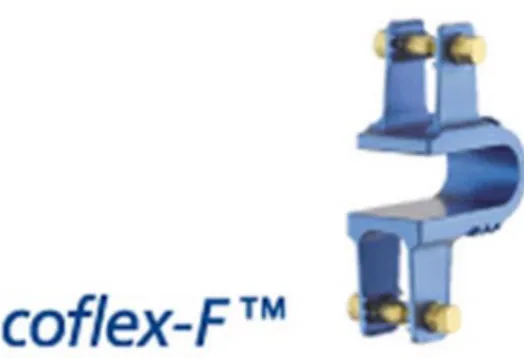
(4) Coflex and Coflex-F
The Coflex device is made of titanium. It was originally developed as an interspinous U-shaped and is placed between two adjacent spinous processes (Figure 2.16) [52][53][54]. After implantation, the lateral wings are crimped towards the spinous processes to improve fixation. The U-shaped structure is designed to allow the lumbar spine to have controlled
move versi Cofle ement in fo ion called th ex [56]. Fi orward and b he Coflex-F igure 2.13: X backward b F (Coflex ri X-STOP [5 Fig Figure 2.16 22 bending. To
ivet) has als
5] gure 2.15: D 6: Coflex an o improve st so been dev Figu DIAM [55] nd Coflex-F tability in a veloped, wh ure 2.14: Wa F [56]. all motions, hich adds a allis [55] a modified rivet to the d e
Recently, many studies have evaluated the biomechanical behaviors of the Coflex and Coflex-F devices. Tsai [57] used cadaveric lumbar L4 and L5 segments with implanted Coflex device to examine their biomechanical behavior, and the results showed that the implanted Coflex device can provide stability for the lumbar spine in flexion-extension and axial rotation, except in lateral bending. Kong [58] reported 1-year follow-up outcomes after Coflex device implantation and traditional fusion for degenerative spinal stenosis. The results indicated that both the Coflex device and traditional fusion reduced the range of motion (ROM) at the surgical segment, but fewer effects were found at the adjacent segments with the Coflex device as compared with the increasing ROM with traditional fusion. Kettler [56]
compared the Coflex and Coflex-F devices using biomechanical experiments and found that both implants had strong stability in extension. However, the Coflex implant could not compensate the instability in flexion, lateral bending, and axial rotation as well as the Coflex-F did. Wilke [59] examined the biomechanical effects of different interspinous process devices for flexibility. The Coflex device had the best stabilizing effect in extension but poor stability in flexion. In lateral bending and axial rotation, the Coflex device had neither a stabilizing nor a destabilizing effect. Inconsistent results regarding the biomechanical effects of the Coflex device have been shown in previous studies. In addition, these studies are mostly a short-segment analysis focused on the surgical segment. The effect of the Coflex device and the Coflex-F device on adjacent segments is still not clear.
Therefore, the first subject was to investigate the biomechanical differences between the Coflex device and the Coflex-F at surgical and adjacent segments by using finite element (FE) analyses on a five-segment spinal model. In addition, the study also compared these two interspinous process implantations with pedicle screw fixation.
2.2 vertic of a becau surge facto co-m mani (Figu final the a verte verte adop F 2.5. Fusion Fusion surg cal mobility lumbar ver use instabi ery in cases ors such a morbidities [ Spinal fusi ipulation [6 ure 2.17). It goal of the anterior spi ebral bodies ebrae. These pted from fib
Figure 2.17: surgery gery is nee y of the ver rtebra relativ ility can m s of LSS ran as type of [60]-[67]. on is define 68], and ai t is an effec e procedure inal column s to mainta e bone graft bulae, illia, This radiog ded in case rtebral body ve to one b make nerve nge from 40 f decompre ed as a bony ims to com ctive techni is to restor n. In gener ain disc he fts may be a the iliac cre
graph demo 24 es of severe y >3 mm), s below) or sc root comp 0-90 % in th ession, dur y union betw mpletely eli
ique for tre re disc heigh ral, bone gr eight and to autografts, a est, or ribs. onstrates a s e degenerati spondylolist coliosis (late pression. S he literature ation of f ween two ve iminate mo ating degen ht, enlarge rafts are pl o accelerat allografts or solid bony u ion disc, in thesis (>5 m eral curvatu Success rate e and depen follow-up, ertebrae spa ovement by nerative spin the stenotic laced into e bone gro r synthetic m union betwe nstability (ro mm forward ure of the s es for dec nd on a wid age of pa aces followi y the motio nal instabili c foramen, a the interfac owth into n materials wh een L3 and L otational or d movement pine) >20°, ompression e variety of atients and ing surgical on segment ity, and the and support ce between neighboring hich can be L4 [69]. r t , n f d l t e t n g e
as th (PLIF ALIF the n the P inclu nucle more modi spine (Figu Fi indi interv featu The most c he anterior l F) approach F approach nucleus befo PLIF approa udes the rem eus. In addi e space (Fig ified from t e is approac ure 2.18; blu igure 2.18: C icates the A The spinal vertebral b ures of this common sur lumbar inte h, and transf includes the ore implant ach, a partia moval of the ition, a certa gure 2.18; re the PLIF me ched, an inf ue arrow) [7 Common su ALIF approa interbody ody, thus r device (Fi rgical techn erbody fusio foraminal lu e removal o ting an inter al laminecto e ISL, SSL, ain portion ed arrow) [7 ethod to pro ferior hemi-72]. urgical tech ach, the red indica fusion cage restoring ph igure 2.19). niques for th on (ALIF) a umbar inter of the ALL, rbody fusio omy, discec LF, posteri of the facet 71]. Recentl ovide a min -laminectom hniques for i arrow indic ates the TLI
e can repla hysiologica . First, the he insertion approach, p rbody fusion the anterior on cage (Fig ctomy and n ior portions t joint can b ly, the TLIF nimally inva my and a un
insertion of cates the PL IF approach
ace the dege al disc heig spinal fusi of a spinal posterior lum n (TLIF) ap r portions o gure 2.18; b nucleotomy of the disc be removed F approach h asive surgic nilateral fac a spinal cag LIF approach h. enerative d ght. In gene on cage is l cage can b mbar interb pproach. In g of the disc a black arrow y are perform c annulus, a to give the has been pr cal techniqu cectomy are
ge. The blac ch, and the b
disc and dis eral, there made of a be classified body fusion general, the nnulus, and w) [70]. For med, which and the total nerve roots roposed and e. After the e performed ck arrow blue arrow stension the are several a variety of d n e d r h l s d e d e l f
26
biocompatible materials, including stainless steel, titanium alloy, carbon fiber-reinforced polymer (CFRP), and polyetheretherketone (PEEK) [73]. Due to the high mechanical strength of these materials, a spinal interbody fusion cage can provide better longitudinal support than a traditional bone graft, without causing collapse. Second, rough or specific designs can be found on the contact surfaces of spinal cages. In order to prevent cage slippage, rough contact surfaces, saw teeth, spikes or threads have been designed to increase stability between fusion devices and endplates. Third, these implants are usually designed to be hollow, with small pore or openings on the wall. These hollow cages can be filled with bone grafts to promote bone growth. Furthermore, only small amounts of cancellous bone are required, because there is no longer need for the cubic graft to be a spacer. The small pores and openings on the wall allow the growth of bone through the cage, resulting in bony fusion. Therefore, spinal fusion cages can avoid donor site morbidity and increase fusion rates.
Currently, many kinds of spinal cage designs are available on the market, which can be classified by the various surgical approaches used in their implantation. Large single lumbar cage designs are used for the ALIF procedure (Figure 2.19 A). Some paired cage designs are used strictly for PLIF procedures (Figure 2.19 B). In addition, some specific shapes of cages are designed for minimally invasive surgical techniques such as the TLIF procedure (Figure 2.19 C).
All types of interbody fusion approaches are recommended for combination with traditional posterior pedicle screw fixation to increase stabilization and fusion rates (Figure 2.20). A pedicle screw is a device composed of rods and screws contoured to restore lumbar lordosis and disc height, and can be used for unilateral or bilateral pedicle screw fixation.
Figu Math cond elem techn screw the p in m rivet devic ure 2.19: Va hys Medical U Figure 2.2 The fusion ditions of th ments, maint nically dem ws surgery i Recently, th posterior spi minimally in s modified ce and the s (A) arious lumba l Ltd., Bettl USA); (C) A 20: Interbod n is very su e lumbar sp tenance of manding and include infe he Coflex-F ine element nvasive surg from the o spinous proc ar interbody lach, Switze AVS-TL (Str dy fusion co uccessful in pine. Fusion neural dec d associated ections, neur F (Figure 2. s similar to gery. The C original Cof cesses allow y fusion cag erland); (B) ryker Spine ombined wit n the treatm n provides s compressio d with cert rological ris .21), which pedicle scr Coflex-F sp flex device. w for rigid a (B) ges: (A) Syn ) O.I.C. (Str , Mahwah, N th posterior ment of de stabilization n. Howeve tain risks. T sk and impl has been c rew fixation pacer is an . The rivets attachment t nCage-Open ryker Spine, New Jersey pedicle scre eformity as n of the spin er, the use
Typical com lant failures claimed to p n, was adopt interspinou s joining the to the poste n (Synthes S , Mahwah, N y, USA). rew fixation well as d ne, protectio of pedicle mplications s [49]. provide stab ted to interb us process d e wings of erior elemen (C) Spine, Inc., New Jersey n [74]. egenerative on of neural e screws is of pedicle bilization of body fusion device with the Coflex nt. It retains y, e l s e f n h x s
the a spari incis Cofle surge lamin impla tradit can b was asym stiffn incre How the c field advantages ing tissue, ions, and op Therefore, ex-F device ery. In addi na bone an ant in the in All types tional pedic be used for used with t mmetric con ness. There ease stability wever, the Tr crossing scr [77][78][79 of interspi preserving perating tim the second e and pedic ition, Beca nd spinous nterspinous of fusion cle screw fi unilateral o the TLIF su nstruct will efore, supp y of TLIF c ranslaminar ews before 9]. inous proce pedicle an me, thus spe
Figure 2 d subject w cle screw f use of the process to process. surgery a fixation to i or bilateral p urgery to p result in s lementation combined w r facet screw they can tr 28 ess implant natomy, mi eding patien 2.21: Coflex was to inve fixation, in PLIF surgi get appro approaches increase sta pedicle scre provide stab spine segm n of a tran with unilater w fixation r raverse the ts and mini inimizing m nt recovery. x-F device [7 estigate the combinatio ical process ach which are recom abilization a ew fixation. bility in min ment destabi nslaminar f ral pedicle requires lon facet joint, imally inva muscle trau . 75]. e biomecha on with AL s needed to may make mmended f and fusion r Unilateral nimally inv lization and facet screw screw fixati ng passage t and necess asive surger uma, blood anical behav LIF or TLIF o remove p e the Cofle for combin rates. A ped pedicle scr vasive surge d a decrea w is recom ion (Figure through the sitating a lar ry, such as d loss, skin vior of the F in fusion parts of the ex-F cannot nation with dicle screw rew fixation ery, but the se in spine mmended to 2.22) [76]. e lamina for rge surgical s n e n e t h w n e e o . r l
surge with trans lumb Fi The Coflex ery; howeve The third s Coflex-F slaminar fac bar fusion. igure 2.22: x-F has be er, the effec subject was and suppl cet screw f unilateral p een adopted tiveness of to investiga lemented w fixation imp pedicle screw d to combi this proced ate the biom with one u planted into w fixation a ne interbod dure is still u mechanical unilateral p o the L3-L4 and translam dy fusion i unclear. characterist pedicle scre 4 segment i minar facet s in minimal tics of TLIF ew fixation in minimal screw fixati ly invasive F combined n and one lly invasive ion [76]. e d e e
30
Chapter 3 Materials and Methods
3.1 Coflex and Coflex-F in non-fusion surgery
The first subject of following sections includes FE modeling and simulation technique of this study. Five FE models of the lumbar spine were constructed for this study. The first model was the intact lumbar spine. The other four models were the defect lumbar spine, the defect lumbar spine combined with Coflex, defect lumbar spine combined with Coflex-F, and defect lumbar spine combined with pedicle screw fixation.
3.1.1 FE model of intact lumbar spine (Intact model)
To create a three-dimensional FE model, computed tomography scan DICOM files of the L1 to L5 lumbar spine of a middle-aged male were obtained at 1-mm intervals. The commercially available visualization software Amira 3.1.1 (Mercury Computer Systems, Inc., Berlin, Germany) was used to describe cross-section contours of each spinal component in accordance with gray scale value (Figure 3.1). Then, the three-dimensional surface geometries were constructed through sequential processed cross-section contours as shown in
Figure 3.2 A. Each spinal component was exported as a Drawing eXchange Format (DXF)
file and converted to the Initial Graphics Exchange Specification (IGES) file as shown in
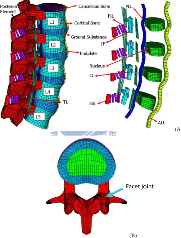
Figure 3.2 B. The FE analysis software ANSYS 9.0 (ANSYS Inc., Canonsburg, PA) was used to reconstruct the FE model by converting the IGES file to ANSYS Parametric Design Language (APDL) code in Figure 3.2 C. The INT model was an osseo-ligamentous lumbar spine, which included the vertebrae, intervertebral discs, endplates, posterior bony elements, and all seven ligaments (Figure 3.3 A).
An eight-node solid element (SOLID185) was used for modeling the cortical bone, cancellous bone, posterior bony element, cartilage endplate, and annulus ground substance. The cortical bone and cancellous bone were assumed to be homogeneous and transversely
isotropic [81]. The posterior bony element and cartilage endplate were assumed to be homogeneous and isotropic [82]. The intervertebral disc consisted of annulus ground substance, nucleus pulposus and collagen fibers embedded in the ground substance. The nonlinear annulus ground substance was simulated by using a hyper-elastic Mooney-Rivlin formulation [83][84]. The collagen fibers simply connected between nodes on adjacent endplates to create an irregular criss-cross configuration. These irregular angles of collagen fibers were oriented within the range of the Marchand’s [85] study. In the radial direction, twelve double cross-linked fiber layers were defined to decrease elastic strength proportionally from the outermost layer to the innermost. Therefore, the collagen fibers in different annulus layers were weighted (elastic modulus at the outermost layers 1-3: 1.0, layers 4-6: 0.9, layers 7-9: 0.75, and at the innermost layers 10-12: 0.65; cross sectional areas at the outermost layers 1-3: 1.0, layers 4-6: 0.78, layers 7-9: 0.62, and at the innermost layers 10-12: 0.47) based on previous studies [86][87]. The nucleus pulposus was modeled as an incompressible fluid with a bulk modulus of 1666.7 MPa by eight-node fluid elements (FLUID80) [81]. The 43 % of the cross-sectional area in the disc was defined as the nucleus, which was within the range of the study by Panagiotacopulos (30-50 %) [88] Therefore, approximately 47 % to 49 % disc volume was assigned to nucleus pulposus. All seven ligaments and collagen fibers were simulated by two-node bilinear link elements (LINK10) with uniaxial tension resistance only, which were arranged in an anatomically correct direction [89]. The cross-sectional area of each ligament was obtained from previous studies
[82][87][90][91], and material properties of the spine are listed in Table 3.1. The facet joint was treated as having sliding contact behavior using three-dimensional eight-node surface-to-surface contact elements (CONTA174), which may slide between three-dimensional target elements (TARGE170). The coefficient of friction was set at 0.1[92]. The initial gap between a pair of facet surfaces was kept within 0.5 mm as shown in Figure 3.3 (b) [81]. The stiffness of the spinal structure changes depending on the contact status, so
the s nonli bend displ probl Fig standard co inear proble ding momen lacement an lem. The IN gure 3.1: Ea ontact optio em in this s nts, thus c nalysis opt NT model co ach spinal c on in ANS study. In ad changing th tion in AN onsisted of component w file to crea 32 SYS was a ddition, the he individu NSYS was 84,584 elem was selected ate material adopted to element’s ual element chosen to ments and 9 d from com l-related con account fo shape will t stiffness. solve this 4,162 node mputed tomo ntours. or the chan change afte Therefore s geometric es [93][94]. ography sca nging-states er applying , the large c nonlinear an DICOM s g e r
Fi re igure 3.2: M econstructed surface g Modeling pr d through se geometry wa rocess of the equential pr as exported e L3 vertebr rocessed co d to the DXF
ra: (A) surf mputed tom F file; (C) F (A) (B) (C) face geometr mography sc FE model of tries of verte can DICOM f the L3 vert ebra were M file; (B) tebra.
Figgure 3.3: Finnite elemen trans nt model of t sverse view 34 the L1 to L ws of facet jo 5 segments oint curvatu (B) is shown: ( ure and gap.
Facet jo
(A) intact m
oint
(A)
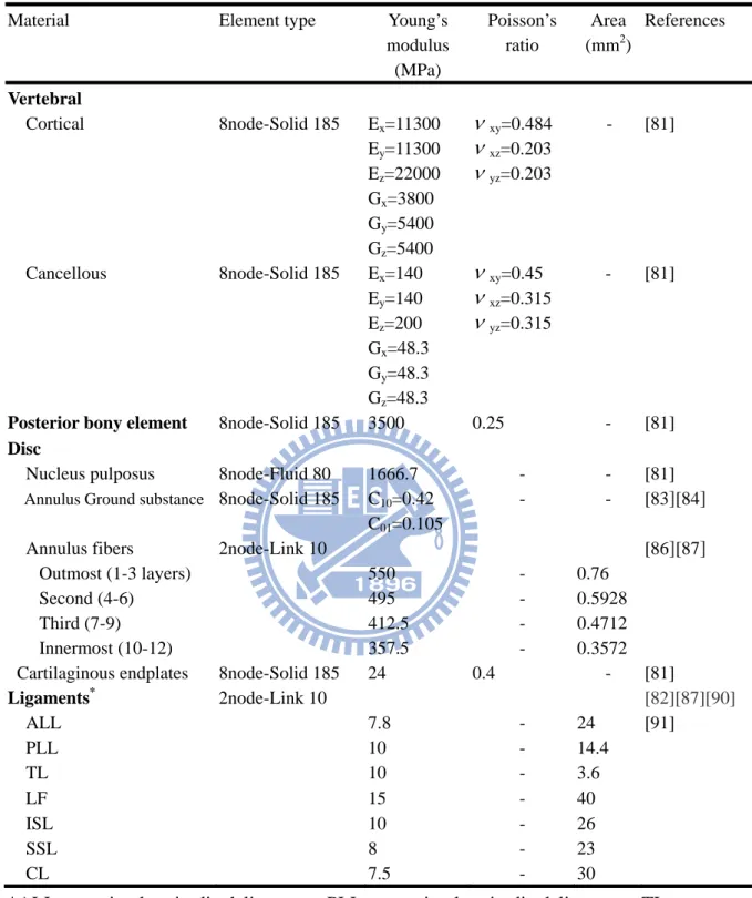
Table 3.1: Material properties used in the FE model
Material Element type Young’s
modulus (MPa) Poisson’s ratio Area (mm2) References Vertebral Cortical 8node-Solid 185 Ex=11300 Ey=11300 Ez=22000 xy=0.484 xz=0.203 yz=0.203 - [81] Gx=3800 Gy=5400 Gz=5400 Cancellous 8node-Solid 185 Ex=140 Ey=140 Ez=200 xy=0.45 xz=0.315 yz=0.315 - [81] Gx=48.3 Gy=48.3 Gz=48.3
Posterior bony element 8node-Solid 185 3500 0.25 - [81]
Disc
Nucleus pulposus Annulus Ground substance
8node-Fluid 80 8node-Solid 185 1666.7 C10=0.42 C01=0.105 - - - - [81] [83][84]
Annulus fibers 2node-Link 10 [86][87]
Outmost (1-3 layers) 550 - 0.76
Second (4-6) 495 - 0.5928
Third (7-9) 412.5 - 0.4712
Innermost (10-12) 357.5 - 0.3572
Cartilaginous endplates 8node-Solid 185 24 0.4 - [81]
Ligaments* ALL 2node-Link 10 7.8 - 24 [82][87][90] [91] PLL 10 - 14.4 TL 10 - 3.6 LF 15 - 40 ISL 10 - 26 SSL 8 - 23 CL 7.5 - 30
*ALL, anterior longitudinal ligament; PLL, posterior longitudinal ligament; TL, transverse ligament; LF, ligamentum flavum; ISL, interspinous ligament; SSL, supraspinous ligament; CL, capsular ligament.
36
In order to get reliable data, convergence test were conducted. Three mesh densities (coarse model: 4,750 elements / 4,960 nodes; normal model: 27,244 elements / 30,630 nodes; finest model: 112,174 elements / 94,162 nodes) were selected to test ROM in the intact model
(Figure 3.4). The boundary and loading conditions of the test were that the inferior surface of L5 vertebra was fixed, and 10 N-m moment and a 150 N preload were applied to the superior surface of L1 vertebra.
Compared with normal model and finest model, the variation of ROM was within 1.03% in flexion (less than 0.2o), 4.39% in extension (less than 0.5o), 0.01% in axial rotation (less than 0.2o), and 0.001% in lateral bending (less than 0.1o). From the simulation results, the normal model only required fewer computational times to complete. However, several contact surfaces in facet joint have stress concentration owed to the lower smooth geometry for fewer elements and nodes. Therefore, the finest mesh density was selected in this study.
Figu res re ure 3.4: Con sult of motio esult of mot nvergence te on changes tion change est of the in under flexi s under axia (B) (D) ntact model: ion; (C) resu al rotation; bendin : (A) three m ult of motio (E) result o ng. mesh densit on changes u f motion ch ( ties were se under exten hanges unde (A) (C) (E) lected; (B) nsion; (D) er lateral
38
3.1.2 FE model of Coflex implanted into the L3-L4 segment (Coflex model)
This model was a defect model implanted with the Coflex device at the L3-L4 segment. The defect model was used to simulate decompression and instability by cutting the ligamentum flavum, the facet capsules, and 50 % of the inferior bony facet bilaterally at the L3-L4 segment [55][57]. The process is designed to remove a small portion of the bone to give the nerve root more space and prevents nerve compression. In addition, the supraspinous ligaments and interspinous ligaments had to be resected before insertion.
The Coflex device is available in five sizes from 8 mm through 16 mm in 2-mm increments. The most suitable size of Coflex device was chosen based on the patient’s lumbar spine. In this study, a height of 14 mm was the best fit to our FE model. The geometry of the Coflex device was re-created by CAD software from the real product and then transferred into the ANSYS software to construct the CoflexFE model. To implant the Coflex device (Figure 3.5 A), part of the L3-L4 interspinous process was removed to provide sufficient space into which the Coflex could be placed between the interspinous processes. The surface between the spinous processes and the wings of the Coflex was modeled as a surface-to-surface contact. The effect of teeth on the wings of the Coflex device was simplified by assigning a higher coefficient of friction (0.8) to the wing contact area (Figure 3.5 A, yellow region), and the coefficient of friction for the rest of the contact regions was set to 0.1 (Figure 3.5 A, red region). The higher coefficient of friction (0.8) was used in the contact interface to prevent device slip motion [86]. The material used for the Coflex device was Ti-6Al-4V alloy. The Young’s modulus and Poisson’s ratio were respectively assigned to be 113 GPa and 0.3.
3.1.3 FE model of Coflex-F implanted into the L3-L4 segment (Coflex-F model)
This model was a defect model implanted with the Coflex-F deviceat the L3-L4 segment. The defect model was used to simulate instability by cutting the ligamentum flavum, the facet capsules, and 50 % of the inferior bony facet bilaterally at the L3-L4 segment [55][57]. In
![Figu ure 2.11: Patthoanatomic cal illustratiion of lumb bar spine ste enosis [25].](https://thumb-ap.123doks.com/thumbv2/9libinfo/8694789.198674/32.892.241.684.108.1100/figu-ure-patthoanatomic-cal-illustratiion-lumb-spine-enosis.webp)
![Figure 2.17: surgery gery is neey of the ver rtebra relativility can ms of LSS ranas type of [60]-[67]](https://thumb-ap.123doks.com/thumbv2/9libinfo/8694789.198674/39.892.364.568.753.1046/figure-surgery-gery-neey-rtebra-relativility-lss-ranas.webp)