國立交通大學
電機學院微電子奈米科技產業研發碩士班
碩 士 論 文
針對行動多躍中繼系統在行動 WiMAX 系統中之無線資源管理效能之研究
Radio Resource Management for Mobile Multihop Relay(MMR) in Mobile WiMAX System
研 究 生:朱家弘
指導教授:黃經堯 博士
針對行動多躍中繼系統在行動 WiMAX 系統中之無線資源管理效能之研究
Radio Resource Management for Mobile Multihop Relay(MMR) in Mobile WiMAX System
研究生:朱家弘
Student:
Jia-Hung Ju指導教授:黃經堯
Advisor:Ching-Yao Huang
國 立 交 通 大 學
電機學院微電子奈米科技產業研發碩士班
碩 士 論 文
A ThesisSubmitted to College of Electrical and Computer Engineering National Chiao Tung University
in partial Fulfillment of the Requirements for the Degree of
Master in
Industrial Technology R & D Master Program on Microelectronics and Nano Sciences
September 2008
Hsinchu, Taiwan, Republic of China
中華民國九十七年九月
針對行動多躍中繼系統在行動 WiMAX 系統中之無線資源管理效能之研究 學生: 朱家弘 指導教授:黃經堯 博士
國立交通大學電機學院產業研發碩士班
摘 要隨著使用者對於高速無線資料傳輸的需求增加,行動 WiMAX 系
統不僅僅能滿足此需求,並且已經成為未來 3.5 代、第 4 代行動通訊系
統的候選人之一。但是在多媒體應用的持續發展下,除了高傳輸速率、
高頻寬的無線通訊服務已經是必需的條件,還必須考慮到整個基地台底
下用戶的平均傳輸速率與整體服務區域的提升。因此行動多躍中繼系統
(MMR)等提升服務品質的系統,勢必會成為下一代行動通訊開發的基本
技術。基於此多躍中繼系統的規範(IEEE802.16j)即因醞而生。
在本論文中,將針對在有多躍中繼系統的支援的情況下,對於離基
地台較遠或是傳輸通道情況較差的使用者,給予一定程度的中繼傳輸服
務品質保證,進而增加系統使用者容量或涵蓋範圍。因此我們發展行動
WiMAX 模擬平台,建立了包含基礎無線資源管理以及可以支援多躍中
繼系統運作的 MAC 層。在我們的模擬當中,我們同時也考慮了在即時
與非即時混和式服務下的傳輸品質要求下,做出有效的通道選取。在滿
足使用者傳輸品質要求的前提下,有效的分配無線傳輸資源。根據模擬
數據的分析,我們可以得知,在有多躍中繼系統的支援下,能夠有效的
提升在整體的使用者的平均傳輸速率並減少同頻干擾進而提升傳輸品
質及系統的使用者容量。
Radio Resource Management for Mobile Multihop Relay(MMR) in Mobile
WiMAX System
Student: Jia-Hung Ju Advisor: Ching-Yao Huang
Industrial Technology R & D Master Program of
Electrical and Computer Engineering College
National Chiao Tung University
ABSTR ACT
The mobile WiMAX which provide high speed transmission over large area has been adopted as one of the candidates of next generation communication system. But, with higher demand of multi-media application, not only high date rate and high bandwidth is necessary for wireless transmission, but also to consider whole cell average throughput, and coverage extension. Consequently, the Mobile Multihop Relay (MMR) system will be the solutions of future wireless system. Base on those idea the Mobile Multihop Relay (MMR) system were establish in IEEE 802.16j.
In this thesis, we apply Mobile Multihop Relay (MMR) system on mobile WiMAX to investigate the system level performance analysis when poor RF condition users are served with relay. Besides support poor users, we also consider the Quality of Service (QoS) requirements of mixed traffic services. As the result, we build a simulation platform for mobile WiMAX with basic Radio Resource Management (RRM) and Mobile Multihop Relay (MMR) enabled MAC layer. We adopt an effective path selection to consider simple scheduling algorithm for QoS guarantee and SINR enhancement for poor users. In the simulation result, the cell average capacity can be increase significantly because of the Mobile Multihop Relay (MMR) can help the partial poor RF user upgrade their AMC. With Mobile Multihop Relay (MMR) system, the SINR is enhanced so that the transmission quality is promoted and increase the system capacity.
誌 謝 時光飛逝,轉眼間我的碩士生涯即將要結束了。在這一段驚濤駭浪的求學過程裡, 體會到了修課上、研究上的痛苦。雖說鐵打的研究室,流水的學生,但是在我研究 的過程中,隨時都有堅強的研究團隊來陪伴與伺候我,在此謝謝你們的 Fully Support。 首先,我要感謝我的指導教授,黃經堯老師,在我的周圍刻意的建立了全通訊的環 境,在相關的人、事、時、地、物的安排下,讓我能隨時吸收充足的知識與常識, 讓我能順利的從固態的領域轉行至通信,並且也培養與刺激我如何去找問題、分析 問題、解決問題的能力。也要特別感謝老師在這段時間內,並不嚴格的逼我的進度, 讓我能從容的吸收相關的技能,如果沒老師的支持與包容,我絕對沒有辦法完成這 轉換跑道的艱鉅任務。 另外,要感謝電信系陳伯寧老師、電子系的溫瓌岸老師在我轉行的過程中協助我對 基礎通信專業的基礎科目的瞭解與吸收,讓我從一問三不知,升級到有感覺了。也 要感謝電子系的陳明哲老師、羅正中老師、崔炳鉞老師、周世傑老師,上了你們的 課,從課程中不只讓我學習到了專業知識,還讓我學到了正直跟態度,雖然答案很 怪,但是讓我更加確信做任何事必須問心無愧,尤其是在這個偉大的研究單位:交 通大學。 另外,要感謝所有實驗室的好弟兄們在關鍵時刻的幫忙:仲麒在修課上的互助合作; 文嶽、會員、宜霖、雷、玠原、士恆學長們讓我在初入實驗室時帶領我熟悉環境與 學習研究的態度及技巧; 阿勇在接計畫時幫我墊檔了好幾次; 阿虎、至展、彥甫、 子宗大人則是幫助我學習使用 C 語言; 鴻輝大學長、建銘大學長兩位我直接的小老 闆與 Jack 兄則是讓我對於所要研究的東西提供 google 的功能並在我心煩意亂時幫我 剖析問題與洩壓的好戰友;明憲、世樸大人則是在我研究上協助我完成 last mile 的大 功臣,沒有你們的協助我可能還不知道要如何往下走;還有美麗的學姐學妹女生朋友 們:美宏、沛潔、怡萱、美伶、孟穎、凱婷、美雲、玫玲、雅媛、美伶、維欣、瑞 華:感謝妳們適時的關心讓我順利的走下來。還有工工所的張國政大學長及漢磊的 洪志隆經理、陳進良副廠長以及整合部、製程部的所有弟兄們,在我求學期間適時 的鼓勵讓我能繼續走下去。在此礙於篇幅未寫上的學長同學學弟朋友們,沒寫你們 並不代表你們不重要,在這個社會上有太多無名英雄在默默的為我付出,謝謝您!! 因為有您才讓我生活更加多采多姿,人生更加的美好。 最後,要感謝一直很支持我的家人,爸爸、媽媽、弟弟、妹妹、奶奶等,不論我做 了什麼決定,他們都是全力支持。碩一的日夜顛到。碩二的病倒住院加車禍。這一 切的事件,在在都需要家人大力的救援才能讓我不放棄的繼續走下去。還有,小姑 丈我已經順利的從交大畢業了,您可以不用太擔心我了,雖然遲了點,但是在此僅 以我的畢業證書祝您在天之靈。 尋找真理的道路是孤獨的。幸運的我,有堅強的老師、細心美麗的明純師母、Wintech 團隊與溫暖的家庭。讓我無懼、無罣礙的奮鬥下去。在此,由衷的謝謝你們。 家弘 謹誌 2008.09. 於 Wintech 交大 竹塹風城
CONTENTS 摘 要 ... i Abstract ... ii 誌 謝 ... iii Contents ... iv Figures ... vi Table ... ix Chapter 1 Introduction ... 1
Chapter 2 Introduction of Mobile Multihop Relay System (MMR) ... 3
2.1 IEEE802.16d/e/j System Introductions ... 3
2.2 Relay System Technology and Benefits ... 3
2.2.1 The gains of Relay Stations ... 4
2.2.2 Relay Stations Usage ... 6
2.3 Overview of the Physical Layer ... 7
2.3.1 Relay Station to operation model ... 8
2.3.2 PHY Slot and Data Mapping ... 13
2.3.3 Subcarrier Permutation ... 14
2.3.4 Adaptive Modulation and Coding (AMC) ... 15
2.3.5 Relaying techniques ... 15
2.4 Overview of the Medium Address Control Layer ...16
2.4.1 802.16e MAC structure ... 17
2.4.2 MAC PDU Formats ... 18
2.4.3 Fragmentation and Packing ... 18
2.4.4 ARQ ... 19
2.4.5 QoS based service classes ... 22
2.4.6 Request and Grant Mechanism ... 23
2.4.7 Handover ... 23
Chapter 3 Simulation Setup ...25
3.1 The architecture of mobility platform ...25
3.2 The architecture of frame transmission ...28
3.3 Link budge ...29
3.3.1 Antenna parameter ... 29
3.3.2 Fading effect ... 30
3.4 Basic radio resource management ...33
3.5 Traffic model ...36
3.6 Platform architecture...36
Chapter 4 Simulation Result ...39
4.1 Real Time Service ...39
4.1.2 AMC usage and throughput for different frequency reuse ... 41
4.1.3 AMC usage and throughput for different system ... 45
4.2 Mix traffic Service ...47
4.2.1 AMC usage and throughput for different system ... 47
4.2.2 AMC usage and throughput for different relay station number ... 49
Chapter 5 Conclusion and Future Work ...54
Reference ...56
F IGURES
Figure 2-1 Base station contour line ... 4
Figure 2-2 User in cell edge ... 4
Figure 2-3 IEEE 802.16e ... 5
Figure 2-4 IEEE802.16j... 5
Figure 2-5 Coverage extension ... 5
Figure 2-6 Coverage extension Manhattan-like ... 5
Figure 2-7 Cooperative Relay ... 6
Figure 2-8 RS Grouping ... 6
Figure 2-9 Transparent Relay ... 8
Figure 2-10 Non-Transparent Relay ... 8
Figure 2-11 MR-BS frame structure configurations for a transparent relay station ... 10
Figure 2-12 RS frame structure configurations for a transparent relay station ... 11
Figure 2-13 MR-BS frame structure configurations for a non-transparent relay station ... 12
Figure 2-14 RS frame structure configurations for a non-transparent relay station ... 13
Figure 2-15 OFDMA slots to subchannels and symbols in the downlink PUSC mode ... 14
Figure 2-16 OFDMA slots to subchannels and symbols in the uplink PUSC mode ... 14
Figure 2-17 IEEE 802.16 protocol layer ... 17
Figure 2-18 Fragmentation ... 19
Figure 2-19 Packing ... 19
Figure 2-20 Two consecutive SDUs presented to MAC for the same connection ... 19
Figure 2-21 Original transmission ... 20
Figure 2-22 Retransmission of PDU #2 with rearrangement ... 20
Figure 2-23 Retransmission of PDU #2 without rearrangement ... 20
Figure 3-1 Cell structure of system simulation ... 25
Figure 3-3 Example of sector deployment ... 26
Figure 3-4 Example of 3RSs deployment... 27
Figure 3-5 Example of 6RSs deployment... 27
Figure 3-6 Cell plane for reuse factor 1 and 3 ... 27
Figure 3-7 Example of SINR computation ... 33
Figure 3-8 Example of Path selection ... 34
Figure 3-9 Simple Path selection ... 35
Figure 3-10 Platform architecture ... 37
Figure 4-1 AMC usage of VoIP type at cell radius 1000m ... 40
Figure 4-2 AMC usage of VoIP type at cell radius 800m ... 40
Figure 4-3 Throughput at cell radius 800m and 1000m ... 41
Figure 4-4 Packet drop rate at cell radius 800m and 1000m ... 41
Figure 4-5 AMC usage of VoIP type at frequency reuse factor = 3(1000m) ... 42
Figure 4-6 AMC usage of VoIP type at frequency reuse factor = 3(800m) ... 43
Figure 4-7 Throughputs at frequency reuse factor 1 and 3(800m & 1000m) ... 43
Figure 4-8 Packet drop rate at frequency reuse factor 1 and 3(800m & 1000m) ... 44
Figure 4-9 Throughputs at frequency reuse factor 1 and 3(1000m) ... 44
Figure 4-10 Packet drop rate at frequency reuse factor 1 and 3(1000m) ... 44
Figure 4-11 AMC usage of VoIP type at 802.16e ... 45
Figure 4-12 AMC usage of VoIP type at 802.16j... 46
Figure 4-13 Throughputs at 802.16e and 802.16j ... 46
Figure 4-14 Packet drop rate at 802.16e and 802.16j ... 46
Figure 4-15 AMC usage of mix traffic at 802.16e ... 47
Figure 4-16 AMC usage of mix traffic at 802.16j ... 48
Figure 4-17 Throughputs of mix traffic at 802.16e ... 48
Figure 4-19 Throughputs of mix traffic at 3 relay stations ... 49
Figure 4-20 Throughputs of mix traffic at 6 relay stations ... 50
Figure 4-21 Throughputs of mix traffic at 9 relay stations ... 50
Figure 4-22 System throughputs of mix traffic at 3, 6 and 9 relay stations ... 50
Figure 4-23 HTTP throughputs of mix traffic at 3, 6 and 9 relay stations ... 51
Figure 4-24 FTP throughputs of mix traffic at 3, 6 and 9 relay stations ... 51
Figure 4-25 VoIP throughputs of mix traffic at 3, 6 and 9 relay stations ... 51
Figure 4-26 VoIP Packet drop rate of mix traffic at 3, 6 and 9 relay stations ... 52
Figure 4-27 Base station AMC usage of mix traffic at 3 relay stations ... 52
TABLE
Table 3-1 1024-FFT OFDMA downlink carrier allocations with PUSC ... 28
Table 3-2 Link Budget Parameter of 802.16e/j system ... 30
Table 3-3 Summary Table of Path-loss and Shadow fading standard dev Types for IEEE802.16j Relay System ... 31
Table 3-4 Relationship between path-loss and usage models ... 31
Table 3-5 Relationship between path-loss and usage models ... 35
Table 3-6 Traffic mixes ... 36
CHAPTER 1
INTRODUCTION
In wireless systems, the efforts have been made to increase the cell edge data rates to increase throughput. In different transmission environment, the Institute of Electrical and Electronic Engineers (IEEE) setup the relative standards which can be classified as WWAN (Wireless Wide Area Network use IEEE802.20), WMAN (Wireless Metropolitan Area Network use IEEE802.16), WLAN (Wireless Local Area Network use IEEE802.11), WPAN (Wireless Personal Area Network use IEEE802.15). The IEEE standard 802.16 which always represent as Worldwide Interoperability for Microwave Access (WiMAX) is one of wireless air interface technology in Wireless Metropolitan Access Network (WMAN). The first WiMAX standard IEEE802.16 was approved in 2001, the main function was working in 10~66GHz Line of Sight (LOS) wireless broadband service. To overcome the disadvantage of LOS usage only, the IEEE802.16a is completed address in 2~11GHZ with Non Line of Sight condition (NLOS) in 2003. The IEEE802.16-2004 standard [1] (IEEE802.16d) is the upgrades of the IEEE802.16a standard which was about the last version of fixed user location by radio link. The IEEE802.16e standard [2] was extended the IEEE802.16d which provides the support of mobile user in cellular deployments. In some case, when user is in the dead spot or in the service edge, the link quality was degrading quickly. The venders need to consider the wire-line backhaul, and setup a new base station. But the complexity and the cost will be a big issue. In today’s integrated circuit technology, the cost on one relay station (RS) compares with one base station is almost the 1/15. For this reason, on August 2007, IEEE802.16j TG has ended up finalizing IEEE802.16j Draft 1[3].
The performance analysis of relay placement in WiMAX has been investigated [4] [5]. The author was only focuses on one relay station (RS) simulation. In [6], the relay performance analysis is only focus on a new frame structure. In [7], the performance analysis was focus on the capacity reduction by increase of hop number in multi-hop relay system. In this thesis, we focus on IEEE802.16j mobile system level performances simulation. The performance analysis was adopted Mobile Multihop Relay (MMR) system technique, and use different parameter to evaluate the system performances. In the simulation, we employ Early Deadline First (EDF) [8] scheduling algorithms to analyze the system performance. Detail system level simulation will use mixed traffic [9] [10] (VoIP, HTTP, FTP) and single traffic to
simulate the throughput versus user quantity. Finally, we will try to find more efficient ways of utilizing radio resource.
The organization of this thesis is as follows. In Section II, we describe the Mobile Multihop Relay System (MMR), and brief introduction the PHY and MAC layer overview. In Section III, we present Simulation Setup. In Sections IV, Simulation result. Finally the conclusion and future works are provided in Sections V.
CHAPTER 2
INTRODUCTION OF MOBILE MULTIHOP
RELAY SYSTEM (MMR)
In this chapter, first we will introduce the IEEE802.16 system, relay station system technology and benefit. Finally, we will brief overview the system architecture: Medium Address Control (MAC) & Physical Layer (PHY) of 802.16e & 802.16j.
2.1 IEEE802.16d/e/j System Introductions
IEEE802.16d standard consists of two kind of station: subscriber station (SS) and base station (BS). In IEEE802.16e architecture, the SS is replaced by mobile station (MS). In IEEE802.16j, they have another name user terminal (UT). The base station controls all the communicated resources in IEEE802.16d/e, but in IEEE802.16j the partial communicated resources was share with relay station (RS).
The communication paths between MS, RS and BS have two directions: downlink channel (from BS to MS/RS, RS to MS) and uplink channel (from MS to BS/RS, RS to BS). The access link is a radio link between an MR-BS and RS to an MS, or between an MR-BS and RS to a subordinate RS during network entry. The access link is either an uplink or downlink. The relay link is a radio link between an MR-BS and an RS or between a pair of RSs. This can be a relay uplink or downlink. Every MS and RS can deliver voice and data using common interface with different QoS requirement.
2.2 Relay System Technology and Benefits
The telecommunications company is very enthusiastic about the IEEE802.16 network, grow up fast in 2007. The IEEE802.16 system experienced a pang of finite bandwidth, shadow by building, that will cause the coverage holes and data flow non uniform. And if establishing a new residential area or business section, it will confront to build the infrastructural. In another situation, the user will fall victim to bad environment, like mountain, multi-storey building, and street corner. They will let the radio signal dramatically deteriorated.
We can clearly to find in Figure2-1[11], the base station contour line have many dead spot. In another situation, when user was in cell edge, it may need handoff (handover)
process like Figure2-2. If the handoff process have abnormal or not perfect, the user might get the drop or error communication.
Figure 2-1 Base station contour line Figure 2-2 User in cell edge
In traditional, vender will consider three policies: 1. Increase the base station transmission power, 2. Establish more base station, 3. Repeater. But they were impracticable plan, because the first policy will contradict the telecommunications low [12], the second policy will increase the Operating expenditure (OPEX) like expensive redundant equipment, backup power equipment, backhaul maintain, the third policy will have an evil reaction that is amplify the total receive signal which about the effective and the noise. Hence, the relay station (RS) will be more attention.
2.2.1
The gains of Relay Stations
Then Mobile Multihop Relay (MMR) concept was publishing in 2005, the operator hopes that setup the Mobile Multihop Relay (MMR) spec and function can improve the 802.16 system performance. Hence, there are two benefits from relay station (RS) setup, one is throughput enhancement and another is coverage extension.
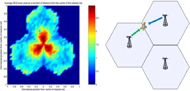
About the throughput enhancement, in the traditional IEEE802.16e the radio signal is approximate a “concentric circles”, near the base station will get better modulation and coding schemes (MCS), far side of the base station will get the poor. The sketch maps are as Figure 2-3. If we setup some relay station (RS) around the base station, the more relay stations (RS) will get better modulation and coding schemes (MCS). The diagram is Figure 2-4.
Figure 2-3 IEEE 802.16e Figure 2-4 IEEE802.16j
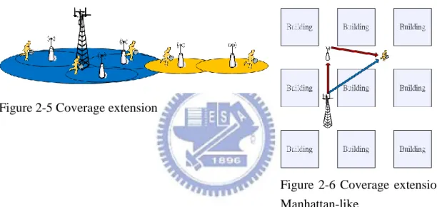
About the coverage extension, if user is in the city outskirts like Figure 2-5, after consider the Operating expenditure (OPEX) unworthy to set a new base station, or in Manhattan-like environment, the radio signal will easy shadow by edifice, and the corner like the Figure 2-6. If set a relay station (RS) at the street corner or on the streetlamp, it might reduce the transmission power loss, and further it can realize the coverage extension.
Figure 2-5 Coverage extension
Figure 2-6 Coverage extension Manhattan-like
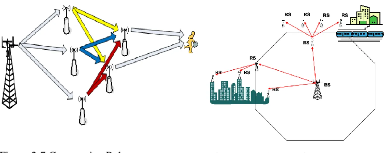
If the relay station (RS) quantity were increase, the system will become more complex. In system point of view, the total resource integrations need to be considered like frequency reuse [13],[14], Cooperative Relay[15],[16], and Relay station (RS) Grouping[17],[18], etc. The Cooperative Relay and Relay station (RS) Grouping diagram were show as Figure 2-7 and Figure 2-8.
Figure 2-7 Cooperative Relay Figure 2-8 RS Grouping
2.2.2
Relay Stations Usage
To obtain best possible performance in the network, character of RSs and their placement must be carefully chosen. Hence, IEEE 802.16's Relay Task Group are defined four kinds of RS usage model to obtain the high system performance [19][20]:(1) Fixed infrastructure usage model (2) In-building coverage usage model (3) Temporary coverage usage model (4) Coverage on mobile vehicle usage model
(1) Fixed infrastructure usage model
Fixed relay stations are utilized in this model that the owner is the infrastructure provider. The provider can be mounted on towers, poles, tops or sides of buildings, lamp posts, or in other locations. They can plan the locations of RS antennas to obtain LOS channels between the MMR-BS and RS, but this will not always be practical, so NLOS channel conditions on links between MMR-BS and RS can be expected.
(2) In-building coverage usage model
In this model RSs are deployed to provide better coverage and higher throughput in a building, tunnel or underground such as on a subway platform. There can be a single RS or multiple RSs that services a small or big building, tunnel, underground location. The RS can be owned by the infrastructure provider or by the customer, and the function can be fixed or nomadic.
Between MMR-BS and RSs the channel conditions will usually be NLOS, but the RS might have one or more antennas mounted to the outside of the building to provide the access link between itself and the upstream RS or MMR-BS and one or more antennas mounted inside the building to provide coverage to downstream RSs and users.
(3) Temporary coverage usage model
In this usage model the RS is deployed temporarily and nomadic to provide additional coverage or capacity in an area where the MMR-BS and fixed RS can not provide
sufficient coverage or capacity. In these situations in which temporary coverage is required in:
(a)Emergency / Disaster Recovery: The fixed infrastructure may have been destroyed. (b)Temporary Coverage for Event: In sporting game, military event or need fair requires that coverage provided for the duration of the event.
Typically, antenna heights are relatively low, such as vehicle-mounted masts, and need quick deployment and fast tear-down due to unanticipated environmental anomalies or deployment dynamics. The channel conditions between MMR-BS and RSs can be expected LOS or NLOS.
(4) Coverage on mobile vehicle usage model
In this usage model coverage is provided for user devices which are moving together on a mobile vehicle, such as a bus, a train or ferries. A mobile RS is fixed in the vehicle and it connects to an MMR-BS or RS through a mobile link. Then the RS provides a fixed access link to MS/SS devices. RSs deployed in this usage model are expected to be complex. Antenna heights would be significantly lower then the fixed and nomadic deployments due to vehicular restrictions and operational safety concerns. Mobile relay in this model may have severe size, weight, and power limitations.
2.3 Overview of the Physical Layer
In traditional network, the Base Station and User Terminal were connection by wireless, then that was the “single-hop” network. The relay technology is between the Base Station and User Terminal will insert one or more Relay Station (RS). That mean the wireless signal will through “Two-hop” or “Multi-hop” to the User Terminal.
The operation frequency of IEEE802.16d standard [1] is distributed from 10-66GHz, which is line of sight (LOS) transmission, or 2-11GHz, which is non line of sight (NLOS) transmission. In the urban area, line of sight transmission is almost impossible due to the prevention of buildings. So to solve problems will focus on 2-11GHz PHY. There are three air interface defined in spec:
(1)WirelessMAN-SCa
This model uses a single-carrier modulated air interface. (2)WirelessMAN-OFDM
It is a 256 carrier orthogonal frequency division multiplexing scheme. Multiple access mechanism is time division multiple accesses based.
It uses orthogonal frequency division multiple access. Multiple accesses are provided by assigning a subset of the carriers to specific user. In 802.16e standard, the number of subcarriers could be 128, 512, 1024, and 2048. The standard supports two duplex methods: time division duplex (TDD) and frequency division duplex (FDD). In 802.16j the standard need to fit in with backward compatible.
In this thesis, the research adopts OFDMA PHY and TDD mode. So in the latter part, the introduction of this system will be focused on the OFDMA PHY, and the model of Relay Station (RS) operation, scheduling, frame structure, these can separate two part, one is “Transparent mode”, another is “Non-Transparent mode”.
2.3.1
Relay Station to operation model
Here have two kinds of relay operations: transparent relay (Figure 2-9) and non-transparent relay (Figure 2-10). RS shall work in one mode at one time. The relay operation mode can be configured during it’s network entry or network deployment [21].
Figure 2-9 Transparent Relay Figure 2-10 Non-Transparent Relay
2.3.1.1 Transparent Relay
The operations, scheduling mode, frame structure of the characteristics of transparent Relay Station will be described in the following session.
2.3.1.1.1 Operation
In transparent relay operation, MS associated with RS which is located in the coverage of Multihop relay base station (MR-BS), and the DL control signal from MR-BS can directly transmit to MS without RS relaying. MS will not recognize the existing of the RS even though MS communicates with the MR-BS via the transparent RS. Transparent Relay will be used to improve the poor radio link in the cell edge, coverage hole, dead spot, but it will not to extend the coverage as shown in Figure 2-9.
The total resource was controlled by the MR-BS. In this mode, the relay station (RS) got the radio signal from the Multihop relay base station (MR-BS), and it will estimate the channel condition of user terminal or the subordinate relay station(RS), and re-transmit it by appropriate modulation and coding schemes (MCS).
2.3.1.1.2 Scheduling
Transparent relay only supports centralized scheduling, and transparent relay is dedicated for throughput enhancement, where MS is located in the coverage of BS’s broadcast information.
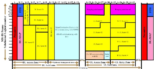
2.3.1.1.3 PHY Frame Structure
In the frame structure(Figure 2-11), Multihop relay base station (MR-BS) have it own transmit DL frame-start preamble, FCH, MAP messages or channel descriptor (DCD/UCD) messages, but Relay Station (RS) did not have. All MSs and RSs within one MR-cell are synchronized to MR-BS by its preamble, and get the resources allocations by DL/UL MAP.
Preamble: In the first symbol of frame structure is occupied by the preamble. The
function of preamble is used for the synchronization and enables MSs to estimate the channel condition and correct frequency/time offset.
Frame Control Header (FCH): It consists of the DL_Frame Prefix, and specifies the
length of the DL_MAP message that immediately follows the DL_frame_Prefix and the repetition coding used for the DL-Map message.
DL-MAP and UL-MAP: They completely describe the contents of the DL and UL
subframe. The DL-MAP and UL-MAP allocate the resource for DL and UL data bursts, which include what bursts belong to MS. Besides, modulation and coding schemes (MCS) per burst are indicated by the Downlink Interval Usage Code (DIUC) and Uplink Interval Usage Code (UIUC). In the UL-MAP, it also grants bandwidth to specific MSs. Therefore, MSs can transmit data in their assigned uplink allocation. The DL and UL bursts are use for data transmission of different users.
Ranging subchannels are dynamically allocated by the MAC layer and indicated in
the UL-MAP. The ranging subchannel has three major functions: (a) Initial ranging: It is used by any MS when it wants to synchronize to the system channel for the first time. (b) Periodic-ranging: It is used for periodically updating system time and power. (c) Bandwidth request: It is used for requesting uplink allocations from the BS.
Transmit/receive transion gap (TTG) is a gap between the downlink burst and the
subsequent uplink burst. It gives the time for the BS switches the state of transmit to receive mode and MSs to switch from receive to transmit mode.
RS transmit/receive transition gap (R-TTG) is the minimum transmit to receive
the transmitted burst to the first sample of the received burst at the antenna port of the RS.
Receive/transmit transition gap (RTG) is a gap between the uplink burst and
subsequent downlink burst. It allowed the time for the BS to switch the state of receive to transmit mode and MSs to switch from transmit to receive mode.
RS receive/transmit transition gap (R-RTG) is minimum receive to transmit
turnaround gap required at an RS. It is measured from the time of the last sample of the received burst to the first sample of the transmitted burst at the antenna port of the RS.
DL access zone: A segment of the DL sub-frame in the MR-BS/RS frame used for
MR-BS/RS to MS or transparent RS transmission. The DL access zone may consist of the entire downlink subframe, depending on the method used to separate the transmissions on the access and relay links.
DL relay zone: A segment of the DL sub-frame in the MR-BS/RS frame used for
MR-BS/RS to RS transmission. A frame may have no DL relay zone, depending on the method used to separate the transmissions on the access and relay links.
UL access zone: A segment of the UL sub-frame in the MR-BS/RS frame used for
MS to MR-BS/RS transmission. A frame may have no UL access zone, or the UL access zone may consist of the entire uplink subframe, depending on the method used to separate the transmissions on the access and relay links.
UL relay zone: A segment of the UL sub-frame in the MR-BS/RS frame used for RS
to MR-BS/RS transmission. A frame may have no UL relay zone, or the UL relay zone may consist of the entire uplink subframe, depending on the method used to separate the transmissions on the access and relay links.
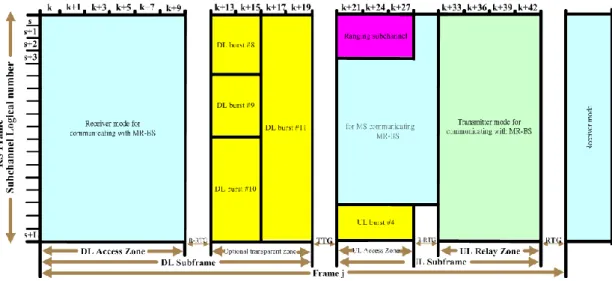
Figure 2-12 RS frame structure configurations for a transparent relay station
2.3.1.2 Non-Transparent Relay Operation
The operations, scheduling mode, frame structure of the characteristics of non-transparent Relay Station will be described in the following session.
2.3.1.2.1 Operation
Non-transparent Relay is to increase the cell coverage (Figure 2-10). In this mode the non-transparent relay station (RS) can allocate the partial resource to the user terminal or the subordinate relay station (RS). All data and control signal transmission between MR-BS and MS are relayed. It can reduce the Multihop relay base station (MR-BS) loading and optimize the system performance, but Non-transparent Relay will be more complex then Transparent Relay. Transparent RS and non-transparent RS can coexist in one MR-cell.
2.3.1.2.2 Scheduler
The non-transparent RS may support centralized scheduling or distributed scheduling. The centralized scheduling RS does not create its own DL/UL MAP but may modify the MAP from MR-BS if necessary. As a contrast, the distributed scheduling RS generates its own DL/UL MAP.
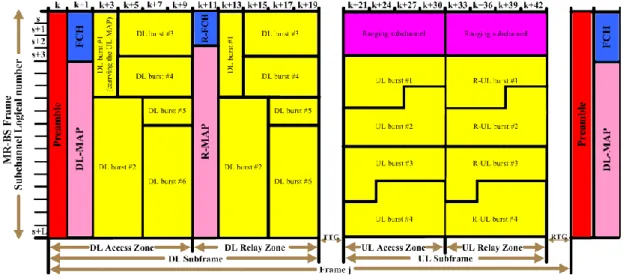
2.3.1.2.3 PHY Frame Structure
The Multihop relay base station (MR-BS) and the non-transparent relay station (RS) transmit it own frame messages (Figure 2-13, Figure 2-14). When the non-transparent RS used centralized scheduler; the MR-BS will determine the transmission parameters and allocation for DL/UL access zone and relay zone of MR-BS and RS frame.
The transmission parameters and allocation information include FCH, DL/UL MAP for access zone, R-FCH, R-MAP and for relay zone, the access zone and relay zone was belonged to the frame of MR-BS. The first transmitted relay zone in the downlink shall include an R-FCH and an R-MAP. When non-transparent RS receives these transmission parameters and allocation information, RS shall transmit FCH, DL/UL MAP in DL access zone, and the RS forward the scheduling information for other RSs in the relay path in DL relay zone the function like the MR-BS. Other intermediate RSs shall do the same operation as the first RS. And the access RS only broadcasts FCH, DL/UL MAP in DL access zone as indicated by the received scheduling information from super ordinate RS or MR-BS.
The MR-BS has to do the scheduling for non-transparent RS with centralized scheduler. In every frame duration time, RS needs to schedule MAP message which contains all the scheduling and configuration information, it had a very large overhead.
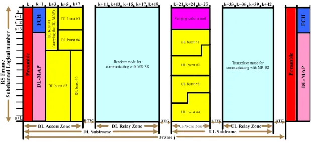
Figure 2-14 RS frame structure configurations for a non-transparent relay station
2.3.2
PHY Slot and Data Mapping
The OFDMA slot is a minimum unit for system data transmissions. One OFDMA slot occupies one subchannel and several OFDMA sysmols. Here has four subchannel allocation performed in the following ways:
(a) Downlink Full Usage of Subcarriers (FUSC) using the distributed subcarrier permutation, one slot is one subchannel by one OFDMA symbol.
(b) Downlink Partial Usage of Subcarriers (PUSC) using the distributed subcarrier permutation, one slot is one subchannel by two OFDMA symbols.
(c) Uplink PUSC using either of the distributed subcarrier permutations, one slot is one subchannel by three OFDMA symbols.
(d) Uplink and Downlink Band Adaptive modulation and coding (Band AMC) using the adjacent subcarrier permutation. One slot is one subchannel by one, two, three, or six OFDMA symbols.
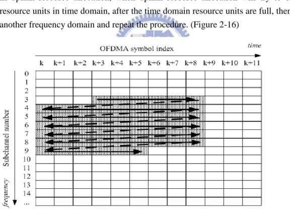
All the allocation refers to logical subchannels. A data region is a two-dimensional allocation which contents a group of contiguous subchannels and OFDMA symbols. The minimum unit of data mapping is an OFDMA slot. Based on standard, how many resource units would be assigned to a transmission is decided by BS and the mechanism is different in downlink and uplink transmission. In downlink resource allocation, system will consider the data size and try to enforce the resource units first in frequency domain. After the frequency domain is enforced, then it goes to the next time domain to enforce resource units. (Figure 2-15)
Figure 2-15 OFDMA slots to subchannels and symbols in the downlink PUSC mode In uplink resource allocation, when uplink resource allocation will try to enforce resource units in time domain, after the time domain resource units are full, then go to another frequency domain and repeat the procedure. (Figure 2-16)
Figure 2-16 OFDMA slots to subchannels and symbols in the uplink PUSC mode
2.3.3
Subcarrier Permutation
Subcarrier permutation is a method to assign frequency subcarriers into subchannels. The allocation of subcarriers to subchannels is accomplished via permutation rule. There are two kinds of permutation modes:
(a)Distributed subcarrier permutation: The subcarriers belonged to a subchannel are selected pseudo randomly from all subcarriers. It can average inter-cell interference and avoid fading effect.
(b)Adjacent subcarrier permutation: The subchannel whose subcarriers coming from adjacent subcarriers. In this method, system can take advantage of frequency select fading and get multiuser diversity form frequency domain.
IEEE802.16 standard provides three ways to group subcarriers into subchannels: (a)Full Usage of Subchannels (FUSC)
This method is only used in downlink and can use all subcarriers to do permutation for one subchannel. It can achieve the best frequency diversity by spreading subcarriers over entire band.
(b)Partial Usage of Subchannels (PUSC)
This method can be used both in downlink and uplink. It will group subcarriers first then choose subcarriers per group and each group only provides one subcarriers to form a subchannel.
(c)Band Adaptive Modulation and Coding (Band AMC)
This method can be used both in downlink and uplink. It uses adjacent permutation mode. The bandwidth is divided into sub-band and tries to utilize the frequency select fading to enhance system performance.
2.3.4
Adaptive Modulation and Coding (AMC)
IEEE802.16e system is able to adjust modulation coding scheme depends on the carrier to interference plus noise ratio (CINR) condition of the radio link. IEEE802.16 OFDMA architecture supports multiple modulation methods: Quadrature Phase Shift Keying (QPSK), 16-state Quadrature Amplitude modulation (16-QAM), and 64-state Quadrature Amplitude modulation (64-QAM). It can adjust dynamically to trade off the efficiency and the robustness. The OFDMA architecture can support several coding schemes, like Convolution Code (CC), Convolution Turbo Code (CTC), Low Density Parity Check Code (LDPC), and Block Turbo Code (BTC).
2.3.5
Relaying techniques
In relaying technique, the signal goes through a single multi-hop path formed by relays between the source and destination. About the relaying technique, there are four possible technologies:
(a)Amplify and Forward (AF) (b)Decode and Forward (DF) (c)Compress and Forward (CF) [22] (d)Estimating and forwarding (EF) [23]
(a)Amplify and Forward (A&F): The function is like the analog repeaters; relay will amplify the signal and retransmits it to the destination. The signal might aggregate of relay link fading and additive receiver noise. The degraded signal and noise are amplified and forwarded, thereby increasing the system noise level.
(b)Decode and Forward (D&F): The function is like the digital repeaters (or call layer 2 relays). The relay demodulates and decodes the received signal before forwarding it to the destination.
(c)Compress-and-Forward (C&F): It also known as Quantize and Forward Q&F [24]. C&F is the relay quantizes the signal when it received from the source and encodes the samples into a new packet which is forwarded to the destination, so that the latter can combine the two observations.
(d)Estimating and forwarding (E&F): The relay does not decode the input data, but it re-encodes the received signal (after quantization) and transmits it to the destination. In this case the forwarded signal contains possible estimation errors. The destination uses the relay estimation as side information when coding the actual direct link signal. The most popular of relaying techniques is decoded and forward (D&F). In [25][26], the performance analysis was show the decoded and forward (D&F) techniques have the better bit error rate (BER) then Amplify and Forward (A&F) in same SINR (Signal to Interference plus Noise Ratio).
2.4 Overview of the Medium Address Control Layer
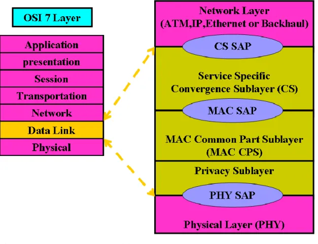
In Open Systems Interconnection Basic Reference Model (OSI Reference Model or OSI Model), the Data Link Layer can separate two sublayers: Media Access Control (MAC) and Logical Link Control (LLC). The MAC layer connects with the Physical layer and manages the interaction of devices with a shared medium. Above MAC Layer and under Network Layer is the LLC sublayer, which deals with addressing and multiplexing on multi-access media.
The MAC layer of the system will process several tasks, and keep the system efficient. IEEE802.16 was designed for point to multipoint (PMP) broadband wireless access applications and is a connection-oriented system. It is designed to meet the needs of the very high date rate application with a variety of quality of service (QoS) requirement on both uplink and downlink. The MAC layer must manage the radio resource to decide how to let users access the resource, handoff users when they are going to leave the cell coverage, decides whether to let users register into the system, to do power control or rate control, etc. The MAC layer protocol is flexible and efficient over a wide range of different data traffic models. The radio resource management is an important issue should be done to maintain the QoS requirement
which is also implemented in this layer. The MAC layer must integrate the information from upper layer and Physical layer. It should know the traffic QoS requirement to allocate suitable resource to users. It will do retransmission if Physical reflects there is error occurs before the transmission. It should fragment and packet the data unit to avoid transmission error occurs or transmission inefficient.
2.4.1
802.16e MAC structure
In IEEE802.16 system, the MAC layer is divided into three sublayer and all of them have their own functionality as show in figure2-17.
Figure 2-17 IEEE 802.16 protocol layer
(a) Service-Specific Convergence Sublayer (CS)
This sublayer is an interface between upper layer and MAC layer. It will identify different traffic from upper layer and assign connection ID (CID) to each connection and classify service data units (SDUs) to the proper MAC connection. It also provides payload header suppression and reconstruction to enhance the air link efficiency. (b) Common Part Sublayer (CPS)
The Common Part sublayer manages the main function of controlling the whole radio resource. It was about the QoS control, fragmentation and packing, scheduling, request-and-grant, admission control, handover, and ARQ will be controlled in this sublayer. Besides, segmentation of SDU into MAC PDU (protocol data unit) is also implemented in this sublayer.
(c) Security Sublayer
In multihop relay system, RS uses the same security architecture and procedures as an SS to provide privacy, like the authentication of network access, registration, key exchange, and encryption of PDUs and confidentiality between itself and the MR-BS. MR-BS and a group of RSs in MR cell maintain a set of trusted relationships, called Security Zone, in order to satisfy requirements of multi-hop relay system operation.
2.4.2
MAC PDU Formats
The MAC PDU is a data exchanged unit between the MAC layer of the BS and MSs. The maximum length of the MAC PDU is 2048 bytes, including header, payload, and CRC. A MAC PDU consists of a 48bit MAC header, a variable length data payload, and an optional 32 bits Cyclic Redundancy Check (CRC). There are two types of MAC headers: Generic MAC header and Bandwidth request MAC header. The MAC PDUs include some subheaders. Here was the MAC PDU subheader:1. Grant management subheader. 2. Fragmentation subheader. 3. Packing subheader. These MAC subheaders include the bandwidth request, uplink transmit power report, CINR report, CQICH allocation request, PHY channel report, uplink sleep control, SN report, and feedback functionalities, etc.
2.4.3
Fragmentation and Packing
In 802.16e system, MAC SDUs coming from Service-Specific Convergence Sublayer(CS) will be formatted according to the MAC PDU format in the Common Part Sublayer (CPS), possibly with fragmentation and packing. The fragmentation and packing process can utilize the bandwidth allocation more efficiently.
The fragmentation subheader indicates the presence and orientation in the payload of any fragments of SDUs. The process divided a SDU into different PDUs payload areas, because the maximum MAC PDU size is limited in 2048 bytes, and larger PDU size may causes error occurs more easily. Therefore, divide SDU properly according to the channel condition will avoid transmission errors and save the resource. Figure 2-18 shows the process of fragmentation.
Figure 2-18 Fragmentation
The packing subheader is used to indicate the packing of multiple SDUs into a single PDU. Packing process is to pack several SDUs into a single PDU payload. In this way, system may avoid resource waste due to the overhead caused by MAC header and CRC. Figure 2-19 shows the process of packing. Both processes may be initiated by either a BS for a downlink connection or a MS for and uplink connection.
Figure 2-19 Packing
2.4.4
ARQ
In [1][2][21][27], the Automatic Retransmission request (ARQ) can request the retransmission of part of a SDU. The ARQ mechanism is a part of the MAC, which is an optional function. A connection can not have a mixture of ARQ and non-ARQ traffic, and the ARQ mechanism is limited to one unidirectional connection. A MAC SDU is logically partitioned into ARQ blocks whose length is specified by the connection TLV (type/length/value) parameter, “ARQ_BLOCK_SIZE” and MAC PDU which is formatted by integer number of ARQ blocks is shown in Figure2-20.
Figure 2-20 Two consecutive SDUs presented to MAC for the same connection Once an SDU is partitioned into a set of blocks, partitioning remains in effect until all blocks of the SDU are successfully delivered to the receiver, or the SDU is discarded by the transmitter state machine. The receiver sends acknowledgement (ACK) or negative acknowledgement (NAK) messages to indicate the transmitter which ARQ
block of the PDUs have successfully been received or which have been lost. For instance, if the Figure2-21 PDU#1 was successfully delivered, but the PDU#2 was fail by transmission. The ARQ consist of two mechanisms, which is (a) With rearrangements and (b) Without rearrangements of blocks.
Figure 2-21 Original transmission
(a)With rearrangement, if the ARQ blocks of one PDU need to be retransmitted, it will be divided into different PDUs which share the blocks like the Figure2-22 can be change to two retransmitted PDUs .
(b)Without rearrangements, if any block of one PDU need to be retransmitted, the transmitter will retransmit all ARQ block of this PDU like the Figure2-23.
Figure 2-22 Retransmission of PDU #2 with rearrangement
Figure 2-23 Retransmission of PDU #2 without rearrangement
In the Mobile Multihop Relay System (MMR), the ARQ mechanisms were consisting of three modes: (1) End-to-End ARQ mode. (2) Two-link ARQ mode. (3) Hop-by-Hop ARQ mode.
(1) End-to-end ARQ mode: The ARQ operation is performed between an MR-BS and an MS, which is same as original IEEE802.16d/e. An RS doesn't have an additional ARQ functionality.
(2) Two-link ARQ mode: The ARQ operation is divided into two links. Performed both between relay link (MR-BS and access RS) and between access link (RS and MS). The MR-BS schedules retransmission to access relay station when ARQ block or TDU (tunnel data unit) is corrupted in the relay link. The RS schedules retransmission to MS when ARQ block is corrupted in the access link. When an intermediate RS exists between MR-BS and access RS, it just forwards the ARQ block and ARQ feedback information between MR-BS and access RS. ARQ operation between access RS and MS is same as original IEEE802.16d/e.
(3) Hop-by-hop ARQ mode: Performed between each adjacent station and the intermediate RSs are involved in the ARQ operation. Two adjacent stations could be MR-BS, RS or MS. The support of ARQ mode is performed during the RS network entry. ARQ operation between access RS and MS is same as original IEEE802.16d/e. When TDU is corrupted in the relay link, the subordinate RS sends back R-NAK, and the MR-BS/super-ordinate RS schedules the retransmission of TDU to the subordinate RS. Then the MR-BS receives R-ACK from the subordinate RS, it waits for an ACK from the MS relayed by the intermediate RSs. Access RS may modify the ARQ feedback IE received from MS to indicate the ACK information to MR-BS. After MR-BS receives ACK from MS or super-ordinate RS receives R-ACK from the sub-ordinate RS, it clears the buffer corresponding to ARQ blocks. For superordinate RS, it clears the buffer corresponding to TDU after receiving R-ACK from the sub-ordinate RS.
Two-link ARQ is applicable in both tunnel and non-tunnel based forwarding while hop-by-hop ARQ is applicable in only tunnel-based forwarding mode. These modes are supported when RS is enabling on distributed scheduling mode with distributed security.
In [21][27], the Hybrid Automatic Repeat request (HARQ) scheme is an optional function of the MAC and can be enabled on a per-terminal basis. A burst can not have a mixture of HARQ and non-HARQ traffic. There are many variations on retransmission methods for HARQ, the most popular of HARQ are (1) Incremental Redundancy (IR) (2) Chase Combining.
(1)IR: The PHY layer will encode the HARQ packet to generate several versions of encoded subpackets. Each subpacket shall be uniquely identified by using a subpacket identifier (SPID).
(2)Chase Combining: The PHY layer shall encode the HARQ packet generating only one version of the encoded packet. As a result, no SPID is required for Chase Combining.
For downlink HARQ operation, the BS will send a version of the encoded HARQ packet. The SS will attempt to decode the encoded packet on this first HARQ attempt.
If the decoding succeeds, the SS will send an ACK to the BS, but if the decoding fails, the SS will send a NAK to the BS. In response, the BS will send another HARQ attempt. The BS may continue to send HARQ attempts until the SS successfully decodes the packet and sends an acknowledgement.
Two implementations of HARQ are supported: (1) Per-terminal: HARQ is enabled for all active CIDs for a terminal, and (2) Per-connection: it can be enabled on a per CID basis by using the DSA/DSC messages. The two implementation methods shall not be employed simultaneously on any terminal. If HARQ is supported, the SS shall support per-terminal implementation, and the MS shall support per-connection implementation. One or more MAC PDUs can be concatenated and an HARQ packet formed by adding a CRC to the PHY burst.
The HARQ mechanisms are describe in [28][29][30] for the Mobile Multihop Relay System (MMR). In [28][29], it have the elementary architecture, which discloses the HARQ category, and how to reuse the Channel Quality Indicator Channel (CQICH) indexed. In [30], it was defined that the main HARQ architecture which in the Transparent mode and Non-Transparent mode.
2.4.5
QoS based service classes
The IEEE802.16 provides several Quality of Service (QoS) classes for system supports different kinds of service. For different classes, system sets different parameters and transmission/request methods to let system maintain the QoS requirement for different kinds of service [31].
In downlink, it has four kinds of QoS classes: (a)Real-time CBR data streams
The service is designed to support real-time service flows that generate fixed-size data packets on a periodic basis, such as T1/E1 and VoIP without silence suppression. (b)Real-time VBR data streams
The service is designed to support real-time service flows that generate variable size data packets on a periodic basis, such as moving pictures experts group (MPEG) video.
(c)Delay-tolerant VBR data streams
The service is designed to support delay-tolerant data streams consisting of variable-sized data packets for which a minimum data rate is required, such as FTP. (d)Best effort data streams
The service is designed to support data streams for which no minimum service level is required and therefore may be handled on a space-available basis.
In uplink, it has five kinds of QoS classes. (a)Unsolicited Grant Service (UGS)
The UGS is designed to support real-time service flows that generate fixed-size data packets on a periodic basis, such as T1/E1 and VoIP without silence suppression. (b)Real-time Polling Service (rtPS)
The rtPS is designed to support real-time service flows that generate variable size data packets on a periodic basis, such as moving pictures experts group (MPEG) video. (c)Extended Real-time Polling Service (ertPS)
Extended rtPS is a scheduling mechanism which builds on the efficiency of both UGS and rtPS. The Extended rtPS is designed to support real-time service flows that generate variable size data packets on a periodic basis, such as Voice over IP services with silence suppression.
(d)Non-real-time Polling Service (nrtPS)
The nrtPS is designed for non-real-time service which can tolerate more delay, such as FTP, web-browsing, etc.
(e)Best Effort Service (BE)
BE service is with the lowest QoS level. These kinds of service are designed to support data streams for which no minimum service level is required and therefore may be handled on a space-available basis.
2.4.6
Request and Grant Mechanism
The request and grant mechanism for different QoS classes will be different, this is because the characteristics and requirement are different.
In downlink, it is much easier to handle these procedures, because the BS has the precise information about traffic requirement. Therefore, BS can easily give bandwidth to downlink traffic. It’s no need to do request and grant.
In uplink, it is more complicated to do request and grant. Requests refer to the mechanism that MS uses to indicate BS that they need uplink bandwidth allocation. The bandwidth request message may be transmitted during any uplink allocation, except initial ranging interval. A transmitted bandwidth request header will indicate the size of opportunities to be requested. The bandwidth request message could be transmit through polling mechanism. Polling is the process that the BS allocates to the MS bandwidth specifically for the purpose of bandwidth requests. After BS receives bandwidth request message, if there is additional bandwidth, BS will grant corresponding bandwidth to MS based on their request.
2.4.7
Handover
Handover mechanism handles mobile station switching from one base station to another. There are two basic types: soft handover and hard handover.
In soft handover, it is used in voice-centric cellular networks such as GSM or CDMA system. It uses a make-before-break approach whereas a connection to the target BS is
established before a MS leaves an ongoing connection to a BS. When used for non-real-time data traffic (Hypertext Transmission Protocol, File Transfer Protocol), soft handover will result in lower spectral efficiency because this type of traffic is burst and does not require continues handover from one BS to another.
In hard handover, connectivity with a BS is ended first before MS switches to another BS. This is a break-before-make approach. Hard handover is more bandwidth efficient than soft handover, but it causes longer delay.
In Relay system, there are two handover scenarios: (1) Intra- virtual cell (VC) handover: In Intra-VC handover, MS will not be aware the mechanism so the mechanism can be performed by resource allocation procedure. (2) Inter- virtual cell (VC) handover: Inter-VC handover procedure needs to communicate with MR-BS to another. Therefore, the MS will be aware the process. In the implementation complexity and the backward compatibility points of view, decentralized intra-VC handover and centralized inter-VC handover would be a preferred handover solution for 802.16j [32].
CHAPTER 3
SIMULATION SETUP
In this chapter, the IEEE 802.16j system level simulation platform will be described. The details of system architecture and simulation parameters are going to be explained. Then, the Link Budget, such as path loss and shadow fading, is set to be referred for IEEE 802.16j standard. The basic radio resource management (RRM) is mentioned in this chapter, such as Adaptive Modulation and Coding (AMC), scheduling controls, handoff method, and the traffic models of simulation is showed in this chapter. Finally, simulation architecture is also introduced.
3.1 The architecture of mobility platform
In the simulation of a mobile relay system, interference is an important element that determines performance in real cellular system. The interference effects need to be considered into the simulation. Now building a multi-cell environment in the simulation platform in which the inter-cell interferences can be considered into the performance analysis. Hence, consider the two tier interference per cell, and there are nineteen cells in the platform in order to approximate the real cell coverage with a hexagon. The system structure in Figure 3-1, we can see only center cell have two tier interference cells, as the result, consider the wrap around BSs architecture (Figure 3-2) to meet the requirement of interference calculation. After wrap around, the statistic simulation result of nineteen cells will be more meaningful.
Figure 3-2 Example of Wrap around
The cell radius is set to 1 km [32]. This approximate cell coverage is a result from a plan of link budget. The total cell bandwidth is set to 10 MHz [1]. In the simulation platform, the three sectors per cell are adopted (Figure 3-3). In each sector, it has the different antenna direction and a regular pattern of deployment.
Figure 3-3 Example of sector deployment
In the simulation platform, the distance between the base station and relay station was 2/3 cell radius, and the angle between the two relay stations was used circumferential angle over the amount of relay stations. For example, the three relay stations deployment scheme were followed the base station antenna direction of the sector (Figure 3-4). The six relay stations deployment scheme were placed in the medium of the base station antenna direction and base station sector boundary (Figure 3-5). Regarding another number of relay stations like four, five, seven, eight, etc, those are
unfairness placement in sector’s point of view. As a result of the issue, the placement scheme we only focused on three, six and nine relay stations.
Figure 3-4 Example of 3RSs deployment.
Figure 3-5 Example of 6RSs deployment.
Reuse factor 1 can be used in this simulation, and the deployment for reuse factor 1 is shown as Figure 3-6. If reuse factor 3 (Figure 3-6) was adopted, the total system bandwidth is three times of the reuse factor 1. Therefore, the total system bandwidth of reuse factor 3 is equal to 30 MHz.
Figure 3-6 Cell plane for reuse factor 1 and 3
The setting of the antenna pattern is referred to 3GPP’s model [33] as following.
2 3 ( ) = m in 12 , m , w here -180 180 dB A A (3-1)
For 3 sector case: 120∘ antenna pattern, θ3dB is 70∘ , Am is 20 dB, and bore-sight
gain is 3 dB, where θ3dB is the Azimuth radian in which the antenna pattern gain is
3dB loss, Am is maximum loss compared with maximum antenna pattern gain, and
bore-sight gain is the maximum antenna pattern gain on the direction of antenna bore-sight.
The sector and relay stations architecture in IEEE802.16e/j system can reduce the transmission power of BS/RS antenna and inter-cell interference. The total bandwidth of a cell is divided equally into three parts, as the result, the intra-cell interference for sectors and relay stations are not need to be considered. But it still has a small part of inter-cell interference in different sectors and relay stations of distinct BSs caused by subcarrier permutation. This characteristic is very difficult to simulate, so the platform was assume a sector or relay station would produce interference to other sectors or relay station which have the same direction.
3.2 The architecture of frame transmission
In this thesis, the performance analysis focus on the downlink and it apply to OFDMA on PHY layer with TDD mode. The IEEE802.16j can support asymmetric access zone and relay zone in downlink and uplink transmission of TDD mode for which the system can adjust the ratio according to the traffic loading of downlink and uplink transmission.
The frame length in the simulation is set to 5 ms, and the frame structure we used is 1024-FFT OFDMA downlink carrier allocations – PUSC mode defined in the standard [1]. The carrier distribution is shown in Table 3-1. In the 1024 subcarriers, only 720 subcarriers carry data information and other subcarriers are used for guard band, pilot and DC subcarrier.
Table 3-1 1024-FFT OFDMA downlink carrier allocations with PUSC
Subcarrier types Number Total subcarriers 1024
DC subcarriers 1
Guard subcarriers 92 (Left), 91 (Right) Sub-channels 30
Data sub-carriers within each sub-channel 24
The symbol length and the number of OFDMA symbols are define in WiMAX Forum [34][35]. In 10MHz bandwidth and 1024 FFT size, the symbol period should be 102.9 μs and there will be 48 OFDMA symbols per frame. In our simulation, we assume it has the different ratio of downlink and uplink. It means that if we take off the overhead control message that included Preamble, FCH, Downlink map, Uplink map,
and we use PUSC, one slot is consisted of two/three symbols in downlink/uplink. As the result, 24 OFDMA symbols are assigned to downlink subframe, 18 OFDMA symbols are assigned to uplink subframe, 5 OFDMA symbols are assigned to the control message, and the lest one is assigned to the TTG. Therefore, the resources will have 12 OFDMA slots for data transmission in every downlink subframe, and 10 subchannels per sector (30 subchannels /3 sector = 10).
To reduce the complexity of implement platform, we assume R-RTG (RS receive/transmit transition gap) was zero, that is signify that the base station can transmit the data to the relay station in the R-RTG. In the 12 OFDMA slots, we will divide two parts: 7 OFDMA slots for access zone, 5 OFDMA slots for relay zone. Hence, there will be 70 resource units per frame per sector (3 sector model) and 50 resource units per frame per relay station (3RSs model) to transmit data and messages. In 6 relay stations, it will allocate the half resources, which are 25 resource units per frame per relay station.
3.3 Link budge
The link budget settings of downlink transmission in our simulation are as far as possible to match the IEEE 802.16e/j real environment.
3.3.1
Antenna parameter
In [32] [33][36], it makes deployments scenario assumptions for 802.16e/j, like Table 3-2. In our simulation we adopt the outdoor vehicular scenario, which the BS transmitted power is 46 dBm, the BS antenna gain is 17 dBi, the MS antenna gain is 3dBi on downlink transmission.
About the relay station setup, it was fix deploy in the simulation, so we adopt the outdoor to indoor condition, that is transmitted power is 36 dBm, the antenna gain is 17 dBi. And in IEEE802.16j Evaluation Methodology [36], the channel models need to consider the antenna height, like the BS antenna height is 30m, the RS antenna height is 15m. About the MS antenna height is 1.5m which was defined in [36]. The BS back off which is used to avoid the RF circuit working in the non-linear region due to the peak to average power ratio (PAPR) of OFDM system is 5dB. The common usage value of thermal noise density is -173.93dB/Hz[37]. The receiver noise figure of MS is 9dB [38].
Table 3-2 Link Budget Parameter of 802.16e/j system
Indoor Outdoor to indoor Outdoor vehicular BS Transmit power 27 dBm (0.5 W) 36 dBm (4 W) 46 dBm (40 W) MS Transmit power 17 dBm 17 dBm 27 dBm
BS antenna gain 6 dBi 17 dBi 17 dBi MS antenna gain 0 dBi 0 dBi 3 dBi BS antenna height 15 m 30 m
3.3.2
Fading effect
In wireless channel, the transmitted signal will suffer the fading issue which might significantly cause distortion to the signal. The fading effect can be categorized into three types: path-loss, shadow fading, and fast fading (multi-path and Doppler effects). Path-loss and shadow fading are large scale fading, and fast fading belongs to small scale fading. In the simulation, we only consider the large scale fading: Path-loss and Shadow fading. The fast fading will be in the future works.
3.3.2.1 Path loss
The path-loss mode is relative to the distance between transmitter and receiver. The increasing distance will cause the more attenuation of transmitted signal strength. In IEEE802.16j Evaluation Methodology [36], it provides several path-loss models as Table 3-3, and Table 3-4. In the simulation, the cell radius is 1km and the signal transmission in 2~11 GHz is non-line of sight (NLOS), and we also need to consider the relay station antenna placement in ART (Above Roof Top) or BRT (Below Roof Top). For this reason, we choose the two scenarios adopted in our simulation.
In BS to RS link is Type-D: Macro-cell suburban, ART to ART, LOS. In BS to MS link and RS to MS link are Type-E: Macro-cell, urban, ART to BRT, NLOS.
TABLE 3-3 SUMMARY TABLE OF PATH-LOSS AND SHADOW FADING STANDARD DEV TYPES FOR IEEE802.16J RELAY SYSTEM
TABLE 3-4 RELATIONSHIP BETWEEN PATH-LOSS AND USAGE MODELS
Here, the usage models were already described in section 2.2.2 Relay Stations to Usage, those are:
Ⅰ. Fixed Infrastructure Usage Model Ⅱ. In-Building Coverage Usage Model Ⅲ. Temporary Coverage Usage Model
Ⅳ. Coverage on Mobile Vehicle Usage Model
3.3.2.2 Shadow fading
The main reason for shadow fading is from the shelters situation in which there might be buildings, shelters, mountains on the transmission path. According to the test result of the real wireless environment, we could know the variance of shadow fading is a log-normal distribution statistically. The standard deviation of this distribution is