Improving Wireless Packet Throughput Using Hybrid-I1 ARQ
and Physical Layer Side Information
infomution
Cheing-hong Lin and Jingshown Wu
Room 519
Department of Electrical Engineering and Graduate Institute of Communication Engineering
National Taiwan University Taipei, Taiwan 106 17
R.0.C
high-rate c&
Abstract
-
In this paper, the physical layer side information isemployed to improve the throughput of the hybrid-I1 ARQ
protocol in the binary phase shift keying wireless communication
system. With the combination of the hybrid-I1 ARQ and the
n-bit-marked error correction scheme, the packet throughput is
improved significantly. The numerical examples show that the
throughput of this combination scheme may have a maximum
gain about 0.26.
I. INTRODUTION
Wireless communications possess the convenient mobility property, which is very desirable. However, the air link, which may be effected by noise, multi-path fading, Doppler frequency shift, introduces significant errors in a mobile computing system. The conventional automatic-repeat-request (ARQ) protocol, which is designed for the wired transmission environment, can effectively control errors for the higher layers. Because of the high error rate for air link, the ARQ protocol becomes not very effective as it used in the wired
transmission environment [ 13. The forward-error-correction
(FEC) scheme is a well-known method to control errors. Directly applying FEC scheme and the ARQ protocol on a mobile computing system can reduce errors at the expenses of transmission bandwidth, because a packet with FEC has a lot of redundant bits [2]. When the bit error rate (BER) is not so
high, say lo4, this direct combination of ARQ and FEC wastes
the bandwidth, which is very undesirable.
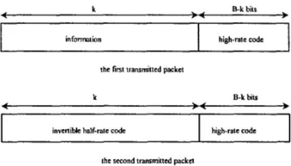
The Hybrid-I1 ARQ scheme using FEC codes, which is devised based on the concept that the parity-check bits for error correction are sent to the receiver only when needed, increases the bandwidth efficiency and reduces the average packet delay [ 3 ] . Two linear codes are used in this scheme; one
is a high-rate (B, B-k) code CO, which is designed for error
detection only, the other is an invertible half-rate (2k, k) code
C,, which is designed for simultaneous error correction and
error detection. The packet formats are depicted in Fig. 1. The operation procedure of the hybrid-I1 ARQ is described as following. At first, the transmitting node sends the packet with the high-rate code. When the packet is received successfully, the receiving node sends an acknowledgement (ACK) back to the transmitting node. Otherwise, the receiving node sends a negative acknowledgement (NAK) back and the transmitting node will transmit the corresponding invertible half-rate code for correction. If the packet is successfully corrected, the receiving node sends an ACK back. On the contrary, the receiving node sends a NAK for the retransmission of the high-rate code packet and drops the former one. If the retransmitted one is correct, an ACK will be sent. Otherwise, it will be corrected by the former corresponding invertible half-rate code. If the packet still can’t be corrected, the packet with the corresponding invertible
invertible half-rate code high-rate code
Fig. 1. The packet formats of hybrid-I1 ARQ.
half-rate code will be dropped and a NAK will be sent for the retransmission of the packet with the corresponding invertible half-rate code. This procedure will be repeated until the packet
received successfully [4].
On the other hand, the n-bit-marked error correction scheme employs the physical layer side information to increase the correctness of every transmitted packet for improving the throughput [SI. In this scheme, the transmitting node doesn’t
have to change the structures of the physical layer and the data
link layer. In the receiving node, a side information generator
is added. The receiver structure with binary phase shift keying
demodulator and the side information generator is shown in
Fig.2. We mark the bit, which is in Conditions I1 and 111.
In this paper, we combine the,n-bit-marked error correction and the hybrid-I1 ARQ scheme. The operation procedure of this combined scheme is very similar to that of the hybrid-I1 ARQ scheme. The only difference is that we use the n-bit-marked error correction scheme to increase the correctness of every hybrid-I1 ARQ packet to improve the
throughput. The operation procedure of
this
combined schemeis described as following. At first, the transmitting node sends the packet with the high-rate code. If the packet is received successfully by employing the n-bit-marked error correction scheme, the receiving node sends an ACK back to the
transmitting node. Otherwise, it sends a NAK back to request
for transmitting the packet with the corresponding invertible
half-rate code.
This
packet is also received by employing then-bit-marked error correction scheme. If it is correct or can be corrected by the n-bit-marked error correction scheme, the receiving node sends an ACK back. If not, it also can be used to correct the information packet. If the packet is successfully corrected by the corresponding invertible half-rate code, the receiving node sends an ACK back. On the contrary, the receiving node sends a NAK for the retransmission of the packet with high-rate code and drops the former one. If the
retransmitted one is correct or can be corrected by the
n-bit-marked error correction scheme, an ACK will be sent.
~~
‘The work IS supported in part by the National Science Council, R.0.C
ride information generator
Fig.2: receiver structure
Otherwise, the former packet with the corresponding invertible half-rate code will be used to correct the packet.. If the packet still can't be corrected, the packet with the corresponding invertible half-rate code will be dropped and a NAK will be sent for the retransmission of the packet with the corresponding invertible half-rate code. This procedure will be repeated until the packet received successfhlly.
11. THE THROUGHPUT ANALYSIS
The throughput of the hybrid-I1 ARQ scheme is effected
by the values of 41 and 42. 41 is the conditional probability
that the packet can be recovged by .the second transmitted packet when the first transmitted packet is detected error. 42 is the conditional probability that the packet can be recovered by the third transmitted packet when the first and second transmitted packets are detected error and can not be recovered by the packet with the invertible half-rate code.
For the combination the hybrid-I1 ARQ and the n-bit-marked
scheme, 41 can be expressed as
(1)
41 = ( P c + P n ) + Pd&l 4 1 - P c
-
P f l ) ,where P, is the probability of the first packet is received
successfully without invoking the correction algorithm. P,, is
the probability that the erroneous packet is successfully
recovered by the n-bit-marked error correction scheme. Pdcl is
the probability that the first and second transmitted packets are erroneous and can't be corrected by the n-bit-marked error correction scheme but can be recovered by invertible high-rate
code. PddCI can be expressed as
where Pdc is the probability that the first and second
transmitted packets are erroneous but can be recovered by
invertible high-rate code. PA is the probability that the first and
second transmitted packets are detected errors, the first transmitted packet can be recovered by the n-bit-marked error correction scheme and the first and second packets can be
recovered by the half-rate code. PAI is the probability that the
first and second transmitted packets are detected error, the second transmitted packet can be recovered by the n-bit-marked error correction scheme and the first and second packets can be recovered by the half-rate code. PB is the probability that the first and second transmitted packets are
detected error, both can be recovered by the n-bit-marked error correction scheme, and the first packet can be recovered by the half-rate code. The probabilities, P A and, Pal are equal. Pddcl
can also be expressed as
(3)
We assume that there are N marked bits in the first transmitted packet and among them h marked bits are in the
first k bits of the packet. Let t be the correction power of the
invertible half-rate code and n is the maximum number of
marked bits of the n-bit-marked error correction scheme. The
probability PA is given by
Pddcl = Pddc - 2PA i-PB
(4)
where
P,
is the BER, B is the number of bit in a packet. P I is the probability that the signal energy of a received bit is largerthan r (the threshold of side information generator). P2 is the
probability that the energy of a received bit is fallen in the (0, r)
region. P3 is the probability that a received bit is fallen in the (0,
-r) region. The detailed derivation of PA is presented in the
Appendix.
where PI<, is the probability that a packet with one to (t-j)
errors in the first k bits can be recovered by the
n-bit-marked error correction scheme and PIU is the probability that a packet with one to t errors in the first k bits can be recovered by the n-bit-marked error correction scheme. Similarly, when the n-bit-marked error correction scheme is
employed, q2 is given by
1-1
C A l ( i ) s , ( t - i)[l - A(0) - s(t - i ) - s2 (i)] ( 8 )
,=O
and
A(i) = C:pe'(l - P.)~-' (9)
where P, is the probability of the first packet is received
successfully without invoking the correction algorithm.
P,
isthe probability that the erroneous packet is successfully
recovered by the n-bit-marked error correction scheme. A(i)
is the event that the first k bits of the thud transmitted packet contain exactly i errors. A I(i) is the event that the first k bits of the third transmitted packet contain exactly i errors and can not be corrected by the n-bit-marked error correction scheme.
S(j) is the event that the first k bits of the third transmitted packet contain one to i errors. S,(i) is the event that the first k
bits of the third transmitted packet contain one to i errors and
can not be corrected by the n-bit-marked error correction scheme. S,(i) is the event that the first k bits of the third transmitted packet contain ( t - j + l ) to k errors and can be corrected by the n-bit-marked error correction scheme.
Denote that
Y
= 41 +42 - q1q2Then the throughput of the combination scheme with receiver buffer of size N has a lower bound as
q 2 6, /(6, + 6, + 6 , N ) (17)
where
The throughput versus
BER
with t= 3, 5 or 10 are plotted inFigs.3-5. In Fig.3, the maximum gain is 0.26. Here the gain is
defined as the difference of the throughput of the hybrid4
A R Q
and that of the combination of the hybrid-I1A R Q
and the n-bit-marked error correction scheme. The maximum gains are0.24 and 0.17 for t=5, n=10 and t=10, n=15 as shown in Figs.4
and 5. It is observed that the proposed scheme can increase the packet throughput significantly at BER around 1.5x10³, where
the throughput of the conventional selective repeat
A R Q
isalmost zero.
Iv.
CONCLUSIONIn this paper, we combine the hybrid-I1
A R Q
and then-bit-marked error correction scheme to improve the throughput performance. We take the advantages of using side information and FEC codes. The numerical results show that this scheme can improve the throughput significantly. The maximum gain of this combination scheme is 0.26 at BER around 1.5~10'. This scheme needs computation power in the
receiver. It is expected that when the cost effective digital
signal processing integrated circuit chip is available, this
scheme can be practical.
0.9 . 0.8 . 0.7 . 0.6 .
g
0.5 .e
0.4 . 0.5 . 0 2 . 0.1 .Fig.3.The throughput of the combination of n-bit-marked
error correction (n= 3, 5 or 10) and hybrid-I1
A R Q
withhybrid4 ARQ (1=5 ) --- ride-information (n=3) aide-information (n=5) 0 8 - - - ride-information ("=lo) - z 0 7 - E 0 6 - I O 4 - 5 3 0 5 - P 0 3 - 0 2 0 1 0
Fig.4.The throughput of the combination of n-bit-marked
error correction (n= 3, 5 or 10) and hybrid41 ARQ with
t=5. The buffer size is 128 and the packet size is 524.
11
- -
___-
.,hybrid-11 ARQ (t=lO )
... ade-mforrnalion [n=V
--- side-information (n-IO)
-:. side-information(n-15)
- . 0.8
Therefore, when h=O, the total probability of PA can be expressed as
PA =
2
k;-'P,H-NkP2 + P3)N - PzN@C:P.'(/ - p ) k - ' ] - ( I - P)E}N = l ,=O
(A.4)
Next, we assume N=l and h=land PA is expressed as
If N=2 and h=l, then PA is given by
If N=3 and h=l, then PA is given by
0.6 - P 9 0 5 - j O 4 . 0 3 - 0.2 . O l - 01 lo" 10" 10.' 10.' 10.' \ 1 +b@kF;B"4k4+412-4'
1 1
-(l-ef (A.7) bit e m r rataFig.5.The throughput of the combination of n-bit-marked
error correction ( ~ 5 , 10 or 15) and hybrid-I1 ARQ with
t=lO. The buffer size is 128 and the packet size is 524.
If N=n and h=17 then can be expressed as
APPENDIX
First, we assume that N=l and h=O. Then PA can be
(A.8) expressed as
(A.1)
If N=2 and h=O, then PA can be expressed as Therefore, when h=l, the total probability of PA can be
expressed as
Then, when h=2, the total probability of PA can be derived as
Therefore, the total probability of PA is given by " "
p* =
c
CCfc;:;p:-Nh=ON=h
REFERENCE
[ 1 ] Andrew S. Tanenbaum, Computer Networks, Prentice
Hall, New Jersey, third edition, 1996.
Shu Lin and Daniel J. costello, Jr., Error Control Coding :
Fundamentals and Applications, Prentice Hall, United States ofAmerica, 1983.
Shu Lin and Philip S. Yu, 'A hybrid ARQ scheme with
parity retransmission for error control of satellite
channels', IEEE Trans. Commun. Vol. Com-30, no.7, pp.
[2]
[3]
1701-1719, July 1982.
[4] Yu-Ming Wang and Shu Lin, 'A modified selective-repeat
type-I1 hybrid ARQ system and its performance analysis',
IEEE Trans. on Comm., Vol. Com-31, No. 5, pp. 593-607,
May 1983.
Jingshown Wu and Cheing-hong Lin, 'Throughput of
ATM Packet over Wireless Rayliegh Channel',
proceedings of IEEE ATM workshop99, Kochi Japan,
May, 1999
John
G.
Proakis, Digital Communication, Prentice Hall,Singapore, third edition, 1995. [5]