MODELING AND TORQUE PULSATION Rl3DUCTION FOR A SWITCHED RELUCTANCE MOTOR DRIVE SYSTEM
**
*
**
Bin-Yen Ma, Tian-Hua Liu, and Wu-Shiung Feng
*
Department of Electrical Engineering National Taiwan Institute of Technology
Taipei, Taiwan 106, R. 0. C. ABSTRACT
This paper presents a new method for analysis and design of a three-phase switched reluctance drive system. First, the mathematical models of a switched reluctance motor under an a-b-c stationary frame and a d-q synchronous frame are proposed. Next, two current cormnand waveform that produce a lower torque pulsation than traditional switched reluctance drives are discussed. Finally, some simulation and experimental results are presented to validate the theoretical analysis. This paper presents a new direction in analysis and control of a switched reluctance motor.
I. INTRODUCTION
Switched reluctance drive technology has undergone significant development over the last two decades. Compared with the induction drive or the permanent magnet synchronous drive, the switched reluctance drive has many advantages, for example, the simple and rugged construction of the motor. It has high efficiency and can endure high temperatures because its rotor has no winding. The switched reluctance drive system, therefore, can be operated efficiently in hostile environments. There have been many studies on the switched reluctance drive. For example, Miller et. a1 developed a drive system for a switched reluctance motor [l]. Lipo. et. al proposed a new salient reluctance motor drive [2]. In addition, M. Ehsani et. al studied sensing rotor position by measuring mutually induced voltages or a frequency modulated converter [3].
However, these papers studied the switched reluctance This research is supported by National Science Council of the Republic of China under grant NSC 85 -2213 -E 4 1 1 -031.
**
Department
of
Electrical Engineering National Taiwan University Taipei, Taiwan 106,R.
0. C.motor by using only the a-b-c stationary frame. In addition, the phase current command of the drive system is a square waveform due to the assuniption that each phase's self-inductance of the motor is a trapezoidal waveform. In the real world, however, the self-inductance is not a trapezoidal waveform because of the nonlinear nature of the switched reluctance motor. Torque pulsation is therefore produced.
In this paper, first the models of a three-phase switched reluctance motor (SRM) under an a-b-c stationary frame and a d-q synchronous frame are presented. The torque equation is derived according to the real self-inductances of the SRM. Next, two improved current command waveforms of the SRM are derived. These current conmands produce lower torque pulsation. Finally, some simulated and experimental results validate the theoretical analysis. This paper proposes a new direction in the study of the SRM.
11, SYSTEM DESCRIPTION AND MODELING A. System Description
The block diagram of
a
switched reluctance drive system is shown in Fig. 1. This system consists offour
major parts:
a
motor,a
current-regulated converter, a controller, and sensors. First, the controller computes the speed error and then executes the control algorithm. Next, the controller determines and outputs the current commands to the current-regulated converter. The current-regulated converter controls the three phase currents to follow the current commands. The sensors consist of the current and position sensors. The whole system consists of a current loop and a speed loop. By suitably adjusting the amplitude and frequency of the currents, a closed-loop system is thus achieved.I Hlcroprocessor System I - f q - fd Hardware
-COS
e,
COS (e,-izo")
COS ( oe+izo0)- - fa-
-
-
sinee sin(Be-12O0) s i n ( ~ ~ + 1 2 0 ' ) fb 0 . 5 0 . 5 0 . 5 I POSltlO" Detectlng circuit EncoderFig. 1 Block diagram of a SRM drive system.
The SRM consists of two parts: stator and rotor. The stator has concentrated windings but the rotor has no winding. Both stator and rotor are salient structures. The air gap, therefore, is not uniform.
B. Stationary frame model
The SRM is a nonlinear system. Generally speaking, the self-inductance of the motor is related to the position of the rotor. We can assume that each phase's self- inductance is not related to its phase current or the other phase's self-inductance because their correlation is very small. The flux linkage of the motor, therefore, can be expressed as
j=a, b, c (1)
where A . is the flux linkage of each (a, b, c) phase, L. is each phase's self-inductance, i. is each phase's current, and Be is the electrical rotating angle. The self-inductance of different phases has the same shape but shifts a 120' electrical phase angle. The dynamic equation of each phase voltage is
X . ( B , i.) = L.(B ) i
J e J J e j
J J
J
v . ( ~ ) = R i.
+
&
xj
(oe,
ij)J
e
S Jwhere v. is the phase voltage, Rs is the phase resistance, and wr is the electrical rotating speed. The torque of the motor is
J
where Nr is the number of rotor teeth, La, Lb, and Lc are the a, b, c phases' self-inductances. The electrical speed of the motor is
(4)
d 1 1 1
x w - - - = - ( T - B
w
--T rN~
J~e
m rN~
1)where Jm is the inertia, Bm is the viscous coefficient, and T1 is the external load.
111. TORQUE PULSATION REDUCTION The major disadvantage of the SRM is that its torque pulsation is larger than other machines. There are many papers which have proposed different methods to reduce the torque pulsation of a SRM. These papers [4]-[5],
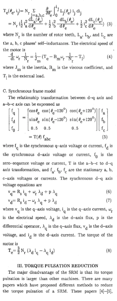
however, have not presented simple and systematic methods to derive the phase current command wavefornls which can reduce torque pulsation. This motivated us to study this subject. Fig. 2 shows the ideal self-inductance waveforms and the ideal current command waveforms of a SRM. Each self-inductance increases/decreases linearly when its related stator and rotor teeth move closer or farther away. The self-inductance is maintained at a constant when its related stator and rotor teeth are aligned. According t o the self-inductance waveforms, we can obtain the ideal phase current commands which
can
produce maximum average torque and minimum torque pulsations. The current command of each phase is a square wave with a 1/3 duty cycle. Each phase's current is
injected into the motor when its related self-inductance is
increased. By summing-up the three-phase torque, we can obtain the smoothing torque. In a real system, the self-inductance, however, is not a trapezoidal waveform. The real self-inductance can be approximately expressed as [3], [4]:
N
Lc( $)'LIS+ LA- LBICOS ( $+120°)
N n=2,3..
+
C L~~ ~ o s [ n ( 8 ~ + 1 2 0 ~ ) ] and'ezN, 'rm (12)
where L is the leakage inductance,
LA,
LB1, LBn are the parameters of the self-inductAnce, and 1 9 ~ ~ is the mechanical shaft angle.1s
Inductances (ideal)
C u r r e n t commands (Ideal)
(b)
Fig. 2 Waveforms
of
theSRM
(a) ideal inductances (b) ideal current commands.The self-inductances are not trapezoidal waveforms. In this paper, some modified current command waveforms, have therefore been derived according to the proposed a-b-c and d - q coordinate mathematical models.
A. METHOD 1
Method 1 is derived from the stationary frame model of the motor. Take the a-phase as an example: the torque produced by the a-phase is
< # < #
$on- e - aoff T a= T e= constant
=O else (13)
The electrical conduction period of the a-phase is 'a cond= 'a off - 'a on
where 'a cond is the electrical conduction period of the a-phase current command, 8, off is the electrical turn-off angle
of
the a-phase current,Ba
on is the electrical turn-on angle of the a-phase current, and q is the phase number of the motor. From equations (3), (9), and (13),we can obtain (15) f l a 'a( 'e)= J0.5Nr(LB1sinBe+ N
c
LBn n sin(n$)) n=2,3.. .The b-phase and c-phase current commands show the same waveforms as the a-phase, however, the b-phase lags/leads the a-phase 120' and the c-phase lags/leads the a-phase 240' when the motor is in clockwise/counter clockwise rotation.
B. Method 2
In method 2, first we select only the fundamental and dc components as the self-inductance. The harmonics of the self-inductance in equations (9)-(11) are neglected because they are very small when compared with the fundamental component [GI. Then, the approximate inductances are
1
a q
ib = T(6) id - i
LA( 6) g LIS+ LA- LBICOS( $-120°) (17)
-
1 1
where
L,,
Lb, L; are approximate values of the self-inductances in the a-b-c stationary frame. The approximate values of the self-inductances in the d-q synchronous frame are:- L i s + L ~ - L ~ i 0 0
- 0 L i s + L ~ + L ~ ~ 0 (19)
- 0 0
Lis-
axis inductances. The L i and L 1 are constant values. If the current commands are sinusoidal waveforms, the
9
mutual inductances have to be considered. Then, the Ld and L '
of
the equation (19) are multiplied by 1.5. The d-q axis currents (id and i ), which are orthogonal,can
be9 Q defined
as
id = iscos6
i = i sin6 q s and i S=I=
where is is the amplitude of the current vector, & is the phase angle of the current vector. The torque can be
derived from equation (8), and it is expressed as
I 1
(24) T e = ~ 3 Nr (L - L ) i i
d q d q
If we choose
6=
45O, then the torque ratio Te/is has a maximum value, and this control is called "maximum torque" control. On the other hand, if we maintain idas a
constant, and only adjust i then the torque is proportional to i This is called "field oriented" control.
4' q'
The phase currents ia, ib, ic can be computed according to the coordinate transformation:
The current command waveforms ia, ib, i, are sinusoidal waveforms in spite of maximum torque or field oriented controls. By suitably adjusting the amplitude, frequency, and phase, the torque can be effectively controlled. The torque pulsation due to the harmonics of the self-inductances is neglected here. The reason is that the harmonics of each phase self-inductance are much smaller when compared with the fundamental sinusoidal component of the self-inductance. If we consider both the average torque and the torque pulsation, then
N
3 3
T = - N e 2 r (2L B1 )i d q i + - N E 2 rn=2,3.., (2nLBn)idniqn (26) where idn and i are the equivalent d-q axis currents with the shaft angle nee. The currents idn and i have the shaft rotating speed noe because they are related to the nth harmonics of the self-inductances.
qn
qn
N.
SIMULATION AND EXPERIMENTAL RESULTSThe implemented system is shown in Fig. 1. The SRM is 3 phase, 8 pole (rotor), 10 HP. The parameters of each phase of the self-inductance are Lls = 7.5mH, LA= SOmH, LB1= 32.5mH, LB2= -4.9mH, LB3= O.G22mH, LB4' 2.2mH, LB5= -1.52mH. The other parameters of the SRM are: R,= 2f2, Jm= 0.0222N-m-sec /rad, and 2
Bm= 0.00028 N-m-sec/rad. A unipolar current regulated converter is designed for the traditional square wave current command and the proposed method 1 current command. Another bipolar current-regulated converter is implemented for the sinusoidal waveforms (method 2). The digital controller is iinplemented by a 32-bit 16.7MHZ Motorola MC68020 moiioboard microprocessor. The controller determines the reference stator currents by looking up tables. The sensors consist of three Hall-effect sensors and
an
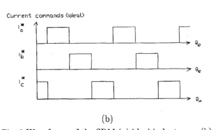
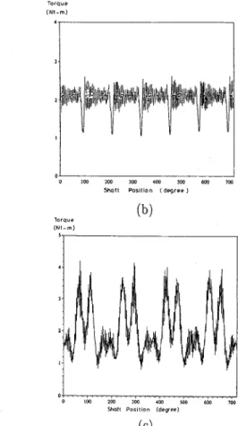
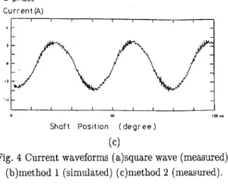
encoder. Some simulated and experimental results are shown here. Fig. 3 shows the simulated torque to rotor shaft position curves (a-phase) for different waveform commands. Method 1 performs better than any other method. Method 2 has the advantage that no phase commutation is required. In the real world, therefore, the torque pulsation due to phase commutation can be eliminated by using method 2. The traditional square wave performs the worst because the self-inductances of the SRM are iiot trapezoidal waveforms. Fig. 4 shows the measured and simulated current waveforms of the stator. The waveforms are measured from the implemented drive system. The a-phase self-inductance of the SRM is shown in Fig. 5 . The inductance is not trapezoidal but close to sinusoidal waveform with harmonics. Fig. 6 shows the torque-current curves of proposed method 2. When kept at the same current amplitude is, the maximum torque control produces larger torque than the field oriented control. However, the speed-loop controller design of maximum torque control is more difficult due to its nonlinear relationship between torque and the q-axis current. Fig. 7 shows the measured speed responsesof
the different current commands.TQiq YP I NI-m) I I 0 ' I 0 IW I W IW I W 5W 6w llyl
Shaft Position [degree)
( N I - m )
'
I
%oft Position ( d e g e e l
(c)
Fig. 3 Steady-state torque of different current coinniaiids (T1=2N.m)(a)square wave (b)method 1 (c)method 2
O - p h a s e Curren f I A l
I
a-phase
C u r r e n t (A)
l"' Shaft Posit ion ( d e g r e e )
(cl
Fig. 4 Current waveforms (a)square wave (measured) (b)method 1 (simulated) (c)rriethod 2 (measured).
L a mH 1501 "1 I I '0 100 200 300 400 500 600 700degree Angle
Fig. 5 The self-inductance of the SRM (the a-phase).
N.,T
... maximum torque cDnlrOl 12
... field odenlcd control
~ t o t o : 5 Current
Fig. 6 Torque-current curves of method 2.
*.d r,m, n 0 in 1.0 -IW sec (b)
Fig. 7 Speed response (a) square wave (b) method 2. V. CONCLUSIONS
In this paper, three different current waveforms for a SRM are studied. These current waveforms perform with different torque characteristics. The theoretical analysis and experimental results are presented. The experimental results show the possibility of using these proposed command waveforms to replace traditional square wave commands. Tliis paper proposes a new direction in the design of a SRM drive system.
REFERENCES
M. R. Harris, J. W. Finch, J. A. Mallick, and T. J. E. Miller, "A review of the integral-horsepower switched reluctance drive," IEEE Trans. Ind. Appl., vol. IA-22, no. 4, pp. 716-721, July/Aug 1986.
L. Xu, T. A. Lipo, and S. C. Rao, "Analysis of a new variable-speed singly reluctance motor utilizing only two transistor switches," IEEE Trans. Ind. Appl., vol. IA-26, no. 2, pp. 229-236, Mar./Apr. 1990.
I. Husain and M. Ehsani, "Rotor position sensing in switched reluctance motor drives by measuring mutually induced voltages," IEEE Trans. Ind. Appl., vol. IA-30, no. 3, pp. 665-672, May/June 1994.
R. S. Wallace, D. G, Taylor, "A balanced commutator for switched reluctance motors to reduce torque ripple," IEEE Trans. Pow. Electron., D.
S.
Reay, M. M. Moud, T. C. Green, and B. W. Williams, "Switched reluctance motor control via fuzzy adaptive systems," IEEE Control Systems, vol. 15, no. 3, pp. 8-15, June 1995.N. Matsui, N.