Energy-Eff icient Flash-Memory Storage Systems
with an Interrupt-Emulation Mechanism*
Chin-Hsien Wu, Tei-Wei Kuo, and Chia-Lin Yang
{d90003, ktw, yangc} Qcsie.ntu.edu.tw
Department of Computer Science and Information Engineering
National Taiwan University Taipei, Taiwan,
106
ABSTRACT
One of the emerging critical issues for Rash-memory storage systems, especially on the implementations of many embed- ded systems, is on its programmed
110
nature for d a t a trans- fers. Programmed-110-based d a t a transfers might not only result in the wasting of valuable CPU cycles of microproces- sors but also unnecessarily consume much more energy from batteries. This paper presents a n interrupt-emulation mech- anism for flash-memory storage systems with a n energy- efficient management strategy. We propose to revise the waiting function in the Memory-Technology-Device (MTD) layer t o relieve the microprocessor from busy waiting and t o reduce the energy consumption of the system. We show t h a t energy consumption could he significantly reduced with good saving on CPU cycles and minor delay on the average response time in the expcriments.Categories and Subject Descriptors
C.3 [ S p e c i a l - P u r p o s e And A p p l i c a t i o n - B a s e d S y s t e m s ] : Real-time and embedded systems; D.4.2 [ O p e r a t i n g Sys- tems]: Secondary storage; B.3.2 [ M e m o r y Structures]: Mass storage
General Terms
Design, Performance, Algorithm
Keywords
Flash Memory, Storage Systems, Embedded Systems, Interrupt- Emulation 110, Energy-Efficient, Programmed 1 1 0
1. INTRODUCTION
Flash memory has been widely adopted in various plat- forms for storage systems. Many of its usages are now well 'Supported in part by a research grant from the National Science Council under Grant NSC 92-2213-E-002.065 and a research grant from the Academia Sinica.
Permission to make digital or hard copies of all or pan of this work far personal or cla~sroom use is granted without fee provided that copies are
not made or distributed for profit or commercial advantage and that copies bear thin notice and the full citation on the first page. To copy otherwise, to republish, to post on scmers or to redistribute to lists, requires prior specific permission and/or a fee.
CODES+ISSS'O4, September 8-10,2004, Stockholm, Sweden. Copyright 2W ACM 1-581 13-937-3/04/0009
...
$5.00.beyond its original designs. Application programs or operat- ing systems on ernbedded systems usually use programmed 110 t o access flash memory. Such a phenomenon might not only result in the wasting of valuable CPU cycles of micro- processors hut also unnecessarily consume much more en- ergy from batteries, especially for embedded systems.
In past few years, many excellent research results have been proposed far the performance enhancement of Rash- memory storage systems, e.g., [l, 5, 6,
8,
9, 101. In particu- lar, Wu, et al. proposed t o adopt SRAM as write buffers and presented several cleaning policies for garbage collection [lo]. Kawaguchi, et al. proposed the cost-benefit policy [5], which uses a value-driven heuristic function as a block-recycling policy. Kim, et al. 161 proposed t o periodically move live d a t a among blocks so t h a t blocks have more even lifetimes. To improve the overall performance, Chang and Kuo [l] pro- posed a n adaptive striping architecture which consists of several independent banks. While energy-efficient designs have become an important issue on embedded systems, re- searchers have started exploiting energy-aware designs of flash-memory storage systems, e.g., [2, 31. In particular, Douglis, et al. [3] provided a series of energy consumption measurement for flash memory under different percentages of capacity utilization.The objective of this research is t o evaluate the feasibility and benefits of energy-efficient flash-memory storage sys- tems with interrupt-emulation. The goal is not only t o re- lieve the microprocessor from wasting valuable CPU cycles because of the programmed-110-based d a t a transfers of flash memory in many existing implementations, but also provide a n energy-efficient strategy. First, we propose an interrupt- emulation mechanism for Rash-memory storage systems, in which the the waiting function in the Memory-Technology- Device (MTD) layer is revised to relieve the microprocessor from busy waiting. Each 110 request of the flash-memory storage system is inserted into a queue for the storage system for scheduling, where a single task dedicated for the storage system is responsible of scheduling and dispatching requests and notifying the completion of each request. Furthermore, a n energy-efficient strategy is presented for multi-hank flash- memory storage systems, especially on when t o switch the power state of each flash-memory bank. We show t h a t en- ergy consumption could be significantly reduced, and much saving on CPU cycles could be achieved. In the experiments, i t was also observed that only minor delay on the average response time of
110
requests in realistic traces.The rest of this paper is organized as follows: Section 2 provides a n overview of flash memory. Section 3 introduces
the interrupt-emulation mechanism. Section 4 provides a n energy-efficient strategy based on the interrupt-emulation mechanism. Section 5 shows experimental results. Section
6
is the conclusion.2. FLASH-MEMORY CHARACTERISTICS
NAND flash memory is popular in the markets and con- sidered for storage systems designs. NAND flash-memory might consist of multiple hanks, and each bank is a flash unit that could operate independently. Each bank is par- titioned into blocks, where each block is of a fixed number of pages. A block is the smallest unit of an erase opera- tion, while read and write operations are handled by pages. T h e typical block size and page size are 16KB and 512B, respectively. Because of the hardware characteristics, data could not he overwritten over pages on updates. Instead, d a t a must be written to some free space. The update strat- egy is called "out-place update". Pages that store the most recent versions are called "live pages", and pages that store old versions are called "dead pages".
Because of the out-place update strategy, a dynamic ad- dress translation mechanism is needed to map a given LBA (logical block address) t o the physical address where the valid data reside. To accomplish this objective, a RAM- resident translation table is adopted. The translation table is indexed by LBA, and each entry of the table contains t h e physical address of the corresponding LBA. Each entry in the table is a triple (bank-num, block.nam, page-num) indexed by LBA, where each triple of an LBA indicates its corresponding hank number bank-num, block number blocknum; and page number p a g e n a m .
After a certain number of page writes, the amount of free space on flash memory would be low. Activities that consist of a series of reads, writes, and erases with the intention t o reclaim free spaces would then start. The activities are called "garbage collection" and considered as overheads in flash-memory management. The objective of garbage col- lection is to recycle dead pages scattered over blocks so that they could become free pages after erasing.
3. AN INTERRUPT-EMULATION MECHA-
NISM FOR FLASH-MEMORY STORAGE
SYSTEMS
3.1 System Architecture
Table 1: NAND-Flash Performance fSamsune K9F6408UOA 8MB NAND flash memory
j
The setuolhusv Dhase of read
I
27/25Phase
I
Interval (ps).,
I IThe setup/busy phase of write
i
The setup/busy phase of erase1
27j350 31/2500
Due t o the hardware characteristics of flash memory, ap- plication programs or operating systems on many embedded systems must use programmed
110 t o access flash memory.
The operation model of NAND flash, in general, consists of two phases: setup and busy phases. For example, the first phase (called "setup" phase) of a write operation is for com- mand setup and data transfer. The command, the address,and the data are written to proper registers of flash mem- ory in order. The second phase (called "busy" phase) is for busy-waiting of the data being flushed into flash memory. The operation of reads is similar t o t h a t of writes, except that the sequence of data transfer and busy-waiting is in- verted. The phases of a n erase is as the same as those of a write, except that no data transfer is needed in the setup phase. Note that writes and erases are time consuming, and most of the time is spent in the busy phase, where busy waiting occurs. The performance of NAND flash memory is summarized in Table 1.
Figure 1: System Architecture
The system architecture of a flash-memory storage system consists of two layers, as shown in Figure 1. They are the Flash Translation Layer (FTL) and the Memory Technologv Device (MTD) layer. The file systems layer is over the flash- memory storage system t o provide a logical file interface for applications. FTL provides block-device emulation for transparent access from file systems without any modifica- tions t o existing file-system implementations [12]. Garbage collection, and address translation are handled in FTL. The MTD layer provides handling routines for read, write and erase operations, between devices (e.g., flash memory) and an upper layer (e.g., FTL) [ll].
In this paper, we propose t o provide an 1/0 request model for interrupt emulation (Please see Section 3.2.1) and t o re- vise the waiting function in the MTD layer to relieve the microprocessor from busy waiting (Please see Section 3.2.2). In the
MTD
layer, we will present a n energy-efficient strat- egy for multi-bank flash memory (Please see Section 4) , es- pecially on when to switch the power state of each flash- memory bank.3.2 System Design
3.2.1 An
U0
Request Model for an Interrupt-Emulation
Mechanism
An
110
request could be modelled by a tuple ( P I D , topi,. . .
,
op,}), where P I D denotes the ID of the process that issues the operations in the ordered list { o p ~ ,.
. .,
op,}. Each el- ement in the ordered list lop,,. . .
,
opn} t h a t represents an operation over the flash-memory storage system, such as a read, a write, and an erase, must he executed according to its index order in the list. For example, an operation op, could be ( R E A D , (bank,, block,, p a g e , ) , read-data), ( W R I T E , (bank,, block,, pagei), write-data), or ( E R A S E ,S C H E D UL lN G:
DISPATCHING
Schedule 110 requests of the U0 queue aceording to some criteria for each U0 q u e s t R in the U 0 queue do
for each operation op in R do
Executeop //&tup Phare
ifvpisawtileoranerascthan end if
The MTD dispatcher invokes a waiting function IISusy Pharr
end for
I* NOTIFYING V
The MTE dispatcher rc~umcs the corresponding VO-questing pmess of R
end for
F i g u r e 2: The MTD d i s p a t c h e r
(bank,, block;)), where bank;, blocki, and page, represent the bank number, the block number, and the page number of the corresponding operation, respectively. When a prw cess invokes a n
110
system call, such as fwrite() or fread(), the file system might issue one or more requests t o FTL t o access data in the flash memory. FTL would then issue one or more110
requests t o the MTD layer.An
110
queue is provided in the MTD layer for inter- rupt emulation and energy-efficient design (Please see Sec- tion 4). Each110
request received by the MTD layer is inserted into the 110 queue and wait for the dispatching t o the flash memory. 110-requesting processes would suspend themselves when their110
requests are inserted into the 1 1 0 queue. A system task, referred to as the M T D dispatcher, dispatches the first110
request in the queue, and would invoke a waiting function to enter the busy phase if the o p eration of the110
request is a write or an erase (Please see Section 3.2.2). When a n I f 0 request completes, the MTD dispatcher would resume the corresponding process. The work of the MTD dispatcher is summarized in Figure 2.3.2.2
The Design of the Waiting Function
In*oklhirnunghllxuan,ti"8f"~tim
f
,wok U x r u u n l f u n d r n ScwpPhlx B m y k/c
Sclvpphav Busyphav Emsmg o f a blmk- F i g u r e 3: TWO phases of a f l a s h - m e m o r y o p e r a t i o nA
waiting function is supposed t obe
invoked in the busy phase of a write or a n erase, as shown in Figure 3. In the current MTD layer implementation, the waiting function isinvoked t o yield the
CPU
to other processes because the busy phase of a write or an erase is time-consuming, as shown in Function 1 in Figure 4. The invocation of yield() would virtually move the 110-requesting process (in fact, it is the operating system running on behalf of the process) t o the ready queue. If the 110-requesting process that in- vokes yield() has the highest priority among ready processes in the ready queue of the operating system, then the110-
requesting process would be dispatched such that it invokes yield() again, and the procedure repeats for the "timeout" period of time. Because the I/O-requesting process tends t o be the highest priority process, such a behavior could be
considered as a variation of programmed
110.
I t might not only result in the wasting of valuableCPU
cycles but also unnecessarily consume much more energy from batteries, es- pecially for embedded systems. Note that no invocation of the waiting function is done for reads because their busy phase is short.Function 1 T h e original waiting function
Input 2." operation o p : a write o r a" erase i f o p is 1 write ,hen
timeout = the time o f the busy p h a s e for the writing o f n page
timeoul= the lime o f the busy phase for the errsing o f r block else if o p is an erase then
end if
while timeout is valid do if op finishes then else end if end while if o p fails then end i f return
yield0 ( the flash memory is busy in the busy phase )
verify the status o f the operation o p
Function 2 T h e proposed waiting function
Input a" operation op : a write or a" erase if u p is 61 write then
else if op i s an erase then
timeout = the time o f the bury p h n i e for the writing of r page limeout = the time o f t h e busy p h a s e for the erasing of a block
-"A I,
..
rleep(timeouf) ( the flash memory is busy in the busy phase ) if op finisher then
rerum
end if
i f o p fails then
m n if
verify the s t a t u i of the operation op
F i g u r e 4 W a i t i n g F u n c t i o n
Different from the traditional implementations of the MTD layer, we propose t o invoke sleep() in the waiting function to relieve the
CPU
from busy waiting as a part of the proposed interrupt-emulation mechanism. As shown in Function 2 in Figure 4, the busy-waiting whilcloop is replaced with a n in- vocation of sleep(). Such an invocation would put the MTD dispatcher into sleep until the expiration of the "timeout" period, and the MTD dispatcher (also referred t o as the cor- responding 110-requesting process) is moved to the waiting queue of the operating system. When the timeout event oc- curs, the MTD dispatcher is awaken. When all operations in a n110
request complete, the MTD dispatcher resumes t h e corresponding 110-requesting process.Important technical questions for the proposed approach are on the predictability of the timeout period in the wait-
i n g function, the impacts o n the sustern performance, and
the potential overheads. We must point out that the access time of flash memory has a very small variance over widely different workloads. The average time of the busy phase for the writing of a page (512B) was 350 f i s , and t h a t of the erasing of a block (16KB) was 2500 p s. The variance of the access time was roughly between 10 p s and 30 fis. There- fore, the access time of flash memory is highly predictable. In the experiments, we shall provide measured results for t h e system performance under different timeout periods so t h a t users could make the best decision for their selection. T h e impacts on the performance of the flash-memory stor- age system due t o the interrupt-emulation mechanism would
be dominated by that of the invocation of sleep() by the MTD dispatcher and the time t o suspensian/resume
110-
requesting processes (and the MTD dispatcher). We could show in the experiments that the overheads are negligible.4.
THE ENERGY-EFFICIENT STRATEGY
4.1 Overview
In a multi-bank flash system, each bank can switch t o different power states independently. We assume a simple power management policy that switches a hank t o a low power state ( L P S ) once it is idle and a high power state
( H P S ) to service a request, where state switching incurs
both the performance and energy overheads. Consider a 4- bank flash system with 4 requests in the 110 queue, as shown in Figure 5. It requires 14 power state switchings, as shown in Figure 5.(a). However, it requires only 6 state switch- ings,
as
shown in Figure 5.(b). Based on the observation, a scheduling strategy is needed t o minimize the number of state switchings t o achieve energy saving.L P S i 3 . 4 L P s : 1 4
LPS: L A LPS: i.2
HPS: 1.4 HPS: 3 4
<a, For 110 REqueSls Wilh0"I <b, For 1 1 0 Rcquesls With
Ssheduling Scheduling
F i g u r e 5 : Reordering of Requests
DEFINITION 1. The Schedulzng Problem of I / O Requests:
Given a collection T of 110 requests, and a cost vector
C(r,,r,) for any r, and r, E T , the scheduling problem of 110 requests is t o find a n execution order of T such that the total cost is minimum.
C(r,, 7,) represents the number of power state switchings
required, i.e., C(r,, 7,) = IBank,I
+
IBank,I - 2 t (IBank,n
could be found in an off-line fashion. We referred interesting readers t o 1131 for optimal solution using Branch and Bound. For'the Lesi of this section, we shallfirst address the de- pendency issues of requests t o ensure the correctness of a program execution. We will then present two scheduling heuristics for request scheduling (instead of those based on a pre-determined preferred order). Their performance eval- uation will be included in Section 5.2.
_ .
B i n k j l ) ; where Ba& and Bank, denote two sets'of banks t h a t r, and r, access, respectively.
T h e complexity in solving the scheduling problem of
110
requests depends on the number of combinations of banks, instead of the number of requests in general. Since the number of hanks in many current implementations is very limited, we can either find out the best ordering of bank combinations or run approximation algorithms in the min- imization of state switchings. For example, when there are 4 banks in a system, there are15
bank combinations: { ( 1 ) , ( 2 ) , ( 3 ) , ( 4 ) , ( 1 , 2 ) , (L3L (1,4),(2,3),(2,4),(3,4), ( 1 , 2 , 3 ) , ( 1 , 3 , 4 ) , (2 , 3 , 4 ) , (1,2,3,4)}. We first come out a preferred order of requests in the 15 bank combinations. When re- quest scheduling is needed, we always schedule requests in t h e same bank combination together and schedule requests in bank combinations according to a pre-determined pre- ferred bank-combination order. Note t h a t a preferred order~
4.2
Scheduling Issues on Dependency
Relations
There are three types of operations over t h e flash memory: read, write and erase. At the MTD layer, each operation in a request is associated with a physical block address (PBA). There could he access conflicts among operations on their physical block addresses. We say that two requests R, and
R, conflict with each other if R, and RI satisfy any of the following conditions:
1. There exist one operation in R; and one in R; such t h a t the two operations have the same PBA, and one of them is a write operation (or both are write opera- tions).
2. There exist one operation in R, and one in R, such t h a t one of the two operations is an erase operation, and the other is a read or write operation with a
PBA
inside the block to be erased by the erase operation. For any two conflicting requests, their order is, in fact, not changeable; otherwise, the contents of t h e Rash memory could be different after the reordering of
110
requests or wrong situations could happen. As a result,110
requests in the110
queue are partitioned into two sets: requests with conflicting operations and requests without any conflicting operations. The MTD dispatcher services all requests with conflicting operations first and services all requests without any conflicting operations in a n order determined by the following scheduling algorithms.4.3 Approximation Algorithms
The purpose of this section is t o present two algorithms for the scheduling of non-conflicting requests: A TSPP-based algorithm with an approximation bound and a greedy alg- rithm. T h e performance evaluation of the algorithms will be reported in Section 5.2. Before the presentation of the TSPP-based scheduling algorithm, we shall first prove the triangle inequality property for the cost vector:
LEMMA 1. C ( r 2 , r j ) satisfies triangle inequality i f all I/O
requests are non-conflicting requests. That is, C(ri,r3)
+
C ( r j , r k )
2 C(r;,rk)
for any r;, r j , and r k E a collection ofnon-conflicting requests T .
2r(IBankinBankjl))+(IBanlejI+/BankkI
- 2 * ( I B a n k , nB a n k s ) I ) - (IBankil+lBankbI-2+(IBankinBankbI))=2*lBanle,I-
2*(IBankinBankjI+IBanlc3nBankr,l)+
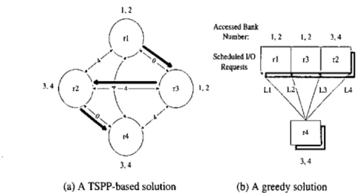
2*IBank,nBankr,l>O.As a result, C ( r ; , r J ) satisfies triangle inequality. 0 We could apply a TSPP-based approximation algorithm on the scheduling of non-conflicting requests because the cost vector satisfies triangle inequality (Please see t o Lemma 1). T S P P is defined as follows [4]: Given a complete graph with vertex V , and a nonnegative edge cost vector for any edges, the travelling salesman path problem is to find a Hamiltonian path with the minimum cost. Figure 6.(a) shows a TSPP-based solution for the example shown in Fig- ure 5. Each request in the scheduling problem is a node in the T S P P instance. The number marked on the edge of
(r,, r,) corresponds to C(ri, rI). We adopt the well-known 2-approximation algorithm' in [7] because of its simplicity 'The 2-approximation algorithm mainly consists of the min- imum spanning tree algorithm and the Eulerian tour.
. z
Applications
1.4
3 , 4
(a) A TSPP-based solution (b) A greedy solution
F i g u r e 6 : S o l u t i o n s based on a TSPP-based a p p r o a c h and a greedy a p p r o a c h
Web Applications, E-mail Clients, MP3 player, and Virtual Memory in implementation. Note t h a t when a new non-conflicting
110
request arrives for scheduling, all scheduled110
re- quests must be rescheduled with the new110
request by the TSPP-based approximation algorithm. The complex- ity of each rescheduling isO(lVl')
for the 2-approximation algorithm.Request scheduling could also be done by a simple and ef- ficient heuristics, referred to
as
the greedy algorithm for the rest of this paper: LetS
be a schedule of all non-conflicting pending 110 requests. When a new request arrives, the greedy algorithm simply scans over the schedule from the front to the end t o find the best place to insert the new request in. The selection is based on the minimization of the final cost. For example, let r4 be a new request, and there are four potential locations ( L l , L2, L3, or L4) for in- sertion, as shown in Figure 6.(b). According to the greedy algorithm, L3 and L4 would be better than L1 and L2 be- cause of less cost. The time complexity of each rescheduling is O(jV1).Total Data Written Total 110 Requests Read
J
Write Ratio Mean ReadIWrite Size5. PERFORMANCE EVALUATION
122 MB 33,000 44%/ 56%
31.3/
16 Pages Activities DurationI
2 Hours -A
series of experiments was conducted on a n Ah4D-Duron (750Mhz) machine running RedHat 7.3 with the proposed MTD layer. The performance evaluation was done over a Cbank NAND type flash system. The size of each bank was 25MB, and the page size was 5 1 2 8 . The characteristics of the traces are summarized in Table 2. Note that the page allocation policy was based on t h e striping architecture [l].The evaluation of the proposed energy-efficient interrupt- emulation mechanism was done in two parts. First, we demonstrated the capability of the interrupt-emulation mech- anism in Section 5.1. We then showed the advantages of the proposed method in energy-efficiency considerations.
5.1
Performance of the Interrupt-Emulation
Mechanism
T a b l e 3: The O v e r h e a d s of the Interrupt-Emulation M e c h a n i s m
I
Ave. ( p s )I
Deviation (ps)Overheads of the
I
20I
10invocation of sleep()
Overheads of the suspension
1
30I
10 and resumption timeOverheads of
I
50I
20each 110 request
The overheads for the supporting of the interrupt-emulation mechanism mainly came from the invocation of sleep() by t h e MTD dispatcher and the time to suspendlresume
110-
requesting processes and the MTD dispatcher. We measured these overheads in the kernel mode for more precise results. T h e results art? summarized in Table 3. We can see that t h e total overheads for each110
request is about 50 p s on average, and the deviation for each 110 request is about 20ps. Compared with the average service time, 2 m s and 6 rns for readslwrites, the performance overheads (that is about 50 ps on average) from the interrupt-emulation mechanism was reasonable.
(C)TOld C0mpimtiO"hC of4hvUPnait? h e n e i when SW=scO and SLLIYO
(d) To3Cornpu~isonTimcafl law rho ti^ h a e s r r r h m S W ; M a a n d S ~
Figure
7:
E x p e r i m e n t a lResults
of theInterrupt-
E m u l a t i o n Mechanism. (SW a n d
S E
denote the t i m e o u t period of the busy phase for w r i t e and erase o p e r a t i o n s , r e s p e c t i v e l y )We measured the accumulated sleep time for 3 different timeout periods, as shown in Figure 7.(a). We can see t h a t longer timeout periods resulted in longer sleep time as ex- pected. During the sleep period of t h e h4TD dispatcher, the microprocessor could be used by other processes thereby in- creasing the system throughput. To quantify this effect, we executed four additional CPU-bound processes with lower priorities than t h e M T D dispatcher. T h e period and compu- tation time of the four CPU-bound processes was described in Table 4. We measured the CPU time spent on these four
processes with and without the interrupt-emulation mech- anism. T h e results are shown in Figure7.(b), (c) and (d). We can see that, with the support of interrupt emulation, these 4 processes obtained far more CPU cycles, compared to those under the original flash driver implementations, and a longer timeout period resulted in a larger discrepancy as expected. Note that process1 obtained more CPU cycles than the other 3 processes did because it had the shortest period.
T a b l e 4: C P U - b o u n d processes
Period (us)
I
300I
3701
710I
780 ComputationI
30I
30I
40I
40I
Process1I
Process21
Process3I
Process41
Time ( p s )I
I
I
I
5.2
Effectiveness
of
the Energy-Efficient
Strategy
I
Number of State Switchings among Power
States
F i g u r e 8: E x p e r i m e n t a l Results of the Energy- Efficient Strategy
The proposed TSPP-based and the greedy algorithms were evaluated for energy efficiency considerations. One impor- tant parameter that affected the effectiveness of the energy efficient strategy was the number of pending requests in the 110 queue when scheduling was performed. We measured the number of state switchings by varying the number of pending 110 requests. The experimental results were shown in Figure 8. We could see that the number of state switch- ings was reduced significantly, compared t o that without request scheduling. As we increased the number of pending 110 requests, better improvement was observed for both of the proposed algorithms. Note that the number of pend- ing 110 requests wa5 mainly determined by the workload in a real system and the timeout period of the MTD dis- patcher. When the number of pending requests was large, the greedy algorithm outperformed the TSPP-based alg* rithm although the TSPP-based algorithm could provide an approximation bound to the optimal solution.
6.
CONCLUSION
The paper proposes an energy-efficient flash-memory stor- age systems with intcrrupt-emulation mechanism to relieve the microprocessor from the wasting of valuable CPU cy- cles in many existing embedded systems implementations. We propose to revise the waiting function in the Memory- Technology-Device layer to avoid busy waiting. An
110
queue and a request-dispatching task are proposed to sched- ule
110
requests and t o notify the completion of each re- quest. An energy-efficient strategy is presented for multi- bank flash-memory storage systems, especially on when t o switch the power state of each flash-memory bank. The strategy is t o minimize the energy consumption of flash memory without resulting in performance degradation. Is- sues on the execution orders of read, write, and erase oper- ations over Rash memory are also explored. We show that energy consumption could he significantly reduced with mi- nor delay on the average response time of110
requests in realistic traces, and much saving on CPU cycles could he achieved.For future research, we should further explore the char- acteristics of flash memory. especially when application se- mantics is considered. With joint considerations of applica- tion designs and flash-memory characteristics, much perfor- mance improvement could be reached with even less system overheads and cost.
7.
REFERENCES
(I] L. P. Chang and T. W. Kuo, "An Adaptive Stripping Architecture for Flash Memory Storage Systems of Embedded Systems," IEEE Einhth Real-Time and Embedded '&chnol&y and Applications Symposium (RTAS), San Josel USA, Sept 2002.
Dynamic-Voltage-Adjustment Mechanism in Reducing the Power Consumption of Flash Memory for Portable Devices," IEEE Conference on Consumer Electronic (ICCE 2001), LA. USA, June 2001.
[3] F. Doughs, R. Caceres, F. Kaashoek, K. Li, B. Marsh, and J.A. Tauber, "Storage Alternatives for Mobile Computers," Proceedings of the USENIX Operating System Design and Implementation, 1994.
intractability", 1979.
Flash-Memory Based File System," USENIX Technical Conference on Unix and Advanced Computing Systems, 1995
.
Management for Flash Storage System," Twenty-Third Annual International Computer Software and Applications Conference October 25 - 26, 1999 Phoenix, Arizona. [7] Vijay V. Vazirani, "Approximation Algorithm," Springer
publisher, 2001.
[a] C. H.
Wu, L. P. Chang, and T. W. Kuo, "An Efficient B-Tree Layer for Flash-Memory Storage Systems," The 9th International Conference on Red-Time and Embedded Computing Systems and Applications (RTCSA 2003). (91 C. H. Wu, L. P. Chang, and T. W. Kuo, "An EfficientR-Tree Implementation over Flash-Memory Storage Systems," The 11th International Symposium on Advances
in Geographic Information Systems (ACM-GIS 2003).
[lo] M.
Wu, and W. Zwaenepoel, "eNVy: A Non-Volatile, MainMemory Storage System," Proceedings of the Gth International Conference on Architectural Support for Programming Languages and Operating Systems (ASPLOS 1994), 1994.
[2] L. P. Chang and T. W. Kuo; "A
[4] M . R. Garey, and D. S . Johnson, "Computers and
[5] A . Kawaguchi, S. Nishiokz, and H. Motoda, "A
[GI H. J. Kim and S . G. Lee, "A New Flash Memory
(111 http://www.linux-mtd.infradead.org/
1121 Intel Corporation, "Understanding the Flash Translation 1131 Theo C. Ruys, "Optimal Scheduling using Branch and
Layer(FTL) Specification''
Bound with SPIN 4.0," Supported by Project AMETIST, Department of Computer Science