permanent magnets, iron cores, and coils, which are all magnetic circuit components. When coils are powered, induced magnetic field generates N and S poles around iron cores. Thus, unlike voice coil motors (VCMs) that employ the Lorentz force, the motion of the moving part in this study is arisen from a property-same poles repel each other while opposite poles attract each other. When compared to conventional VCM actuators in simulation results, the proposed LEA generates larger force, whereas using smaller current.
Index Terms—Auto-focusing, linear electromagnetic actuator, magnetic circuit analysis.
I. INTRODUCTION
L
INEAR electromagnetic actuators (LEAs) commonly ap-pear in phone cameras and digital cameras that are re-quired to be light and thin for portable usage. For auto-focusing (AF), an LEA has to move a lens inside a compact space. The low-current requirement of LEA is essential to conserve bat-tery sources in mobile phones. Thus, a compact LEA for AF has to meet demands for reducing both dimension and power con-sumption. Various AF actuators for phone cameras have been considered by many researches [1]–[3]. In general, there are two types of AF actuators that are used in phone cameras. One is lens-motion AF actuating mechanisms, which may be real-ized by using stepping motors, voice coil motors (VCMs), or piezoelectric transducers. The stepper motors are easy to con-trol and do not need holding power after lens movement is com-pleted. However, the mechanical structure is complex and their volume is relatively large. Using the piezoelectric materials as actuators does not need gears and the power consumption is low, but they are sensitive to temperature and control laws are complex. The VCM has features of small volume, low cost, and easy implementation. Nevertheless, springs are usually used for open-loop positioning control. Thus, holding power is in-evitable. The other type of AF actuators is the lens-modifica-tion AF mechanism, which uses liquid lens and solid-state op-toelectronic devices [4]–[6]. Lens shapes and resulting changes of liquid refractive index are crucial to implementing AF of this type. As a consequence, this type has high technical threshold, high cost, and stringent demand on packaging. The design in this paper belongs to the first type; i.e., lens-motion AF actu-ating mechanisms.The motive of the present novel LEA is to minimize the power consumption and the size, and enhancing magnetic
Manuscript received January 26, 2011; revised April 01, 2011, June 01, 2011, June 13, 2011; accepted June 15, 2011. Date of publication June 23, 2011; date of current version November 23, 2011. Corresponding author: T. S. Liu (e-mail: tsliu@mail.nctu.edu.tw).
Color versions of one or more of the figures in this paper are available online at http://ieeexplore.ieee.org.
Digital Object Identifier 10.1109/TMAG.2011.2160273
flux density. The motion of the moving part is arisen from a magnetic field property—same poles repel each other while opposite poles attract each other, which is constantly applied to rotary motors. Moreover, instead of using spring force in conventional VCMs, the lens motion is subject to closed-loop control. Thus, the holding power is lowered.
Krebs et al. [7] presented an electromagnetic actuator that involves linear or rotary movement. The device consists of permanent magnets, an iron teethed armature, and concentrated coils. Chung et al. [8] presented a doubly salient permanent magnet linear synchronous machine. The proposed structure consists of consequent polar stator to reduce permanent magnet material and modular mover structure to reduce force ripples. Jin et al. [9] presented a topology for a permanent magnet flux- switching linear machine. A prototype machine has been built to validate the theoretical analysis, and measured results agree well with those calculated by the finite element method (FEM). Chen et al. [10] presented models in finite element analysis and design of linear permanent-magnet motors with surface-mounted or interior-buried permanent magnets (PMs). Computer simulation results show that characteristics and dimensions of PMs, shapes, and armature dimensions, and all exciting currents have significant effects on motor performance. Wang et al. [11] presented analytical and measurement tech-niques for quantifying iron loss in short-stroke, single-phase, tubular permanent-magnet machine which is developed for direct-drive linear compressors in refrigeration applications. Slocum et al. [12] presented a linear motion axis, in which the attractive force from the linear motor is used to preload a car-riage supported by rigidly attached porous carbon air bearings.
II. COMPARISON OFPROPOSEDLEAANDCONVENTIONAL
VCM ACTUATOR
Fig. 1 shows the structure of a conventional VCM actuator for AF operation in phone cameras. In general, a VCM actuator consists of two parts: a fixed part includes two PMs, a yoke, and a base; additionally, a moving part consists of a lens module, a lens holder, and a coil. Both fixed and moving parts of the VCM actuator are connected by two spring plates (one upper and one lower), which provide restoring forces to balance the 0018-9464/$26.00 © 2011 IEEE
Fig. 1. Structure of conventional VCM actuator [2].
Lorentz force applied to the moving part when current passes through coils. During AF actuation, the Lorentz force is larger than the sum of the moving part weight and the restoring spring force. Moreover, the spring resistance is in direct proportion to the vertical displacement of the moving part [2]. As a result, such VCM actuators typically have dimensions in the order of
10 mm 10 mm 4.6 mm [13].
Unlike previous research on VCM focusing actuators, a novel LEA for AF of phone cameras is presented in this study as de-picted in Fig. 2(a). The proposed LEA structure can be divided into two parts: a moving part and a fixed part. The moving part shown in Fig. 2(b) comprises a lens module (the diameter of lens size is 6 mm), a lens-holder, and four small PMs. The fixed part shown in Fig. 2(c) comprises a Hall-effect sensor, a printed circuit board (PCB), four coils, two iron cores, and two vertical guide rods attached to a fixed base. As depicted in Fig. 3, when coils are powered, induced magnetic field generates N and S poles around iron cores. Due to the repulsion forces between the same poles and the attraction forces between opposite poles, the permanent magnets N pole on the left-hand side in dotted lines region of Fig. 3 is pushed away from the iron core, while the magnet S pole is drawn toward the right iron core. Accordingly, the moving part goes up. In a similar manner, reversing the cur-rent direction in the coil will make the moving part go down. The motion of the moving part is arisen from a magnetic field prop-erty—same poles repel each other while opposite poles attract each other. The magnitude of magnetic field is detected by a Hall-effect sensor and is converted into an output voltage signal of equivalent intensity. Comparing two actuators presented in Figs. 1 and 2, it can be noted that the proposed actuator does not contain springs that are usually used in conventional VCM actuators. As a result, the device size is reduced.
III. ELECTROMAGNETICFIELDANALYSIS
By Fleming’s left hand rule, the actuation force in the LEA is proportional to the magnetic flux of PM, coil current, and the turn number of the coil. The direction of motive force is perpendicular to directions of both magnetic field and current. In order to obtain the motive force of the LEA, the magnetic flux density of PMs and electromagnets have to be calculated. We carried out electromagnetic simulation using the ANSOFT Maxwell software to calculate the magnetic flux density dis-tribution, as this is shown in Fig. 4. A Maxwell 3D (three-di-mensional) finite-element model is used in simulation. It is seen
Fig. 2. (a) Structure of the propose LEA; (b) moving part of LEA; (c) fixed part of LEA.
Fig. 3. Actuation principle of the proposed LEA. The present pole distribution causes the moving part to move up. However, reversing the current direction in the coil will cause the moving part to go down.
that the magnetic flux distribution has bilateral symmetry due to the same magnitude of currents among four coils, symmetry of component geometry, and spatial arrangement.
Fig. 4. Magnetic flux density distribution in LEA has bilateral symmetry. Two long arc components correspond to two iron cores in Fig. 2.
To calculate magnetic flux, electromagnetic principles [14] are employed:
(1) (2) where denotes the flux density, and is the magnetic field intensity and is the total current density. The flux density can be expressed in terms of magnetic vector potential ; i.e.,
(3) Since PM and ferromagnetic materials are used in the present actuator, there exist the following relationships in magnetic fields:
(4) (5) where denotes the magnetic permeability, is the air per-meability, is the magnetization vector within the PM, and is the PM residual flux density. The magnetic flux propa-gates in the region of air gaps between the moving and fixed parts is written as
(6) where denotes an unit surface and is a vector perpendicular to the surface. The scalar product of the magnetic flux density vector and vector yields
(7) Total flux passing through the iron core cross section with thick-ness is written as
(8) Based on Faraday’s law of induction, the induced voltage in the four coils is
(9)
where is the number of turns in the coil. Finally, (1)–(4) give the actuator force expressed by
(10) where V is the coil volume. The above formulation will be used for theoretical calculation depicted in Fig. 8.
IV. ELECTROMAGNETIC STRUCTUREDESIGN ANDSIMULATIONRESULTS
Having established a basic design structure for LEA, as de-picted in Fig. 2, design parameters i.e., dimensions the of PMs, iron cores, coils, etc., were varied to determine the best design by using FEM.
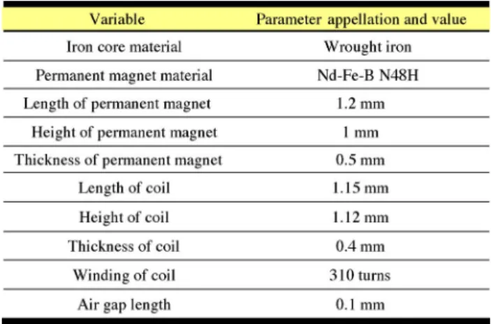
The size of mobile phone cameras dealt with in this study is prescribed as 8.5 mm long, 8.5 mm wide, and 5 mm thick. The lens diameter is 6 mm for the use of eight million pixel cameras. To save energy, the current can not be larger than 80 mA. The above constitutes our design criteria and is prescribed based on specifications of the present market. Table I shows major parameters of the proposed LEA. Based on both camera size and lens diameter, dimensions of permanent magnets, air gap, and coils are determined, as depicted in Table I, where the size of every coil is designed as 1.15 mm long, 1.12 mm wide, and 0.4 mm thick, based on both camera size and lens diameter. However, the coils require further detailed consider-ation. The minimum coil diameter is 0.02 mm. Accordingly, (outside diameter 1.12 mm—inner diameter 0.5 mm)/
mm, which represents coil space in either side. Since wire
diameter mm mm mm turns,
which represents turns per layer coil. Further, coil thickness 0.4
mm/wire diameter layers. Finally.
turns.
Fig. 5 illustrates the upward displacement of permanent mag-nets in the moving part. The LEA displacement is produced by the interaction between PMs and iron cores. Fig. 6 shows the magnetic flux distribution in LEA. The present novel design will produce large with low-current requirement, because its closed magnetic circuit yields little magnetic flux leakage. Fig. 7(a) and (b) shows calculated distributions of magnetic flux
Fig. 5. Displacement of four permanent magnets (green) in proposed LEA.
Fig. 6. Distribution of magnetic flux in LEA magnetic circuit.
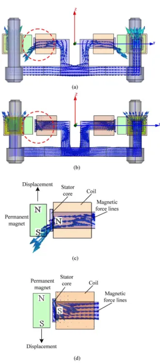
induced within LEA under opposite-direction currents in coils. When the coil is powered, a magnetic field is generated around the iron core. Due to the repulsion forces between the same poles and the attraction forces between opposite poles, the permanent magnets N pole on the left-hand side in Fig. 7(c) is pushed away from the iron core on the right-hand side, while the permanent magnet S pole is drawn toward the right iron core. This results in the upward motion of the permanent magnet as shown in Fig. 7(c). Conversely, when the coil current direction is reversed, the permanent magnet goes downward as shown in Fig. 7(d). In summary, acting on the movable part of the LEA is aligned in the vertical direction and creates the linear motion of the lens module.
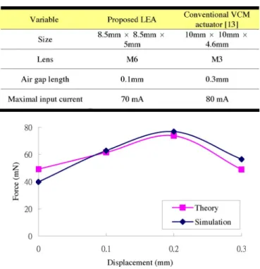
Table II compares the principal characteristics between the proposed LEA and a conventional VCM [13]. As shown in Table II, the proposed LEA size is considerably smaller than conventional VCM actuators. According to electromagnetic principles illustrated in Section III, the current is prescribed as 70 mA. Thus, the current density is calculated as 70 mA/0.345 mm mA/mm . In theoretical solution, this study uses (4) to calculate the magnetic flux density at four points between 0 mm and 0.3 mm. Substituting current densities and into (10) yields the LEA force . Both theoretical and simulation results are depicted in Fig. 8, which shows actuator force varying with the moving part displacement from 0
Fig. 7. (a) and (b) Calculated distributions of magnetic flux under opposite-direction currents in coils. (c) Magnified view of red dashed line region in Fig. 7(a). (d) Magnified view of red dashed line region in Fig. 7(b).
to 0.3 mm. When the moving part moves up 0.2 mm, opposite poles of the moving and fixed parts are nearest to each other.
Thus, the maximum occurs at 0.2 mm displacement.
Fig. 8 also compares theoretical and simulation results con-cerning varying with displacement. Both results are close to each other. Moreover, the maximum can provide 76.8 mN according to FEM. Compared with the conventional VCM actuator, the proposed LEA has a smaller physical size, larger due to smaller current of 70 mA acting on the larger lens of 6 mm, less magnetic flux leakage, and smaller input current
Fig. 8. Comparison of theoretical and simulation results of actuator force
F .
of 70 mA at 3.3 V voltage. As a consequence, the proposed LEA outperforms the conventional VCM.
V. CONCLUSION
This study has presented a novel compact linear electromag-netic actuator (LEA) for AF of phone cameras. The proposed LEA can be applied to phone cameras having over eight megapixels with a diameter 6 mm of lens size. When com-pared to conventional VCM actuators in simulation results, the proposed LEA has smaller physical size, larger , less mag-netic flux leakage, and above all, smaller current. As a result,
[1] M. J. Chung and S. Y. Son, “Development of compact auto focus actu-ator for camera phone by applying new electromagnetic configuration,” J. Mech. Sci. Technol. (KSME Int. J.), vol. 20, pp. 2087–2093, 2006. [2] C. S. Liu, P. D. Lin, P.-H. Lin, S. S. Ke, Y. H. Chang, and J.-B.
Horng, “Design and characterization of miniature auto-focusing voice coil motor actuator for cell phone camera applications,” IEEE Trans. Magn., vol. 45, no. 1, pp. 155–159, Jan. 2009.
[3] H. P. Ko, H. Jeong, and B. Koc, “Piezoelectric actuator for mobile auto focus camera applications,” J. Electroceram., vol. 23, pp. 530–535, 2009.
[4] S. Kuiper and B. H. W. Hendriks, “Variable-focus liquid lens for minia-ture cameras,” Appl. Phys. Lett., vol. 85, pp. 1128–1130, 2004. [5] H. Ren and S. T. Wu, “Variable-focus liquid lens,” Opt. Express, vol.
15, pp. 5931–5936, 2007.
[6] H. K. Lee, N. J. Choi, S. Jung, K. H. Park, H. Jung, J. K. Shim, J. W. Ryu, and J. Kim, “Electroactive polymer actuator for lens-drive unit in auto-focus compact camera module,” ETRI J., vol. 31, no. 6, pp. 503–511, Dec. 2009.
[7] G. Krebs, A. Tounzi, B. Pauwels, D. Willemot, and F. Piriou, “Mod-eling of a linear and rotary permanent magnet actuator,” IEEE Trans. Magn., vol. 44, no. 10, pp. 4357–4360, Nov. 2008.
[8] S. U. Chung, H. J. Lee, B. C. Woo, J. W. Kim, J. Y. Lee, S. R. Moon, and S. M. Hwang, “A feasibility study on a new doubly salient perma-nent magnet linear synchronous machine,” IEEE Trans. Magn., vol. 46, no. 6, pp. 1572–1575, Jun. 2010.
[9] M. J. Jin, C. F. Wang, J. X. Shen, and B. Xia, “A modular permanent-magnet flux-switching linear machine with fault-tolerant capability,” IEEE Trans. Magn., vol. 45, no. 8, pp. 3179–3185, Aug. 2009. [10] Y. M. Chen, S. Y. Fan, and W. S. Lu, “Performance analysis of linear
permanent-magnet motors with finite-element analysis,” IEEE Trans. Magn., vol. 44, no. 3, pp. 377–385, Mar. 2008.
[11] J. Wang, T. Ibrahim, and D. Howe, “Prediction and measurement of iron loss in a short-stroke, single-phase, tubular permanent magnet ma-chine,” IEEE Trans. Magn., vol. 46, no. 6, pp. 1315–1318, Jun. 2010. [12] A. Slocum, M. Basaran, R. Cortesi, and A. J. Hart, “Linear motion
carriage with aerostatic bearings preloaded by inclined iron core linear electric motor,” Precision Eng., no. 27, pp. 382–394, 2003.
[13] [Online]. Available: http://www.shicoh.com/e/index.htm
[14] B. D. Cullity, Introduction to Magnetic Materials. Hoboken, N. J.: IEEE/Wiley, 2009.
![Fig. 1. Structure of conventional VCM actuator [2].](https://thumb-ap.123doks.com/thumbv2/9libinfo/7572796.125439/2.891.475.795.91.757/fig-structure-of-conventional-vcm-actuator.webp)