850 IEEE COMMUNICATIONS LETTERS, VOL. 13, NO. 11, NOVEMBER 2009
Distributed Wake-up Scheduling for
Data Collection in Tree-Based Wireless Sensor Networks
Fang-Jing Wu and Yu-Chee Tseng
Abstract—In a multi-hop wireless network, a conventional way
of defining interference neighbors is to prohibit a node from using the same slot/code as those of its 1-hop and 2-hop neighbors. However, for data collection in a wireless sensor network, since the set of communication nodes is limited and the transmission directions are toward the sink, we show that a less strict set of interference neighbors can be defined. Based on this observation, we develop an efficient distributed wake-up scheduling scheme for data collection in a sensor network that achieves both energy conservation and low reporting latency.
Index Terms—Communication protocol, power saving, sensor
network, slot/code assignment, wireless network. I. INTRODUCTION
C
OLLECTING sensing data is an important function of a wireless sensor network (WSN). It involves a subset of nodes, ℛ, each requested to report its sensory data via a data collection tree to the sink. Two main technical issues are power saving and latency. The former is to prolong networklifetime, while the latter concerns the freshness of data. To simultaneously address these two issues, we define a
wake-up scheduling problem, where nodes can periodically switch
between sleep and active modes. A node, if involved in the data collection tree, will receive an active slot. During its active slot, a node must wake up to collect data from its children. Then, it can go to sleep. Note that a node also needs to wake up to cooperate with its parent’s active slot. On the other hand, for latency concern, data forwarding along the tree should be bounded. Besides, interference among these transmission activities should be avoided.
To avoid interference, a conventional way is to avoid a node from using the same slot as those used by its neighbors within two hops. However, in the data collection scenario in WSNs, since communication only involves partial nodes and the communication directions are always toward the sink along a data collection tree, the definition of interference can be relaxed. Motivated by this observation, this paper shows how to define the tightest set of interference neighbors when assigning active slots to nodes. Based on this definition, we then design an efficient distributed wake-up scheduling scheme for data collection in a WSN to meet the interference-free and low-latency requirements.
Manuscript received March 26, 2009. The associate editor coordinating the review of this letter and approving it for publication was X. Cao.
The authors are with the Department of Computer Science, National Chiao-Tung University, Taiwan (e-mail: [email protected]).
Y.-C. Tseng’s research is co-sponsored by the MoE ATU Plan, by NSC grants 96-2218-E-009-004, 97-3114-E-009-001, 97-2221-E-009-142-MY3, and 98-2219-E-009-005, by MOEA A-02-S2-0048 and 98-EC-17-A-19-S2-0052, and by ITRI, Taiwan.
Digital Object Identifier 10.1109/LCOMM.2009.090712
Several efforts have focused on data collection in a WSN. In [1][2], nodes of the same depth in the data collection tree will have the same wake-up time. Work [1] proposes a
staggered wake-up scheme, while [2] extends [1] to a multi-parent scheme such that a node can choose one multi-parent with the
earliest wake-up time to relay data. Unfortunately, [1][2] are not compatible with ZigBee and nodes of the same depth may suffer from interference. The work [3] proposes a ZigBee-compatible scheduling for convergecast, but it involves all nodes to report their data. It is a special case of our work and still adopts the conventional interference definition. Based on a TDMA model, [4] shows how to assign transmission slots to nodes to avoid interference. Reference [5] further improves [4] by reducing the latency when collecting data along the tree. Although a less strict definition of interference is used in [4] and [5], interference actually happens at the receivers’ side. Our work does consider avoiding interference from this aspect and allows multiple transmitters to compete for a receiver at the latter’s slot by following ZigBee’s rules.
II. MODELINGINTERFERENCE FORDATACOLLECTION A WSN is modeled as an undirected graph 𝐺 = (𝑉, 𝐸),
where𝑉 contains all nodes and 𝐸 contains all communication
links between nodes. One special node in 𝑉 is designated as
the sink. A set of nodesℛ ⊆ 𝑉 is requested to conduct data collection in the sense that each node needs to periodically
send its sensing data to the sink, and these data may be aggregated on their way to the sink. Our goal is to construct a subtree𝑇 from 𝐺 rooted at the sink connecting all nodes in ℛ and schedule the wake-up time of nodes in 𝑇 for
energy-saving and low-latency purposes. Note that𝑇 is not necessarily
a spanning tree of 𝐺.
We adopt a time-division model by dividing time into fixed-length slots. Each 𝑘 consecutive slots are grouped together
and called a frame. In each frame, each node𝑣𝑖 in𝑇 will be
assigned a wake-up slot𝑠𝑖∈ {0, 1, . . . , 𝑘 −1}. During slot 𝑠𝑖, 𝑣𝑖 must wake up to announce a beacon to synchronize with its
children and then collect sensory data from them. Excluding
𝑠𝑖,𝑣𝑖may go to sleep. The value of𝑘 should be large enough
to ensure each node to find a slot.
The assignment of wake-up slots should meet two goals simultaneously: (i) the communication must be interference-free and (ii) the overall reporting latency from leaves of𝑇 to
the sink should be minimized. To address goal (i), one typical approach is to enforce a node not to use the same wake-up slot as any of its 1-hop and 2-hop neighbors. However, in our data collection scenario, since not all nodes are involved in the communication and communication directions are always toward the sink, a node only needs to consider a tighter set of interference neighbors, as defined below.
WU and TSENG: DISTRIBUTED WAKE-UP SCHEDULING FOR DATA COLLECTION IN TREE-BASED WIRELESS SENSOR NETWORKS 851
(a) Node in IT(vi) Node not in IT(vi)
Communication link in T Communication link not in T
Node in T Node not in T (b) R={G, H, I, J, M, N, O, P} relaying nodes={A, B, C, F, K, L} L M k = 8 7 4 4 3 6 5 3 sink A B C D E 5 4 4 6 4 F G H K J I 3 3 N O 1-hop neighbors 2-hop neighbors )) ( ( i T Nv P )) ( (CT vi N ) (i Tv P ) (i Tv C ( ) i Tv N vi ( ) 1 , i T v ) ) ( 2 , i T v ) ) ( 4 , i T v ) ) ( 3 , i T v ) 3 P
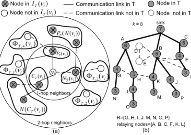
Fig. 1. (a) Classification of𝑣𝑖’s 1-hop and 2-hop neighbors, and (b) an
example of slot assignment, where the number in a circle is the node’s slot.
Definition 1. Given a node𝑣𝑖 and a data collection tree𝑇 in
𝐺, we define 𝑃𝑇(𝑣𝑖) as the set of 𝑣𝑖’s parent in𝑇 , 𝐶𝑇(𝑣𝑖) as
the set of𝑣𝑖’s children in𝑇 , 𝑁(𝑣𝑖) as the set of 𝑣𝑖’s neighbors
in 𝐺, and 𝑁𝑇(𝑣𝑖) = 𝑁(𝑣𝑖) − 𝑃𝑇(𝑣𝑖) − 𝐶𝑇(𝑣𝑖) (i.e., 𝑣𝑖’s
neighbors excluding𝑣𝑖’s parent and children in𝑇 ). We define
the interference set of𝑣𝑖 with respect to 𝑇 as:
𝐼𝑇(𝑣𝑖) = 𝑁(𝑣𝑖) ∪ 𝑁(𝐶𝑇(𝑣𝑖)) ∪ 𝑃𝑇(𝑁(𝑣𝑖)) − {𝑣𝑖}. (1)
Eq. (1) contains 𝑣𝑖’s direct interference set (𝑁(𝑣𝑖)) and
indirect interference set(𝑁(𝐶𝑇(𝑣𝑖)) ∪ 𝑃𝑇(𝑁(𝑣𝑖))). The first
set contains all𝑣𝑖’s 1-hop neighbors. However, the second set
may not contain all𝑣𝑖’s 2-hop neighbors. Nodes in𝑣𝑖’s 2-hop
neighbors but not in𝑁(𝐶𝑇(𝑣𝑖)) ∪ 𝑃𝑇(𝑁(𝑣𝑖)) can be divided
into four subsets:
Φ𝑇,1(𝑣𝑖) = 𝑁𝑇(𝑁𝑇(𝑣𝑖)) − 𝐼𝑇(𝑣𝑖)
Φ𝑇,2(𝑣𝑖) = 𝐶𝑇(𝑁𝑇(𝑣𝑖)) − 𝐼𝑇(𝑣𝑖)
Φ𝑇,3(𝑣𝑖) = 𝐶𝑇(𝑃𝑇(𝑣𝑖)) − 𝐼𝑇(𝑣𝑖)
Φ𝑇,4(𝑣𝑖) = 𝑁𝑇(𝑃𝑇(𝑣𝑖)) − 𝐼𝑇(𝑣𝑖). (2)
Fig. 1(a) shows how we divide𝑣𝑖’s 1-hop and 2-hop neighbors
in an abstract way. Considering node𝐾, Fig. 1(b) shows an
example, where𝐺 ∈ Φ𝑇,1(𝐾), 𝐿 ∈ Φ𝑇,2(𝐾), 𝐽 ∈ Φ𝑇,3(𝐾),
and𝐹 ∈ Φ𝑇,4(𝐾). We see that data reporting from 𝑁 to 𝐺
and from𝑀 to 𝐾 can coexist without interference. Similarly,
reception at 𝐿, 𝐽, and 𝐹 is also interference-free. Note that
interference should be decided at the receiver side, not the sender side. Therefore, all 𝐺, 𝐿, 𝐽, 𝐹 , and 𝐾 can use the
same slot (4). The following theorem proves that Eq. (1) gives the tightest interference set.
Theorem 1. Givenℛ and a tree 𝑇 in 𝐺, a slot assignment
for data collection is interference-free iff for each pair of𝑣𝑖
and𝑣𝑗 such that𝑣𝑗∈ 𝐼𝑇(𝑣𝑖), we have 𝑠𝑖∕= 𝑠𝑗.
Proof: To prove the if part, we will show that if an
assignment achieves 𝑠𝑖 ∕= 𝑠𝑗 for each pair of 𝑣𝑖 and 𝑣𝑗
such that 𝑣𝑗 ∈ 𝐼𝑇(𝑣𝑖) then the assignment is
interference-free. Consider each 𝑣𝑗 in 𝑣𝑖’s 1-hop and 2-hop neighbors
(refer to Fig. 1(a)). It is clear that no𝑣𝑗 ∈ 𝐼𝑇(𝑣𝑖) will cause
interference with𝑣𝑖. For each 𝑣𝑗 ∈ Φ𝑇,𝑞(𝑣𝑖), 𝑞 = 1 . . . 4, we
will show that if𝑠𝑗= 𝑠𝑖, the reception activities of𝑣𝑖and𝑣𝑗
will not suffer from interference (there is no need to consider
their transmission activities because this will be examined when considering their parents). Without loss of generality, we consider any child𝑣𝑐 of𝑣𝑗; there are two cases.
1. If 𝑣𝑐 is 1-hop away from 𝑣𝑖, then 𝑣𝑗 ∈ 𝑃𝑇(𝑁(𝑣𝑖)) ⊆ 𝐼𝑇(𝑣𝑖), which implies 𝑠𝑖 ∕= 𝑠𝑗. So, 𝑣𝑗 will not choose the
same slot as 𝑣𝑖.
2. If 𝑣𝑐 is 2-hop or above away from 𝑣𝑖, then 𝑣𝑐’s signal
cannot be heard by 𝑣𝑖. So, 𝑣𝑖 will not be interfered by 𝑣𝑐’s
transmission.
To prove the only if part, we show that if an assignment for
𝑇 is interference-free, for each pair 𝑣𝑖 and𝑣𝑗 such that𝑣𝑗 ∈
𝐼𝑇(𝑣𝑖), we have 𝑠𝑖∕= 𝑠𝑗. This part is proved by contradiction.
Assume that there is a pair of𝑣𝑖and𝑣𝑗 such that𝑣𝑗∈ 𝐼𝑇(𝑣𝑖)
and𝑠𝑖= 𝑠𝑗. By Eq. (1),𝑣𝑗 may fall in three subsets.
1. If 𝑣𝑗 ∈ 𝑁(𝑣𝑖), 𝑠𝑖 = 𝑠𝑗 will lead to direct interference,
which is a contradiction.
2. If 𝑣𝑗 ∈ 𝑁(𝐶𝑇(𝑣𝑖)), 𝑠𝑖 = 𝑠𝑗 will cause reception at the 𝑣𝑗 side being interfered by the transmission of 𝑣𝑖’s children,
a contradiction.
3. If 𝑣𝑗 ∈ 𝑃𝑇(𝑁(𝑣𝑖)), 𝑠𝑖 = 𝑠𝑗 will cause reception at the 𝑣𝑖 side being interfered by the transmission of𝑣𝑗’s children,
a contradiction.
To address goal (ii), given a tree 𝑇 , we then define the
latency of data collection along𝑇 . The data collection latency 𝐿𝑇(𝑣𝑖, 𝑣𝑗) along a tree link (𝑣𝑖, 𝑣𝑗) is the number of slots from 𝑣𝑖 collecting a report from a child to 𝑣𝑖 forwarding them to 𝑣𝑗, i.e., 𝐿𝑇(𝑣𝑖, 𝑣𝑗) = (𝑠𝑗 − 𝑠𝑖) mod 𝑘. Similarly, the data
collection latency along a tree path𝑃 = 𝑣𝛼1 → 𝑣𝛼2→ ⋅ ⋅ ⋅ → 𝑣𝛼𝑚 is defined as𝐿𝑇(𝑃 ) = 𝐿𝑇(𝑣𝛼1, 𝑣𝛼2) + 𝐿𝑇(𝑣𝛼2, 𝑣𝛼3) +
⋅ ⋅ ⋅ + 𝐿𝑇(𝑣𝛼𝑚−1, 𝑣𝛼𝑚). Finally, the data collection latency of
𝑇 is defined as 𝐿𝑇 = max{𝐿𝑇(𝑃 )∣ each path 𝑃 from a leaf
of 𝑇 to sink}. For example, in Fig. 1(b), 𝐿𝑇(𝐾, 𝐵) = 2,
𝐿𝑇(𝑃 = 𝐾 → 𝐵 → 𝑠𝑖𝑛𝑘) = 3, and 𝐿𝑇 = 4.
Definition 2. Given network𝐺 = (𝑉, 𝐸), data collection set ℛ, and 𝑘 available slots, the wake-up scheduling problem is
to find a subtree𝑇 in 𝐺 and a slot assignment for each node in
𝑇 which is interference-free and the overall reporting latency
𝐿𝑇 is as small as possible.
III. DISTRIBUTEDWAKE-UPSCHEDULINGALGORITHM Based on the definition in Eq. (1), we propose a distributed algorithm. It contains two phases. The first tree-formation
phase is to form a subtree𝑇 to connect all nodes in ℛ. The
second slot-allocation phase is to find an interference-free slot for each node in 𝑇 with low latency 𝐿𝑇.
Tree-formation phase: Each node attempts to join the network using its interference set as the metric. Note that first
𝑇 will include all nodes and then some nodes may truncate
themselves from𝑇 later on.
1. To initiate a new data collection task, the sink floods a
FORM TREE(ℛ) packet to the whole network.
2. On receipt of the FORM TREE(ℛ) packet, each node 𝑣𝑖 will repeatedly broadcast a HELLO packet containing its
parent (if it already has one) and its 1-hop neighbor set to its 2-hop neighbors for a period of time. It will also collect these information from its 2-hop neighbors.
3. Each node𝑣𝑖will try to find a node as it parent from those
852 IEEE COMMUNICATIONS LETTERS, VOL. 13, NO. 11, NOVEMBER 2009
ˀˉ˃
ˇ˃˃ ˉ˃˃ ˋ˃˃ ˄˃˃˃ ˄˅˃˃ ˄ˇ˃˃ ˄ˉ˃˃
˃
DSA Tx-based Ours DSA Tx-based Ours
-60 -40 -20 0 20 40 60 80 100 120 140 160 180 400 600 800 1000 1200 1400 1600 |V| 0 40 80 120 160 200 240 280 320 In te rf er e n ce nei ghbor s 0 10 20 30 40 50 60 0.1 0.2 0.3 0.4 0.5 0.6 0.7 0.8 0.9 1 r 10 20 30 40 50 60 70 In te rf e rence ne ig hbor s (a) (b) LT LT
Fig. 2. (a)𝐿𝑇 vs.∣𝑉 ∣ (𝑘 = 128 slots). (b) 𝐿𝑇 vs.𝑟 (n=1000).
candidates,𝑣𝑖will choose the one which causes the least value
of (𝑑𝑒𝑝𝑡ℎ(𝑃𝑇′(𝑣𝑖)), ∣𝐼𝑇′(𝑃𝑇′(𝑣𝑖))∣) as its parent. Note that
𝑑𝑒𝑝𝑡ℎ(𝑃𝑇′(𝑣𝑖)) can help reduce the data collection latency
and∣𝐼𝑇′(𝑃𝑇′(𝑣𝑖))∣ can help improve slot reuse. Here we give
priority to the former term. So, a pair(𝑎, 𝑏) is considered less than a pair(𝑐, 𝑑) if 𝑎 < 𝑐 or 𝑎 = 𝑐 but 𝑏 < 𝑑. (Note that here we use𝑇′ on purpose to reflect the fact that𝑇 is now under
construction. So, here 𝐼𝑇′(𝑣𝑖) means the set of interference
nodes that𝑣𝑖 knows so far, from overheard HELLOs.)
4. After 𝑣𝑖 chooses a parent node, there are two cases. (a)
If 𝑣𝑖 ∈ ℛ, it unicasts a JOIN TREE(𝑣𝑖) packet to the sink.
(b) If𝑣𝑖 /∈ ℛ, it sets a timer Δ𝑇𝑗𝑜𝑖𝑛 and then waits for any JOIN TREE(⋅) passing it. If it helps relay any JOIN TREE(⋅),
it should join𝑇 . Otherwise, after Δ𝑇𝑗𝑜𝑖𝑛 expires, it truncates
itself from 𝑇 by sending a TRUNCATE packet to its parent
and flooding a TRUNCATE packet to its children. Note that the selection ofΔ𝑇𝑗𝑜𝑖𝑛 depends on the expected depth of𝑇 .
A too small Δ𝑇𝑗𝑜𝑖𝑛 will cause some nodes in ℛ unable to
join𝑇 . We suggest that Δ𝑇𝑗𝑜𝑖𝑛should be proportional to the
depth of𝑇 plus some guard time.
5. After receiving JOIN TREE(⋅) packets from all members
ofℛ, the sink will flood an ASSIGN SLOT(ℛ) packet to the
whole network to terminate this phase and start the next phase. Slot-allocation phase: Nodes in 𝑇 will compete for slots
in a top-down manner. A loop is used to select a node’s slot, and priority is given to nodes with larger interference sets.
1. After sending out the above ASSIGN SLOT(ℛ) packet,
the sink will assign slot𝑘−1 to itself and repeatedly broadcast
a GET SLOT(𝑠𝑖𝑛𝑘, 𝑘 − 1) packet to its 2-hop neighbors for a period of time.
2. When a node𝑣𝑖∈ 𝑇 without a wake-up slot receives a
GET SLOT(𝑣𝑗, 𝑠𝑗) from its parent node 𝑃𝑇(𝑣𝑖), it will set a
tentative variable𝑡𝑖= (𝑠𝑃𝑇(𝑣𝑖)− 1).
3. Then, 𝑣𝑖 will try to find a candidate slot 𝑠𝑖 as follows.
(a) Let 𝑆 ⊆ 𝐼𝑇(𝑣𝑖) be the set of nodes in 𝑣𝑖’s interference
set that have already decided their wake-up slots (this can be collected from GET SLOT(⋅) packets). (b) If slot (𝑡𝑖 mod 𝑘)
conflicts with any slot owned by nodes in𝑆, decrement 𝑡𝑖by
1 and repeat step (a); otherwise, go to step 4.
4. Node 𝑣𝑖 then sets 𝑠𝑖 = 𝑡𝑖 mod 𝑘 as a candidate
slot and repeatedly broadcasts a COMPETE SLOT(𝑣𝑖, 𝑠𝑖)
packet for a period of time Δ𝑇𝑐𝑜𝑚𝑝𝑒𝑡𝑒. Here, Δ𝑇𝑐𝑜𝑚𝑝𝑒𝑡𝑒
should be large enough for each node to disseminate/collect information to/from its 1-hop and 2-hop neighbors. We suggest
that Δ𝑇𝑐𝑜𝑚𝑝𝑒𝑡𝑒 should be proportional to the square of the
maximum degree of the WSN.
5. DuringΔ𝑇𝑐𝑜𝑚𝑝𝑒𝑡𝑒, if𝑣𝑖 receives any REJECT SLOT(𝑠𝑖)
packet, 𝑣𝑖 must go back to step 3 by decrementing 𝑡𝑖 by
1 and find another candidate slot. After Δ𝑇𝑐𝑜𝑚𝑝𝑒𝑡𝑒, if no
REJECT SLOT(⋅) packet is received, 𝑣𝑖 will confirm using
𝑠𝑖 by repeatedly broadcasting GET SLOT(𝑣𝑖, 𝑠𝑖) packets to
its 2-hop neighbors for a period of time.
6. When𝑣𝑖receives a COMPETE SLOT(𝑣𝑗, 𝑠𝑗) packet from 𝑣𝑗 and 𝑠𝑗 = 𝑠𝑖, 𝑣𝑖 has a higher priority over𝑣𝑗 if (i)𝑣𝑖 has
already broadcasted GET SLOT(𝑣𝑖, 𝑠𝑖) or (ii) 𝑣𝑖 has already
broadcasted COMPETE SLOT(𝑣𝑖, 𝑠𝑖) and∣𝐼𝑇(𝑣𝑖)∣ > ∣𝐼𝑇(𝑣𝑗)∣
or (∣𝐼𝑇(𝑣𝑖)∣ = ∣𝐼𝑇(𝑣𝑗)∣ ∧ (𝑖 > 𝑗)). If so, 𝑣𝑖 unicasts a
REJECT SLOT(𝑠𝑗) to 𝑣𝑗; otherwise, 𝑣𝑖 will receive a
RE-JECT SLOT(⋅) packet in step 5 and then goes to step 3.
IV. SIMULATIONRESULTS ANDCONCLUSIONS We randomly deploy 𝑛 nodes in a 200 × 200 𝑚2 region.
Each node has a transmission range of20 𝑚, and there are 𝑘 = 128 available slots. Let 𝑟 = ∣𝑅∣∣𝑉 ∣ be the ratio of data collection nodes. Note that when𝑟 = 1.0, the problem is equivalent to
the convergecast problem [3]. We compare our scheme against
DSA [3] and Tx-based scheme [5], both of which use a BFS
tree to connect all nodes. In DSA, each node has a reception slot by considering 2-hop neighbors as its interference set. In Tx-based scheme, each node has a transmission slot by considering its 1-hop neighbors, its siblings, and the children of its neighbors as its interference set. Fig. 2(a) compares
𝐿𝑇 (denoted by lines) under various numbers of ∣𝑉 ∣ when 𝑟 = 1.0. Our scheme has around 62.60% and 32.28% less
latency than DSA and Tx-based scheme, respectively. This is because the size of our interference set (i.e., 𝐼𝑇(𝑣𝑖)) is only
about 42.56% and 83.12% of that in DSA and in Tx-based scheme, respectively, as shown in Fig. 2(a) (denoted by bars). Fig. 2(b) investigates the impact of𝑟 on 𝐿𝑇. It shows that𝐿𝑇
will increase as𝑟 increases, but our increasing rate, contributed
by Eq. (1), is relatively slower.
To conclude, this paper considers a data collection scenario in WSNs which has less strict constraints on interference. We then propose an efficient scheduling and verify it via simulations. Our scheme can only handle one data collection task. When there are multiple tasks, one direct extension is to union all their sets ℛs and regard them as one task. A
future research direction is how to schedule multiple tasks at the same time in an efficient way.
REFERENCES
[1] G. Lu, B. Krishnamachari, and C. S. Raghavendra, “An adaptive energy-efficient and low-latency MAC for data gathering in wireless sensor networks,” in Proc. IEEE Int’l Parallel and Distributed Processing Symp., 2004, pp. 224–231.
[2] A. Keshavarzian, H. Lee, and L. Venkatraman, “Wakeup scheduling in wireless sensor networks,” in Proc. ACM Int’l Symp. Mobile Ad Hoc Networking and Computing, 2006, pp. 322–333.
[3] M.-S. Pan and Y.-C. Tseng, “Quick convergecast in ZigBee beacon-enabled tree-based wireless sensor network,” Computer Comm., vol. 31, no. 5, pp. 999–1011, 2008.
[4] L. Paradis and Q. Han, “TIGRA: timely sensor data collection using dis-tributed graph coloring,” in Proc. IEEE Int’l Conf. Pervasive Computing and Communications, 2008, pp. 264–268.
[5] H. Wu, Q. Luo, and W. Xue, “Distributed cross-layer scheduling for in-network sensor query processing,” in Proc. IEEE Int’l Conf. Pervasive Computing and Communications, 2006, pp. 180–189.