Design and Analysis of a New Self-Routing Network
Tsern-Huei LeeAbstract- A new self-routing network constructed from the sorting and the routing cells is proposed. The complexity of the new network is roughly twice as much as that of a pure banyan network. The new network can be viewed as an implementation of the load-sharing network [6] which requires a very simple management. Its performance under uniform and nonuniform traffic models is analyzed for the unbuffered case. It is found that a higher degree of nonuniformity results in a better performance for certain form of nonuniform traffic matrices. Simulations are performed to obtain the normalized throughputs and mean packet delays for the single-buffered case. Different from single- buffered pure banyan networks [lo], the mean delay of high- traffic packets is smaller than that of low-traffic packets for a particular form of nonuniform traffic matrices. In addition to performance improvement, the new network is easy to diagnose. Some variations of the proposed network are also studied.
I. INTRODUCTION
ELF-ROUTING networks are being considered to in-
S
terconnect processing elements and memory modules in multiprocessor systems and to construct the switching fab- ric of future telecommunications networks. The normalized throughput, i.e., the average number of packets received by an outlet per network cycle, is often chosen to be the performance measure of this type of networks in a packet switching environ- ment. Since many self-routing networks including the omega network, the indirect binary n-cube network, the baseline network, and the regular SW banyan network with spread andfan-out of 2 were proved [ l ] to be topologically equivalent, we will not distinguish these terms in this paper.
Under the uniform traffic model, the normalized throughput of an unbuffered banyan network can be easily computed by a simple iterative algorithm [2]. By uniform traffic model, it is meant that all inlets have independent and identical input rates and each outlet is equally likely to be the destination of any packet. It was shown in [2] that banyan networks are more cost-effective than crossbars for processor-memory interconnection in a large multiprocessor system. However, due to internal blocking, the performance of large banyan networks may not be acceptable. One way to avoid internal blocking is to place a Bather’s bitonic sorter [12] in front of the banyan network. The universality of the Batcher-banyan network was proved in [4]. Unfortunately, the complexity of a Batcher-banyan network is much higher than that of a pure banyan network and, moreover, a single fault occurred in Paper approved by the Editor for Communication Switching of the IEEE Communications Society. Manuscript received June 20, 1989; revised October 9, 1990. This work was supported in part by the National Science Council, Republic of China, under Contract NSC80-0404-E009-40.
The author is with the Department of Communication Engineering and Center for Telecommunications Research, National Chiao Tung University, Hsinchu, Taiwan 30050, Republic of China.
IEEE Log Number 9105168.
the bitonic sorter could be disastrous to the network. Other variations such as multiplane [5], load-sharing [6], and single- buffered [7] banyan networks were proposed to achieve a better performance.
The uniform traffic assumption may not be true for a real- world system. In [8] Lee analyzed the performance degradation of unbuffered banyan networks caused by nonuniform traffic flow. Garg and Huang [9] and Lee [lo] investigated the single-buffered networks. Some useful forms of nonuniform traffic matrices were studied in [8]-[lo] and it was found that a higher degree of nonuniformity results in a more serious performance degradation. The assumption of independent and identical input rates remains in [8]-[lo].
In this paper, we propose a new self-routing network and evaluate its performance under uniform and nonuniform traffic models for both unbuffered and single-buffered cases. The new self-routing network is constructed from two basic cells, the sorting cell and the routing cell. The sorting cell is actually a bitonic sorter with two inputs and the routing cell is a 2 x 2 switching element of a banyan network. The proposed new self-routing network can be considered as an implementation of the load-sharing banyan network [6] which is easy to
diagnose and requires a very simple operation.
The structure of the new self-routing network is detailed in Section 11. The normalized throughput of the unbuffered new self-routing network is evaluated in Section 111. In Section IV,
the performance of single-buffered networks is considered. Since accurate analytical models for single-buffered banyan networks are very complicated [lo], simulations are performed to obtain the performance. Several variations of the proposed network are discussed in Section V. Finally, some conclusions are drawn in Section VI.
11. THE NEW SELF-ROUTING NETWORK
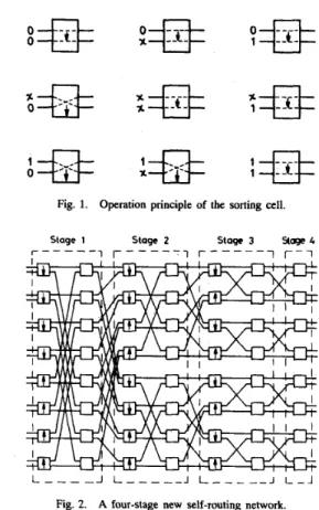
As mentioned before, the sorting and the routing cells are the two building blocks of the proposed new self-routing network. The operation principle [4] of the sorting cell is shown in Fig. 1, in which the symbol x represents an inactive input. A four-stage new self-routing network is illustrated in Fig. 2. Basically, the new self-routing network is constructed by inserting sorting cells before routing cells in each stage, except the last one, of a banyan network.
For an n-stage new self-routing network, the routing cells
in each stage, except the last one, are partitioned into 2n-2 groups, each group consists of a pair of routing cells. If binary sequences of length n - 1 are used to represent the routing cells in each stage from the top, then two routing cells in stage i. 1
5
i5
n - 1, are in the same group if their representations differ only in the ( n - i)th bit, counted from right to left. 009&6778/92$03.00 0 1992 lEEE172 IEEE TRANSACTIONS ON COMMUNICATIONS, VOL. 40, NO. 1, JANUARY 1992
A#
;#
;e
Fig. 1. Operation principle of the sorting cell.
Stage 1 Stage 2 Stage 3 %age 4 r - - - i r - - - i r - - - i r - i
L
_ _ _ _
J L_ _ _ _ _
J L_ _ _ _ _
J L - JFig. 2. A four-stage new self-routing network.
Notice that two routing cells belonging to the same group share their loads. The four input links (to sorting cells) of a pair of routing cells of the same group should be considered together. For convenience, the two upper (or lower) input links, one for each sorting cell, are called the upper (lower) input links of the pair of routing cells. Similarly, the four output links of a pair of routing cells are also partitioned into the upper output links and the lower output links. Blocking occurs only when three or four active packets received by the four input links are to be routed simultaneously to the upper or the lower output links. Therefore, the new self-routing network can be viewed as an implementation of the load-sharing banyan network [6]. The
implementation is simple because the connections inside the two building blocks are both bit-controlled and hence high- speed switching is achievable. Besides, the implementation can provide tlie maximum number of alternate paths between each inlet-outlet pair [6].
Since the complexity of a sorting cell is roughly the same as that of a routing cell, the complexity of the new self- routing network is about twice as much as that of a pure banyan network. Furthermore, the fault diagnosis techniques developed in [ll] can be directly applied to the proposed
networks because the valid states of the sorting and the routing cells are identical, i.e., both allow only straight or cross connection. For example, a link stuck at fault can be detected by the existence of faulty paths and the faulty link can be located by finding the common link traversed by two faulty paths. In addition to self-routing and easiness of fault
diagnosis, the new network obviously has a better fault tolerant capability than a pure banyan network because any inlet-outlet pair can be connected via different paths.
111. PERFORMANCE FOR UNBUFFERED NETWORKS
Consider an n-stage new self-routing network. Notice that the connection pattern between the sorting cells and the louting cells in each stage has the property that the upper as well
as the lower output links of a pair of routing cells in stage i, 1
5
i5
n-
2, are the upper or the lower input links of another pair of routing cells in stage i+
1. Because of load-sharing, the upper (and the lower) output links of a pair of routing cells are related.As
usual, the normalized throughput is chosen to be the performance measure for the unbuffered networks. We assume for simplicity that all inlets have independent and identical input rates denoted by p. An important and useful observation is that the upper input links are independent of the lower input links for any pair of routing cells. Therefore, recursive formulae can be derived to compute the normalized throughput under uniform and nonuniform traffic models for unbuffered networks. In the following, we study the uniform traffic model first.A. Uniform Traffic Model
Consider a pair of routing cells in stage 1. Let h ( 0 ) =
(ho(O), h1(0), hz(0)) denote the probability distribution of the
upper (and the lower) inlets, i.e., h;(O), z = 0 , 1 , 2 , is equal to the probability that the upper (or lower) inlets receive totally
i active packets at the beginning of a cycle. Given the input rate p, we have ho(0) = (1
-
p)',h1(0) = 2p(l-
p ) , and hz(0) = p2. Consider a pair of routing cells in stage k, 15
( g o ( k ) , g 1 ( k ) , 9 2 ( k ) ) denote the probability distributions of the upper and the lower input links, respectively. Further, let a and b represent the probabilities that a packet arriving at an input link of the pair of routing cells is to be routed to one of the upper output links or one of the lower output links, respectively. Define three functions as follows:
k
5
n - 2. Let h(k) =(h0(k),hi(k),h2(k))
and g ( k ) =2 2
Z E R O ( h ( k ) , g ( k ) ; a , b) =
2
h i ( k ) g j ( k ) b i + j ,i = O j = O
2 2
Clearly, if h(k
+
1) = (ho(k+
I),
h l ( k+
I),
hz(k
+
1))denotes the probability distribution of the upper output links of the pair of routing cells, then ho(k
+
1) = Z E R O ( h ( k ) , g ( k ) ; a, b), h l ( k+
1) = O N E ( h ( k . ) , g(k); a, b), and hz(k+
1) = T W O ( h ( k ) , g ( k ) ; a, b). For convenience, let h(k+
1) = N E X T ( h ( k ) , g ( k ) ; a, b) denote this relationship. Also, letS u ( n , h ( 0 ) ) represent the normalized throughput. Then we have
new network '"I
S u ( n , h ( 0 ) ) = S u ( n - 1 , h ( 1 ) ) =
. . .
= S u ( 2 , h(n - 2 ) ) where h(z) = NEXT(h(i - l ) , h(z - 1 ) ; 1 / 2 , 1 / 2 ) , 15
z5
n - 2. The boundary situation is given by S u ( 2 , h(n - 2 ) ) =
S u ( 1 , h(n - 1 ) ) = 1 / 2 [ h l ( n - 1 )
+
3/2 h2(n - l ) ] , where In a real-world system, packets may not be directed uni- formly over all outlets. Therefore, it is worthwhile to alsounder some useful forms of nonuniform traffic matrices. In the 0 2 0 4 0 6 O B 1
evaluate the performance of the new self-routing network h(n - 1 ) = NEXT(h(n - 2 ) , h ( n - 2 ) ; 1 / 2 , 1 / 2 ) .
following, we consider two forms of nonuniform traffic ma- input rate
trices which were used to study the performance degradation
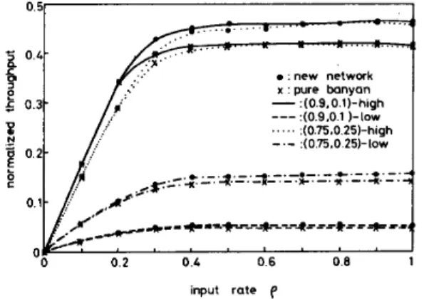
of pure banyan networks in [8]-[lo]. Fig. 3. Normalized throughput under nonuniform traffic of Form I.
B. Nonuniform Traffic Matrices: Form I
ested in looks like
The first form of nonuniform traffic matrices we are inter-
T n ( k ) = [ V n - k ( m l ) V n - k ( m Z ) ' ' ' k k( m L ( k ) ) ]
where m,'s are nonnegative numbers between zero and one, L ( k ) = 2 k ,
E:::)
m, = 1, and V,-k(m) is a uniform matrix of order 2" x 2n-k with row sum equals m. Notice that k = 0 corresponds to the uniform traffic model.The outlets of the new self-routing network under a nonuni- form traffic matrix of Form I can be partitioned into 2k groups,
each group consists of 2n-k elements. Let the address of each outlet be represented by a binary sequence a n - l a , - ~ . . ' U O
of length n. Then group 2, 1
5
a5
2'", consists of outlets whose addresses satisfy the condition that u,-la,-p . . . ak is the binary representation of the integer z - 1. Besides, the traffic matrix means that each packet is destined to group zwith probability m,.
Let h(0) = (ho(0). h 1 ( 0 ) , h z ( 0 ) ) have the same meaning as we defined in part A. Also, let S ( n , k,m,h(O)) denote the normalized throughput. For convenience, m =
( m l , m2,
. . . ,
m L c k ) ) is called the parameter vector. Beforederiving the recursive formula for S ( n , k , m, h(O)), let us define an induced matrix T;-,(k - 1 ) of the traffic matrix T,(k) as follows:
(
)I
1
T A - l ( k - l ) = - [ k k( m L ( k ) / Z + l ) ' ' ' v n - k m L ( k ) B k
where Bk = ~ f ~ ~ { k ) / z + l m,. It is noted that T A P l ( k - 1 ) is
the traffic matrix for packets whose destination is located in the lower half of the network. Let A k = 1 - B k , then A k and B k represent the probabilities that the destination of a packet
is located in the upper or the lower half, respectively. The recursive formula for S ( n , k , m, h ( 0 ) ) is given below. S ( n , k , m, h(0)) =
S u ( n , h ( 0 ) ) IC = 0 ,
1 / 2 [ S ( n - 1 , k - l l " , h ( l ) )
{
+
S ( n - l , k - l , m " , h ' ( l ) ) ] k<
n,where m: = m,/Ak and m y = m m + L ( k ) p / B k , l
5
a5
L ( k ) / 2 . The vectors h ( 1 ) and h ' ( 1 ) are equal to NEXT(h(O),h(0); A k , B k ) and NEXT(h(O), h(0); Bkl AB), respectively. The boundary situation is given by
S ( I , ~ , m , z ) = 1 / 2 [ z l
+
( 2 - m: - m ; ) z z ] where m = (m1,mz) and z = ( z o , z l , z 2 ) .In this paper, all numerical results are performed for six- stage networks. Fig. 3 shows the normalized throughputs
against input rate p for k = 1 and ( m l , mz) = (0.5, O S ) , (0.75, 0.25), or (0.9,O.l). According to the numerical results, a larger improvement is achieved at a smaller degree of nonuniformity. The maximal improvement is about 24% under uniform traffic
model with p = 1.
C. Nonuniform Traffic Matrices: Form I1
analyze looks like
The second form of nonuniform traffic matrices we will
I
&-1(m1)
I
D , - l ( m z )[
~ , - 1 ( m 2 ) ~ ~ " - 1 ( m 1 )I
Tn (IC) = - - - - - -
where ml and m2 are nonnegative numbers between zero and
one satisfying ml +ma = 1, and D,-l(m) is a 2'&-' x 2"-l matrix with all its elements equal m/ (2"-'). The boundary situations are given as
[:;
21.
Tn(0) = [ D n ( l ) ] and T l ( 1 ) =
For a new self-routing network under a nonuniform traffic matrix of Form 11, the inlets and outlets are both partitioned into two groups. Group 1 and group 2 consist of inlets (or outlets) located in the upper and the lower halves of the network, respectively. A packet originated at an inlet of group
i ( i = 1 , 2 ) is destined for outlets of group i with probability
ml and is destined for outlets of group j ( j = 1,2 and j
#
i )with probability m2.
It is not hard to see that the traffic flow becomes uniform after stage 1. Therefore, the normalized throughput can be easily computed by the recursive formula derived in part A
once the probability distribution h ( 1 ) of the upper and the lower input links of a pair of routing cells in stage 2 is determined. For this case, the upper inlets and the lower inlets
174 IEEE TRANSACTIONS ON COMMUNICATIONS, VOL. 40, NO. 1, JANUARY 1992
0:' 0.2 ' ' 0.4 ' ' 0.6 ' ' 0.8 ' '
I
input rate f
Fig. 4. Normalized throughput under nonuniform traffic of Form 11.
of a pair of routing cells in stage 1 are the two inlets of the upper or the lower sorting cell, respectively. Consider the upper inlets of a pair of routing cells in stage 1. Let
zo(i),,zl(i), and z 2 ( i ) , O
5
i
5
2, be equal tomi,
im1d-',and
(
a ) m $ k 2 , respectively. That is, zj(i) is the probability that exactly j out of the i packets received by the upper inlets are destined for the upper output links. Similarly, let denote the corresponding probabilities of the lower inlets. Then we haveYO(A = &Yl(j) = jm274-l7 and Y2(A = (;)m;mr2
2 2 2 2 hl(1) = hi(o)hj(o)[zl(i)Yo(j)
+
zo(i)Yl(j)l, h2(1) = i=o j = o 2 2 h Z ( W j ( 0 ) {z2(4+
zl(i)[Yz(A+
Yl(d1+
zo(i)Y2(j)). i=o j = oLet S ( n , m, h(0)) denote the normalized throughput of an n-stage new self-routing network under a nonuniform traffic matrix of Form 11. Then S ( n , m, h(0)) can be computed by
S(n,m,h(O)) = Su(n
-
L h ( 1 ) )where Su(n - 1, h(1)) is the normalized throughput under the uniform traffic model.
In Fig. 4, one can see that the normalized throughput of the new self-routing network is insensitive to the degree of nonuniformity
.
However, it is interesting to note that a higher degree of nonuniformity of Form I1 yields a better perfor- mance. The reason is that a higher degree of nonuniformity results in a smaller blocking probability in stage 1. Therefore, a larger improvement can be achieved for a higher degree of nonuniformity. The maximal improvement is about 63% for (ml,mz) = (0.9, 0.1) which also occurs when p = 1.Iv. PERFORMANCE FOR SINGLE-BUFFERED NETWORKS
Buffers can be added to the sorting cells in stages 1 to n
-
1 and to the routing cells in stage n to enhance the: new network x : pure banyan -. .(0.9.O.l)-high .(0.9.0.1 )-low :(0.75.0.25)-high -.- :(o.~75.0.25)-low ---. ... input rate f
Normalized throughputs under nonuniform traffic of Form I. Fig. 5 .
performance. We will study single-buffered networks in this section. Analytical models similar to those adopted in [6] and [ 101 can be used to obtain performance estimates. However, as discussed in [lo], the results obtained for a four-stage banyan network by such models could deviate from simulation values by about 10% due to the dependence among buffers in different stages. Therefore, rather than using over simplified analytical models, we perform simulations to find the performance. In our simulations, packets are generated at the end of network cycles. A packet generated by an inlet is lost if that inlet's buffer is full. Furthermore, a packet can advance at most one stage per network cycle.
Consider nonuniform traffic matrices of Form I discussed in the last section with
k
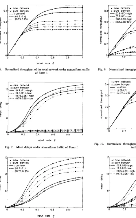
= 1. For convenience, packets whose destinations located in the upper or the lower halves are called the high-traffic packets and the low-traffic packets, respectively. Figs. 5 -8 show the normalized throughputs and the mean delays of the high-traffic packets and the low- traffic packets for six-stage networks. One can see from Fig. 5 that the ratio of the high-traffic throughput to the low-traffic throughput is equal to m1/m2, which is a consequence of the traffic pattern. In Fig. 6, the normalized throughput of the total network is equal to half of the sum of tht high-traffic and low-traffic throughputs. In Fig. 7, the mean delay represents the average number of network cycles a packet spends inside the network. The mean delay of the total network illustrated in Fig. 8 is equal to (ShDh+
SlDl)/(Sh+
Sl) where Sh( 4 )
and
Dh
(01) represent, respectively, the throughput and mean delay of high-traffic (low-traffic) packets. The new self-routing network clearly has a better performance than the pure banyan network. The maximal improvement is about 11% for normal- ized throughput and 5% for mean delay when (m1,mz) = (0.9, 0.1) with p = 1.Now consider nonuniform traffic matrices of Form 11. The inlets and the outlets are both partitioned into two groups as we did in Section 111. A packet originated at an inlet of group i ( i = 1,2) is called a high-traffic packet or a low- traffic packet according to whether its destination is located in group i or group j ( j = 1 , 2 and j
#
2 ) . The normalizedthroughputs and mean delays of the high-traffic packets and the low-traffic packets of six-stage networks are plotted in
0 4 - 0.3- 0 2- 0.1-
.
. new network x : pure banyan-
: uniform i . , ' _ . _ . * . ......
... ., ... O F ' ' ' ' ' ' ' ' ''
0.2 0 . 4 0.6 0 8 .: new network 0.8- x:pure banyan -:(O 9.0.1)-high ... * . . . . ., ...',.
0 . 2 0 . 4 0.6 0 8input rate f input rate f
Fig. 6. Normalized throughput of the total network under nonuniform traffic Fig. 9. Normalized throughputs under nonuniform traffic of Form I1 of Form I. :new network x : pure banyan -- :(0.9,0.1) -high
---
:(0.9.0 1)-low - ... :(0.75.0.25)-high :(075.0.25)-IOw 0.2 0 . 4 0.6 0 8 1 input rate pMean delays under nonuniform traffic of Form I. Fig. 7. 12r : new network x : pure banyan
-- -
. . ..
. new network1
"0 0 2 0 4 0 6 0 8 1 input ratee
Fig. 10. Normalized throughput of the total network under nonuniform traffic of Form 11.
input rate f' input rate f
Fig. 8. Mean delay of the total network under nonuniform traffic Fig. 11. Mean delays under nonuniform traffic of Form 11. of Form I.
It is interesting to note that, different from the results for single-buffered banyan network [9], [lo], the mean delay of the high-traffic packets is close to but smaller than that of the
low-traffic packets for our proposed network under nonuniform traffic matrices of Form 11. This phenomenon can be explained by an example. Consider the case when ml = 0.75 and m2 =
0.25 with p = 1. The buffers in stage 1 are always nonempty for this example. Besides, it is very likely that three of the four Figs. 9-12. Again, the ratio of the high-traffic throughput to
the low-traffic throughput is equal to m1/m2 and the new self-routing network performs better than the pure banyan network. Similar to the unbuffered networks, a higher degree of nonuniformity results in a better performance. The maximal improvement is about 78% for normalized throughput and 13% for mean delay when ( m l , m 2 ) = (0.9, 0.1) with p = 1.
176 IEEE TRANSACTIONS ON COMMUNICATIONS, VOL. 40, NO. 1, JANUARY 1992
p
U TI CE
12 a : new network x : Dure banvan *---U-- ~ , , , , . .. .* . ."..'-
: uniform---
:(0.9.0.1) ... :(0.75.0.25) 10t "
'
input rate f'Fig. 12. Mean delay of the total network under nonuniform traffic of Form 11.
buffers of a pair of routing cells in stage 1 contain high-traffic packets and the other buffer contains a low-traffic packet. Under such a situation, the low-traffic packet has to contend with one of the high-traffic packets for its output link while two of the high-traffic packets can advance to the second stage if their destination buffers in stage 2 are empty. From stage 2 to stage n, the advance rates for the high-traffic packets and the low-traffic packets are roughly the same. Hence, the mean delay for low-traffic packets is larger than that of high-traffic packets.
If one compares the throughputs presented in Figs. 3 and 6 (or Figs. 4 and lo), then it can be seen that unbuffered networks outperform the single-buffered ones, except for pure banyan network under the uniform traffic model. This is due to the models we adopted. For both types of networks, new packets with unbalanced destination distribution may arrive from time to time. According to the model for unbuffered networks, a couple of packets will be blocked and lost. In other words, packets having bad destination distribution do not affect the other packets arriving in successive cycles. However, for single-buffered networks, some of these packets could be accepted and hence the bad effect is likely to last for a few cycles.
V. SEVERAL VARIATIONS
In this section, we consider three variations of the new self- routing network. For simplicity, only the unbuffered networks are studied.
A. Different Connection Pattern
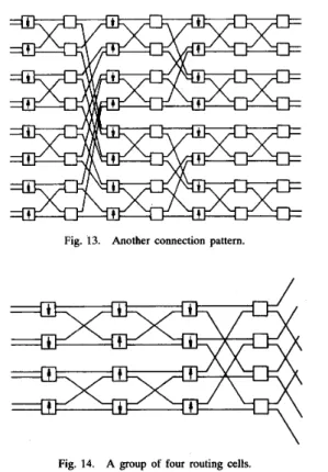
There are obviously many other possible connection patterns between the sorting cells and the routing cells in each stage. For example, Fig. 13 shows another connection pattern with a fewer number of crossovers. Notice that this connection pattern does not provide the maximum number of alternate paths between each inlet-outlet pair. For such a network, two routing cells are in the same group if and only if their binary representations differ only in the least significant bit. One can easily verify that the normalized throughput of such a network is equal to that of the network we discussed
Fig. 13. Another connection pattern.
Fig. 14. A group of four routing cells.
in previous sections under uniform traffic and nonuniform traffic of Form I. Under nonuniform traffic of Form 11, the normalized throughput can be evaluated recursively. Our ex- periments show that the connection pattern shown in Fig. 2 results in a better performance. The difference is about 25% for ( m l , m n ) = (0.9, 0.1) with p = 1.
B. More Routing Cells Share Their Loads
It was proved in [6] that 2n-t routing cells in stage
i,
15
i5
n, can share their loads so that packets will still be routed to their proper destinations. Therefore, it is possible to share the loads of four routing cells in stages 1 to n-
2. A connection pattern can be selected as follows. Four routing cells in stage i, 15
i5
n-
2, are in the same group if their binary representations differ only in the (n-
i)th and/or the (n - i - 1)th bits. Similarly, for such a network, the upper and the lower output links of a group of routing cells in stage i, 15
i5
n - 3, are the upper or the lower input links of a group of routing cells in stage i+
1. A group of four routing cells is illustrated in Fig. 14. The last two stages are the same as those of the network we studied in previous sections. Obviously, the complexity of such a variation is roughly twice of that of the network we proposed in Section 11.One can evaluate the performance of such a variation using the same approach presented in Section 111. The difference is that four (rather than two) input or output links form a group. Numerical results show that the maximal improvement in normalized throughput for a six-stage network is about 12%
under the uniform traffic model with p = 1. This improvement may not be sufficient to justify the increase in complexity.
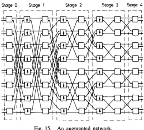
Fig. 15. An augmented network.
C. Augmented Networks
For the new self-routing network, a link fault may result in permanent disconnections between some inlet-outlet pairs. For example, suppose the upper input link of the upmost sorting cell in stage 2 is in fault. As a result, any packet to be routed through this link is blocked. Therefore, the upmost inlet can never be connected to any outlet located in the upper half. Augmented networks can be used to remove such unpleasant situations. Fig. 15 shows a four-stage augmented network. In normal operations when the network is fault-free, all the routing cells added in front of the network, i.e., in stage 0, are set to either the cross state or the straight state at the beginning of a cycle. Suppose a link fault is detected and located. An approach to remove permanent disconnections is to deliver all packets which will be routed through the faulty link in normal operation to their proper destinations via alternate paths. However, whether a packet received by a particular inlet will be routed through the faulty link depends on the destinations of other packets received by other inlets. Therefore, it may take a long time to determine the proper route for each packet. Another approach, which results in a worse performance but allows a much simpler operation is to set the routing cells in stage 0 to the cross state or the straight state with equal probability at the beginning of a cycle.
VI. CONCLUSION
We have proposed and analyzed in this paper a new self- routing network constructed from the sorting and the routing cells. The new self-routing network can be viewed as an implementation of the load-sharing banyan network which requires a simple operation and is easy to diagnose. The complexity of the proposed network is roughly twice as much as that of a pure banyan network. However, the performance improvement is significant, especially for the second form of nonuniform traffic matrices studied in this paper. Many other connection patterns between the sorting cells and the
routing cells in each stage can be arranged. The choice of connection pattern depends on whether the performance, the number of alternate paths, or the number of crossovers is of major concern. More routing cells in stages 1 to n - 2
can share their loads to obtain an even better performance. However, the complexity increases rapidly if bit-controlled routing property is a requirement. The performance of the new self-routing networks and their augmented networks having faults is currently under investigation.
REFERENCES
[ l ] C. Wu and T.Y. Feng, “On a class of multistage interconnection networks,” IEEE Trans. Comput., vol. C-26, pp. 694-704, Aug. 1980. [2] J. H. Patel, “Performance of processor-memory interconnections for multiprocessors,” IEEE Trans. Comput., vol. C-30, pp. 771 -780, Oct. 1981.
[3] C.P. Kruskal and M. Snir, “The performance of multistage intercon- nection networks for multiprocessors,” IEEE Trans. Comput., vol. C-32, pp. 1091-1098, Dec. 1983.
[4] M. J. Narasimha, “The batcher- banyan self-routing network: Universal- ity and simplification,” IEEE Trans. Commun., vol. 36, pp. 1175-1178, Oct. 1988.
(51 N. C. Huang and C. T. Lea, “Architecture of a time multiplexed switch,” in Proc. IEEE GLOBECOM, 1986, pp. 19.3.1-19.3.4.
[6] C. T. Lea, “The load-sharing banyan network,” IEEE Trans. Comput., vol. C-35, pp. 1025-1034, Dec. 1986.
[7] Y. C. Jenq, “Performance analysis of a packet switch based on single- buffered banyan networks,” IEEE Trans. Select. Areas Commun., vol. SAC-1, pp. 1014-1021, Dec. 1983.
[8] T. H. Lee, “Performance of banyan networks with inhomogeneous traffic flow,” IEE Proc., Pt. E, vol. 137, pp. 245-252, July 1990. (91 U. Garg and Y. P. Huang, “Decomposing banyan networks for perfor-
mance analysis,” IEEE Trans. Comput., vol. C-37, pp. 371-376, Mar. 1988.
[lo] T.H. Lee, “Analytic models for performance evaluation of single- buffered banyan networks under nonuniform traffic,” IEE Proc., Pt. E, vol. 138, pp. 41-47, Jan. 1991.
[ I l l T. Y. Feng and C. L. Wu, “Fault-diagnosis for a class of multistage interconnection networks,” IEEE Trans. Comput., pp. 743-758, Oct. 1981.
[12] K. E. Batcher, “Sorting networks and their applications,” in Proc. Spring Joint Comput. C o n j , 1968, pp. 307-314.
[13] L.R. Coke and G.J. Lipovski, “Banyan networks for partitioning multiprocessor systems,” in Proc. 1st Annu. Symp. Comput. Architect., 1975, pp. 21-28.
[14] D.H. Lawrie, “Access and alignment of data in an array processor,” IEEE Trans. Comput., pp. 1145-1155, Dec. 1975.
[15] M. C. Pease 111, “The indirect binary u-cube microprocessor array,” IEEE Trans. Comput., pp. 458-473, May 1977.
[16] A. Huang and S. Knauer, “Starlite: A wideband digital switch,” in Proc. IEEE GLOBECOM 1984, pp. 5.3.1-5.3.5.
Tsern-Huei Lee received the B.S. degree from National Taiwan University, Taiwan, in 1981, the M.S. degree from the University of California at Santa Barbara in 1984, and the Ph.D. degree from the University of Southern California in 1987, all in electrical engineering.
Since 1987, he has been a member of the fac- ulty of National Chiao Tung University, Hsinchu, Taiwan, Republic of China, where he is an Asso- ciate Professor of the Department of Communica- tion Engineering and a member of the Center for I
Telecommunications Research. His current research interests are in broad-band switching networks, multiple-access systems, and communication protocols.