Ž .
Optics Communications 183 2000 51–63
www.elsevier.comrlocateroptcom
Optimum configuration and design of 1480-nm pumped L-band
gain-flattened EDFA using conventional erbium-doped fiber
Tsair-Chun Liang
a,), Yung-Kuang Chen
b,1, Jing-Hong Su
b, Weng-Hung Tzeng
b,
Chiek Hu
c, Ying-Tso Lin
c, Yin-Chieh Lai
c,da
Department of Telecommunication Engineering, National Kaohsiung Institute of Marine Technology, Kaohsiung 811, Taiwan b
Institute of Electro-Optical Engineering, National Sun Yat-Sen UniÕersity, Kaohsiung 804, Taiwan c
Opto-Electronics and Systems Lab., Industrial Technology Research Institute, Chutung, Hsinchu 310, Taiwan d
Institute of Electro-Optical Engineering, National Chiao Tung UniÕersity, Hsinchu 300, Taiwan Received 18 May 2000; accepted 4 June 2000
Abstract
Ž .
We theoretically investigate optimum configurations of 1480-pumped L-band 1570–1610 nm gain-flattened
erbium-Ž .
doped fiber amplifier EDFA , using conventional erbium-doped fiber, for multi-wavelength wavelength division
multiplex-Ž .
ing WDM systems. The design criterion of L-band EDFA is to achieve the highest channel output power while keeping the differential channel output power to be F 0.7 dB among 32 digital baseband channels with low channel noise figure of
F5.5 dB. A total of nine L-band EDFA configurations are examined and compared. These configurations considered include the dual-forward, dual-backward, and different bi-directional pumping schemes, each with and without the midway optical isolator. Among all configurations, we find that the pump-passed case in forward-and-backward pumping scheme is the best amplifier configuration to offer the highest channel output power with good channel gain uniformity and moderate low noise figure. In addition, the tolerance of the ratio of first-staged EDF length to the total EDF length, and the effects of optical isolation of midway isolator, and pump power degradation on the characteristics of the best configuration are also examined. This investigation provides the EDFA configuration selection for multi-wavelength WDM L-band lightwave systems. q 2000 Published by Elsevier Science B.V.
Keywords: Optical amplifier; Erbium-doped fiber amplifier; L-band EDFA; L-band amplifier; Wavelength-division multiplexing; Optical fiber communication
1. Introduction
It is vitally important to increase the number of optical channels in wavelength division multiplexing
)
Corresponding author. Fax: q886-7-525-4499; e-mail: [email protected]
1
E-mail: [email protected].
ŽWDM transmission systems. One way to increase.
channel numbers is to narrow the channel spacing. However, it will worsen the nonlinear effects such as
Ž .
cross-phase modulation XPM or four-wave mixing
ŽFWM 1,2 , and makes accurate wavelength control. w x
of optical senders necessary. Another way to in-crease the channel number is to widen the usable wavelength bandwidth in low loss region of the used single-mode fiber.
0030-4018r00r$ - see front matter q 2000 Published by Elsevier Science B.V.
Ž .
Ž .
Erbium-doped fiber amplifiers EDFAs have
emerged as vital components for optical fiber net-works, serving a wide range of applications from
Ž .
WDM network repeaters to cable-television CATV power amplifiers and in-line amplifiers. The WDM optical fiber amplifier with a flattened amplification
Ž
region from 1530- to 1560-nm conventional band,
. w x
C-band has been well investigated 3,4 . Recently, the other new band, the long wavelength region from
Ž .
1570 to 1610-nm L-band , has also been widely
w x
investigated 5–15 through the use of a long con-ventional EDF and is very attractive for doubling of the transmission capacity. L-band EDFAs are attrac-tive for application to WDM transmission systems not only as they can increase the amplification wave-length range but they also enable us to construct a WDM transmission system using dispersion-shifted
Ž .
fiber DSF without any degradation caused by FWM
w16 .x
The amplification characteristics of L-band ED-FAs by single-staged with a single forward pumped in the 980 and 1480-nm bands have been
investi-w x
gated by H. Ono et al. 9 . Owing to the 1550-nm ASE generated by 1480-nm band pumping is the pump source of 1580-nm band amplification and the quantum conversion efficiency to 1550-nm ASE with 1480-nm band pumping is higher than that with 980-nm band pumping, the flattened gain coefficient
Žflatted signal gain to pump power ratio with 1480-.
nm band pumping were more than twice as high as those with 980-nm band pumping. On the other hand, the noise figure with 1480-nm band pumping was only degraded of 0.5 dB by compared with those for 980-nm band pumping. Therefore, the 1480-nm pumping schemes are considered in this work. Sev-eral 1480-nm pumped L-band EDFAs have been reported such as the bi-directional forward-and-back-ward pumping scheme without a midway optical
w x w x
isolator 17 , dual-backward pumping scheme 8 ,
w x
single-forward pumping scheme 9 , and bi-direc-tional forward-and-backward pumping scheme with
w x
a midway isolator 18 . However, the optimum con-figuration of such 1480-nm pumped L-band EDFA
to offer the maximum channel output power with good channel output power uniformity and low noise figure characteristics has not yet been reported.
In this paper, we theoretically investigate and compare various 1480-nm pumping EDFA configu-rations without using external gain equalization tech-nique to amplify 32 digital WDM channel signals operated in the long-wavelength band of 1570–1610 nm. The design criterion is to keep the differential channel output power to be F 0.7 dB among digital channels with low channel noise figure of F 5.5 dB. These configurations considered include single-stage and two-stage designs in dual-forward, dual-back-ward, and various bi-directional pumping schemes, each with and without the midway optical isolator. For bi-directional pumping case, the pump-power passed and blocked arrangements are further consid-ered. For the two-stage design, the effects of percent-age of first-stpercent-age EDF length, and the optical isola-tion of a midway isolator for the scheme with midway isolator case on the influence of EDFA performance are studied. The effects of pump power and input power of these configurations on EDFA performance are also investigated. A total of nine configurations are examined and compared. The in-vestigation result provides the best L-band EDFA configuration to design both power and in-line am-plifiers for multi-wavelength L-band WDM light-wave systems.
The rest of the paper is organized as follows. In Section 2, the amplifier configurations with various pumping schemes are firstly introduced, and then the EDFA modeling and simulation considerations are presented. Section 3 presents the optical channel gain, channel output power, and channel noise figure characteristics for various amplifier configurations in dual-forward, dual-backward, and various bi-direc-tional pumping schemes. The effects of pump power, input signal power, the optical isolation of midway isolator, and the percentage of first-stage EDF length of two-stage amplifier structures on the influence of EDFA performance are also investigated in detail. In Section 4, we present the optical channel gain,
chan-Ž . Ž . Ž .
Fig. 1. Various configurations of 1480-nm-pumped L-band EDFA in a dual-forward, b dual-backward, c bi-directional forward and
Ž .
nel noise figure, and the channel ASE power at different position of EDF, especially for the optimum configuration. Finally, we summarize the paper and present our conclusions in Section 5.
2. L-band EDFA configurations and modeling Fig. 1 depicts the high-power low-noise L-band
Ž . Ž .
EDFA configurations in a forward, b
dual-Ž .
backward, c bi-directional forward-and-backward,
Ž .
and d bi-directional backward-and-forward pump-ing schemes. For each pumppump-ing scheme, two pieces
Ž
of conventional erbium-doped fibers EDF1 and
.
EDF2 and two 1480r1580-nm WDM couples are
employed to act as the gain media and the pumpr signal combiner, respectively. The dual-forward
Ž .
pumping scheme as shown in Fig. 1 a is named due to the fact that there are two 1480-nm pump semi-conductor LDs used and the propagation direction of the pump lights is the same as the signal light. Similarly, the dual-backward pumping as shown in
Ž .
Fig. 1 b is named because two pump LDs are used and the propagation direction of the pump lights is opposite to the signal light. The bi-directional for-ward-and-backward pumping scheme as shown in
Ž .
Fig. 1 c is named due to two pump laser diodes are used to pump the EDF’s from both sides. The bi-di-rectional backward-and-forward pumping scheme as
Ž .
shown in Fig. 1 d is named due to adopting
back-ward-pumping for the first-stage fiber, EDF , and1
forward-pumping for the second-stage fiber, EDF .2
Ž .
Both dual-forward FF and FFI and
dual-back-Ž .
ward BB and BBI pumping EDFA’s are the two-stage configurations, in which the midway optical isolator acts as an amplified spontaneous emission
ŽASE suppression component. The narrowband opti-.
cal bandpass filter as an ASE suppression component is not considered here due to its inhibition of multi-wavelength WDM operation. The forward-and-back-ward bidirectional pumped EDFA as shown in Fig.
Ž .
1 c is a two-stage configuration when the inter-stage component is used. There are two operation cases for this amplifier structure; one is the pump-passed case
Žhereafter, FBIp. and another one is the
pump-Ž .
blocked case hereafter, FBIb . The pump-blocked
type as shown in the lower dotted block is the case that when an inter-staged optical isolator is used as the ASE suppressor, in which the forward 1480-nm pump power will be further attenuated by the inser-tion loss of the midway isolator. On the other hand, the backward 1480-nm pump power will be drasti-cally blocked by the reverse optical isolation of the midway isolator. For the pump-passed case, when a pair of WDM is inserted, the residual pump power is able to pass to the opposite EDF side through the lower 1480-nm path as shown in the upper dotted block. In the mean time, the optical isolator, which is located in the upper optical path, is used to suppress the backward ASE. On the contrary, this two-stage configuration becomes to a single-stage
configura-Ž .
tion hereafter, FB when all inter-staged compo-nents are removed. The backward-and-forward
bi-di-Ž .
rectional pumped EDFA as shown in Fig. 1 d is also a two-stage configuration whether the inter-stage
Ž . Ž
component is used hereafter, BFI or not hereafter,
.
BF . Table 1 lists nine kinds of L-band EDFA configurations and their configuration symbols.
The simulation tool used in this work is the Lucent Technologies OASIX optical amplifier
simu-Ž .
lation system Version 2.5 , in which the EDFA
model used in this work is based on the model by
w x
Giles and Desurvire 19 . The conventional EDF characteristics and EDFA parameters used in the simulations are summarized in Tables 2 and 3, re-spectively. The insertion loss of each WDM coupler is assumed to be the same with 0.5 dB at both 1480 and 1580 nm bands. The isolation of optical isolator is assumed to be 50 dB. The 1480-nm pump output power of each pump laser diode is assumed to be 140 mW. A 32-channel signal in the 1574.54 ; 1600.60 nm wavelength range with a channel spac-ing of 0.8 nm is considered. The input signal power level of each digital channel for each EDFA configu-ration is set to be y15 dBm at 1580 nm region.
There are only two optical connectors used and the others are splicing points for all components within the proposed EDFAs. The insertion loss of each splicing point is assumed to be 0.1 dB. Assume that the optical connectors used at the input and output ports of the L-band EDFA are all angled
Ž .
physical contact APC type with low back-reflection of F y60 dB. The return loss of each splicing point and all other optical components used within the
Table 1
Nine kinds of L-band EDFA configurations and their configuration symbols
Midway optical isolator Pumping schemes Configuration symbols
Yes 1. dual forward FFI
Yes 2. dual backward BBI
Yes 3. bi-directional, forward-backward, pump-blocked FBIb Yes 4. bi-directional, forward-backward, pump-passed FBIp
Yes 5. bi-directional, backward-forward BBI
No 6. dual forward FF
No 7. dual backward BB
No 8. bi-directional, forward-backward FB
No 9. bi-directional, backward-forward BF
EDFA is F y60 dB. Therefore, the optical reflec-tion induced performance degradareflec-tions of
bit-error-Ž .
rate BER can be neglected.
3. Characteristic comparison
For investigating the optical gain, and noise figure characteristics of each EDFA configuration, the first step is to find the optimum EDF total length of each amplifier configuration for simultaneously achieving the highest channel output power with differential
Ž .
channel output power DP DP s P yP of F
max min 0.7 dB among 32 digital channels and the noise figure of F 5.5 dB. Note that the optimum total fiber length here is obtained for maximizing the total output power for the EDFA configuration operated at the input power level of y15 dBm for each digital channel. Fig. 2 shows the required optimal EDF total
Table 2
Characteristics of conventional erbium-doped fiber used in this work Cutoff wavelength 935 nm Core radius 1.93 mm Ž . Index step Dn 0.0117 Numerical aperture 0.185
Mode field diameter 6.7 mm Background loss @ 1.55 mm 0.72 dBrkm
Loss @ 1580 nm 0.4 dBrm
Peak absorption coefficient @ 1.53 mm 4.35 dBrm Peak absorption coefficient @ 1.48 mm 1.6 dBrm
24 y3 Erbium concentration 6.5=10 m
length and the first-stage gain fiber EDF1 length for
various amplifier configurations, where EDF s
total
EDF q EDF . In order to obtain the optimum EDF1 2
total length, we used two iteration loops to achieve total maximum output power and the noise figure
F5.5 dB for each channel for each amplifier
config-uration. The range of EDF and EDF lengths set in1 2
the simulation are 1 ; 300 m; the increment length of each EDF used in two iteration loops is 1 m. We
found that the EDF length shorter than the EDF1 2
length is required for FBIp, BFI, BF, BBI, and BB
amplifier configurations. On the other hand, the EDF1
length of FFI, FF, and FBIb amplifier configurations is about 76 ; 79% of the optimum EDF total length. Among these nine configurations, FBIp scheme
re-Table 3
EDFA simulation parameters used in this work Signal wavelengths 1574.54–1600.6 nm, 32
channels with channel spacing 0.8 nm, separately. Input signal power y15 dBm per channel Pump wavelength 1480 nm
Pump power per 140 mW pump laser WDM coupler pump 0.5 dB loss @ 1480 nm WDM coupler signal 0.5 dB loss @ 1580 nm Insertion loss of 0.5 dB optical isolator Isolation of optical 50 dB isolator
Fig. 2. Optimum EDF total length and the EDF length for various dual-pumped L-band amplifier configurations, operated with the1 1480-nm pump output power of 140 mW for each pump laser diode, and 32-channel signals with a channel spacing of 0.8 nm
Ž1574.54 ; 1600.60 nm and a channel input power level of y15 dBm..
quires the longest optimal EDF total length of 237 m, and BF scheme required the shortest optimal EDF total length of 204 m.
Ž . Ž .
Fig. 3 shows a the channel output power and b the spectral noise figure characteristics of four am-plifier configurations in the optimum EDF lengths without using midway optical isolator. For these four amplifier schemes without using the midway isola-tor, the FB scheme has the highest channel output power of about 5.3 mW per channel. The FF scheme has the lowest NF of about F 4.4 dB. On the contrary, the BF configuration exhibits the lowest output power with rather worse noise figure as com-pared with other configurations. The noise figure characteristics of F 5 dB can be maintained only for
Ž .
FB and FF schemes. Fig. 4 shows a the channel
Ž .
output power and b the spectral noise figure char-acteristics of five amplifier configurations with using midway optical isolator operated at the optimum EDF total length condition for the channel input signal of y15 dBm. The low noise figure character-istics of F 5 dB can only be maintained for FBIp, FBIb and FFI pumping schemes. Note that these schemes are all forward pump for the first-stage fiber
EDF . The noise figure characteristic for the forward1
pumping scheme is inherently low due to the nearly full population inversion operation of the first-stage EDF in these two-staged L-band amplifiers. Table 4 summarizes the maximum and minimum gains, the maximum and minimum noise figures, the ratios of
first-stage EDF to the total EDF length, EDF r1
EDFTotal, for these nine EDFA configurations. From the maximum output power with satisfied NF point view, among these nine amplifier configurations, FBIp pumping scheme can get the best channel output power of about 6.1 mW per channel with a moderate noise figure of F 4.7 dB.
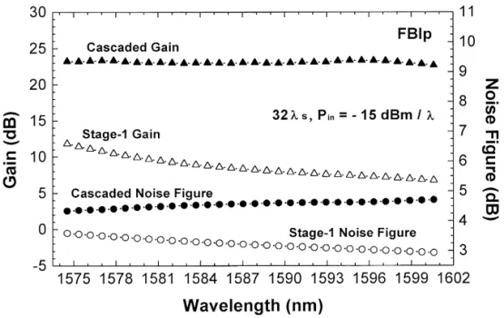
4. Characteristics of FBIp configuration
Based on the simulation results listed in Table 4, the FBIp pumping scheme is the best L-band EDFA choice for offering the highest channel output power with good channel gain uniformity and low noise figure characteristics for multi-wavelength L-band WDM lightwave systems. Fig. 5 shows the gain and noise figure characteristics at the end of stage-1 and the output port of FBIp-type EDFA, respectively.
Ž . Ž .
Fig. 3. The characteristics of a channel output power and b channel noise figure of four amplifier configurations without using the midway optical isolator.
The corresponding noise figure characteristic is 3.6
; 2.9 dB for the stage-1 EDFA and 4.3 ; 4.7 dB for
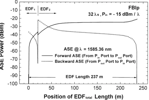
the cascaded EDFA, respectively. The corresponding channel ASE power evolution at l s 1585.36 nm in the EDF total length within the FBIp configuration is
showed in Fig. 6. The EDF total length is 237 m and
Ž
the midway isolator is put at the 20 m the length of
.
stage-1 EDF . Note that the ASE power at the 20-m
Ž
position has a 3.3-dB drop from y36.7 dBm to
.
Ž . Ž .
Fig. 4. The characteristics of a channel output power and b channel noise figure of five amplifier configurations with a midway optical isolator.
Žfrom y21.6 dBm to y74.9 dBm for the dash line..
The results confirm that the insertion loss of inter-staged components including the midway optical iso-lator is 3.3 dB and the optical isolation of midway optical isolator is about 50 dB.
Fig. 7 shows the maximum gain, the differential channel gain DG, and the maximum noise figure characteristics of the FBIp scheme as a function of
the ratio of EDF to the total EDF length. When the1
Ž .
Table 4
The inter-stage isolation and the output characteristics of all configurations by optimum EDF total length used in this work a
Characteristics L-band EDFA configurations
With midway optical isolator Without midway optical isolator
FFI FBIb FBIp BFI BBI FF FB BF BB
Ž .
Insertion loss of inter-stage dB 2.1 2.1 3.3 2.1 2.1 1.5 1.4 1.5 1.5
Ž .
EDF length m1 169 164 20 65 62 167 Single-staged 49 59
Ž .
Optimal EDF total length m 215 215 237 217 218 211 213 204 214
Ž .
EDF rEDF1 total % 78.6 76.3 8.4 30.0 28.4 79.1 Single-staged 24 27.6
Ž . Gma x dB 21.71 21.76 22.83 21.89 22.04 21.87 22.27 20.94 22.09 Ž . Gmi n dB 21.04 21.07 22.17 21.24 21.37 21.21 21.57 20.36 21.48 Ž . DG dB 0.67 0.69 0.66 0.65 0.67 0.66 0.70 0.58 0.61 Ž . NFma x dB 4.4 4.5 4.7 5.5 5.5 4.4 4.7 5.5 5.5 Ž . NFmi n dB 3.9 4.0 4.3 4.4 4.5 3.9 4.4 4.4 4.4 Ž . D NF dB 0.5 0.5 0.4 1.1 1.0 0.5 0.3 1.1 1.1 a
Lauched with 32 channel signals, each with an input power level of y15 dBm.
figure achieves F 5.5 dB. On the other hand, the
Ž .
ratio region is within 1.2% F EDF rEDF1 total % F
16.9%, the differential channel gain DG of F 0.7 dB is obtained. So, the ratio of 4.6% ; 16.9% of EDF rEDF1 total, is the allowable fiber ratio region to meet design criteria of DG F 0.7 dB and NF F 5 dB. Fig. 8 shows the effect of input signal power of each channel on the characteristics of maximum gain, the
differential channel gain DG, and the maximum noise figure of the FBIp configuration. For this FBIp scheme, to maintain the output differential channel gain of DG F 1 dB and the maximum noise figure of
F5.5 dB for 32 input channels, the allowable input
power range is from y15 to y14 dBm. When the channel input power range is from y18 to y11 dBm, the differential channel gain DG of F 3 dB
Fig. 5. The evolution of spectral channel gain and noise figure characteristics of the first-staged and the cascaded-staged amplifier for FBIp-type configurations.
Fig. 6. The forward and backward ASE channel power evolution at l s 1585.36 nm for the FBIp configuration versus the position of EDF length.
and the maximum noise figure of F 5.5 dB can be obtained for 32 input channels.
The optical isolation effect of the midway optical isolator on the channel gain and noise figure
charac-teristics of the FBIp configuration is shown in Fig. 9. We find that the channel output power characteristics are independent on the midway isolator when the isolation is greater than and equal to 18 dB. Fig. 10
Ž .
Fig. 7. The effect of EDF rEDF1 total % on the differential channel gain DG, maximum gain Gmax and maximum noise figure NFmax characteristics of the FBIp-type EDFA.
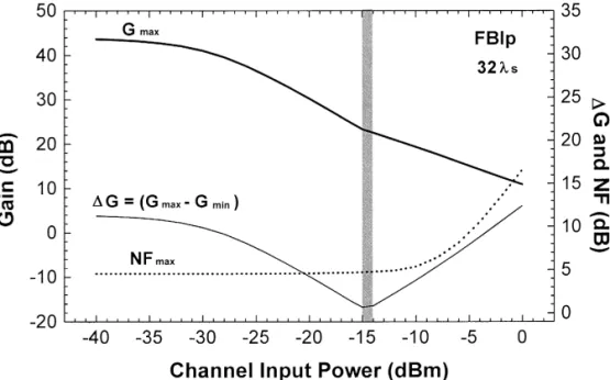
Fig. 8. The effect of input signal power of each channel on the differential channel gain DG, maximum gain Gma x, and maximum noise figure NFma xcharacteristics of the FBIp-type EDFA.
shows the maximum gain, the differential channel gain DG, and the maximum noise figure versus the pump power of each laser diode. The maximum
channel gain is gradually increasing and the maxi-mum noise figure is gradually decreasing when the pump power of each laser diode is increasing, each
Fig. 9. The effect of optical isolation of midway optical isolator on the differential channel gain DG, maximum gain Gma x, and maximum noise figure NFma xcharacteristics of the FBIp-type EDFA.
Fig. 10. The effect of pump power degradation of each pump laser diode on the differential channel gain DG, maximum gain Gma x, and maximum noise figure NFma x characteristics of the FBIp-type EDFA.
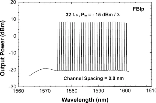
with an input power of y15 dBm per channel. The allowable pump power range of each laser diode is from 119 to 142 mW. That is, it allows a power degradation range of 23 mW of each pump LDs. Fig. 11 illustrates the output spectrum of the FBIp-type
EDFA with 32 input signal channels with a channel spacing of 0.8 nm.
In this work we also used a 980-nm pump laser diode to replace with the first pump laser in this FBlp L-band amplifier to investigate the
istics of such 980-nm forward pumped and 1480-nm
Ž .
backward pumped 980-nm q 1480-nm FBlp
scheme. We found that the gain spectrum profile of the 980-nm q 1480-nm pumped FBlp scheme with a 32-channel WDM signals are almost the same as that of the 1480-nm q 1480-nm pumped FBlp scheme, but with a lower channel output power with reduc-tion of about 1 dB, and therefore a reducreduc-tion of total amplifier output power of about 25 mW, and im-proved noise figure characteristics of about 0.3 to 0.1 dB. In consequence, from the high channel output with low gain variation of - 0.7 dB and low noise figure of - 5 dB point of view, the 1480-nm q 1480-nm pumped FBlp scheme is better than the 980-nm q 1480-nm pumped FBlp scheme.
5. Conclusions
We have theoretically investigated various config-urations of 1480-nm pumped L-band EDFA to
si-Ž .
multaneously achieve high gain G 20 dB with low differential channel gain of DG F 0.7 dB and low noise figure of F 5.5 dB. A total of nine L-band EDFA configurations using conventional EDF, oper-ated at 32 digital channels with y15 dBm input power per channel, have been examined and com-pared. Among these configurations, it is found that the pump-passed case in forward-and- backward pumping scheme, FBIp, is the best amplifier config-uration to offer the highest output power and gain
ŽG s22.83 dB, G s22.17 dB with moderate.
max min
Ž .
low noise figure NF s4.7 dB . The isolation of
max
midway isolator of G 18 dB is satisfied for the FBIp-type configuration. Another advantage is that this scheme allows a large fiber length ratio range of
4.6% ; 16.9% of EDF rEDF1 total, which relaxes the
construction of L-band EDFA. In addition, the pump power degradation of up to 23 mW is allowed for this configuration to maintain the characteristics of
DG F 0.7 dB and NF F 4.8 dB, but at the expense of
about 0.6 dB degradation of channel gain. Among these configurations, the single-staged forward-and-backward pumping scheme, FB, without using any inter-staged component can offer the second high
Ž
output power and gain G s22.27 dB, G s
max min
. Ž
21.57 dB with moderate low noise figure NFmaxs
.
4.7 dB . The investigation result provides the L-band EDFA configuration selection for multi-wavelength WDM lightwave systems.
Acknowledgements
This work was supported by the Opto-Electronics and Systems Lab., Industrial Technology Research Institute, Chutung, Hsinchu 310, of Taiwan.
References
w x1 D. Marcuse, A.R. Chraplyvy, R.W. Tkach, IEEErOSA J.
Ž .
Lightware Technol. 12 1994 885.
w x2 N. Shibata, R.P. Braun, R.G. Waarts, IEEE J. Quantum
Ž .
Electron. QE-23 1987 1205.
w x3 E. Desurvire, Erbium-Doped Fiber Amplifiers: Principles and
Applications, John Wiley and Sons, New York, 1994.
w x4 A. Bjarklev, Optical Fiber Amplifiers: Design and System
Applications, Artech House, Boston and London, 1994.
w x5 J.F. Massicott, J.R. Armitage, R. Wyatt, B.J. Ainslie, S.P.
Ž .
Craigryan, Electron. Lett. 26 1990 1645.
w x6 J.F. Massicott, R. Wyatt, B.J. Ainslie, Electron. Lett. 28 Ž1992 1924..
w x7 H. Ono, M. Yamada, Y. Ohishi, IEEE Photon. Technol. Lett.
Ž .
9 1997 596.
w x8 H. Ono, M. Yamada, T. Kanamori, S. Sudo, Y. Ohishi,
Ž .
Electron. Lett. 33 1997 710.
w x9 H. Ono, M. Yamada, S. Sudo, Y. Ohishi, Electron. Lett. 33 Ž1997 876..
w10 H. Ono, M. Yamada, T. Kanamori, Y. Ohishi, Electron. Lett.x
Ž .
33 1997 1477.
w11 H. Ono, M. Yamada, M. Shimizu, Y. Ohishi, Electron. Lett.x
Ž .
34 1998 1509.
w12 H. Ono, M. Yamada, T. Kanamori, S. Sudo, Y. Ohishi, J.x
Ž .
Lightwave Technol. 17 1999 490.
w13 K.I. Suzuki, H. Masuda, S. Kawai, K. Aida, K. Nakagawa,x
Ž .
Electron. Lett. 33 1997 1967.
w14 T. Sakamoto, J. Kani, M. Jinno, S. Aisawa, M. Fukui, M.x
Ž .
Yamada, K. Oguchi, Electron. Lett. 34 1998 392.
w15 H.S. Chung, M.S. Lee, D. Lee, N. Park, D.J. DiGiovanni,x
Ž .
Electron. Lett. 35 1999 1099.
w16 M. Jinno, T. Sakamoto, J. Kani, S. Aisawa, K. Oda, M.x
Ž .
Fukui, H. Ono, K. Oguchi, Electron. Lett. 33 1997 882.
w17 H. Ono, M. Yamada, M. Shimizu, Y. Ohishi, Electron. Lett.x
Ž .
34 1998 1513.
w18 T. Sakamoto, K. Hattori, J. Kani, M. Fukutoku, M. Fukui,x
Ž .
M. Jinno, K. Oguchi, Electron. Lett. 34 1998 1959.
w19 C.R. Giles, E. Desurvire, J. Lightwave Technol. 9 1991x Ž .