Mechanical and optical properties of ITO films with
anti-reflective and anti-wear coatings
Wen-Fa Wu, Bi-Shiou Chiou
)Department of Electronics Engineering and Institute of Electronics, National Chiao Tung UniÕersity, Hsinchu, Taiwan, ROC Received 7 August 1996; accepted 19 October 1996
Abstract
Ž .
In this study, radio frequency rf magnetron sputtered ITO films were coated with reactively sputtered SiO films. The2 microhardness, pull-off strength, scratch adhesion strength, optical transmittance and reflectance of the SiO rITOrsubstrate2
system are investigated. Coating of SiO enhances both the hardness and pull-off strength and reduces the scratch critical2 load of the system. The optical transmittance in the visible range is also improved with the addition of SiO .2
1. Introduction
Ž .
Transparent, conductive indium tin oxide ITO films exhibit a high electrical conductivity combined with high transmission in the visible spectral range. Hence, ITO has many applications, such as in trans-parent electrodes, anti-reflection coatings, display
w x
devices, and photoelectronic devices 1–3 . How-ever, although the visible transmittance of ITO films is high and the inherent absorption can be very low, a substantial refractive index mismatch exists
be-Ž . w x Ž .
tween the ITO film n f 2.0 4–10 and air n s 1 .
This results in significant reflection, particularly in the visible range, and consequently reduces visible transmittance. High visible reflectance may be an impediment to its utilization in some situations. It is therefore clear that a suitable antireflective coating, bringing down the front surface reflectance, can give
)
Corresponding author. Tel.: 715507; fax: q886-35-724361.
a substantial enhancement of the transmittance. Be-sides, abrasion of the film occurs during handling and usage, and results in degradation of film proper-ties. Hence, a coating which is both antireflective
ŽAR and anti-wear is preferable in the application of.
ITO films.
For a double layer AR coating with ITO as the high refractive index layer deposited on the
low-in-dex substrate, the refractive inlow-in-dex nA of the AR
layer on the ITO film must satisfy the following
w x condition 11 n2 n2 A ITO ns- F
Ž .
1 nair nswhere n is refractive index and the subscripts s and A stand for the substrate and the AR film, respec-tively. The substrates employed in this study are
Ž . Ž . w x
polycarbonate PC n s 1.586 11 and corning
Ž . Ž .
glass 7059 n s 1.523 . On the basis of Eq. 1 , the refractive index of the AR layer should be between 1.259 and 1.588 for PC substrates and between 1.234 and 1.621 for glass substrates. Coating of the
sput-0169-4332r97r$17.00 Copyright q 1997 Elsevier Science B.V. All rights reserved.
Ž .
tered ITO film with an evaporated MgF layer has2 been shown to significantly increase luminous and solar transmittance and reduce luminous reflectance
w12 . MgF has ideal optical and physical propertiesx
2
for such an application. However, MgF films can-2
not be fabricated with the sputtering process and rf
sputtered MgF films show a strong optical absorp-2
tion due to fluorine loss and magnesium oxidation
w11 . Reactively sputtered SiOx film, with a
refrac-2
w x
tive index of ; 1.4 13 , is a potential candidate for
the anti-wear, anti-reflection coating of sputtered ITO films.
In the present study, the mechanical properties, including microhardness, pull-off adhesion, and scratch adhesion of SiO coated ITO films are inves-2 tigated and the optical behavior is evaluated. PC is employed as one of the substrate materials. Because ITO films fabricated on plastics at low substrate temperature without any postdeposition annealing find many applications, such as plastic liquid crystal display devices, flexible electro-optical devices, and unbreakable heat-reflecting mirror. Previous studies
Ž .
suggest that low power radio frequency rf mag-netron sputtering of ITO on plastics provides highly
w x
conductive transparent ITO films 6,14,15 . It is be-lieved that the results obtained in this work will be helpful to those seeking to widen the production of sputtered optical film systems.
2. Experimental details
ITO and silicon dioxide films were prepared by using a commercial rf magnetron sputtering system
ŽIon Tech, UK . The sputtering targets were 1 inch. Ž
hot-pressed oxide ceramic 90 wt% In O2 3 and 10
Fig. 1. Cross-sectional SEM micrographs for ITO films with SiO2
˚ ˚
Ž .
coatings. Film thickness a ITO: ;1000 A, SiO : ;6000 A,2
˚ ˚
Ž .
and b ITO:;1000 A, SiO : ;30000 A.2
. Ž
wt% SnO , 99.99% purity and Si ceramic 99.999%2
.
purity supplied by Cerac, Inc., USA. The substrates employed were Corning 7059 glass and polycarbon-ate sheets. Substrpolycarbon-ates were placed on a holder above the target with a target-to-holder distance of 50 mm
and the holder was rotated at ; 10 roundsrmin by a
motor to provide good uniformity and prevent poly-carbonate from overheating. However, the film depo-sition rate is reduced because the substrate was rotated off the plasma region periodically. The vac-uum chamber was pumped by a diffusion pump.
Ž . Ž .
High purity Ar 99.999% and O2 99.5% was
Table 1
Mechanical properties of SiO rITOrsubstrate system2 b
Ž . Ž . Ž .
Substrate employed Microhardness HK Pull-off strength MPa Scratch critical load N
PC PC glass glass a ˚ ; 1000 A ITO 16.5" 0.7 4.97 17.86 11.7" 1.2 ˚ ˚ ; 1300 A SiO q ; 1000 A ITO2 18.5" 1.0 — 79.17 9.4" 0.9 a ˚ ˚ ; 6000 A SiO q ; 1000 A ITO2 84.2" 15.0 6.55 27.86 7.8" 0.8 a ˚ ˚ ; 30 000 A SiO q ; 1000 A ITO2 584.7" 47.7 10.98 21.39 6.6" 1.6 a
Failure occurred within glass substrates.
b
w x
introduced through a mass flow controller after the
vacuum chamber was evacuated to about 2.66= 10y4
Ž y6 .
Pa 2= 10 Torr . Details on the sputtering of ITO
w
and SiO2 films were described elsewhere 4–9,13–
x
16 .
The film thickness was measured with a stylus surface profiler. An ellipsometer was used to mea-sure refractive indices for films deposited on Si wafers. The microstructure of the film was analyzed
Ž
using a scanning electron microscope SEM, Hitachi
.
S-4000, Japan . The optical transmittance of the film was measured with an ultra violet–visible–near
in-Ž .
frared spectrophotometer Hitachi U-3410, Japan . The adhesion strength of the coating was measured by an adhesion pull tester and a scratching adhesion tester. In the scratching test a stylus is drawn over the sample surface under a continuously increasing normal force until the coating is detached. The nor-mal force on the indenter causing coating ment is called the critical load. The coating detach-ment was observed using acoustic emission detectors to measure high frequency vibrations caused by coat-ing detachment. Critical loads indicated were ob-tained by averaging the values of three to five differ-ent scratches. Detailed morphologies of scratch chan-nels were viewed with an optical microscope. The hardness was measured by Knoop hardness testing
Ž
technique MHT-4 ultra-microhardness tester,
Aus-.
tria . The load applied in the hardness measurement was 1 gf. Details on the hardness measurement were
w x
described elsewhere 14 .
3. Results and discussion
Fig. 1 gives the cross-sectional SEM micrographs
for ITO films with SiO coatings. A smooth struc-2
ture is observed in the SiO film, while a columnar2 structure is obtained in the ITO film.
A hard coating on a soft substrate reduces the wear by preventing ploughing on both the macro and micro scale. Hard coatings are thus particularly
use-ful in abrasive environments. Since SiO2 is harder
than ITO is, SiO2 may serve as a wear-resistant
Fig. 2. Acoustic emission curves for ITO films with SiO coatings2
coating to prolong the lifetime of ITO films during application. Table 1 summarizes the mechanical
properties of SiO rITOrPC substrate system. As2
indicated in Table 1, SiO2 coating enhances the
microhardness of the ITOrPC substrate consider-ably. The thicker the SiO film, the larger the micro-2
h ard n ess. T h e p u ll-o ff stren g th o f th e
SiO rITOrsubstrate system is also improved with2
the coating of SiO , especially for samples with2
glass substrate of which all failures occur within glass substrates. This indicates that the pull-off adhe-sion of SiO rITO to glass substrate is larger than the2 strength of the glass substrate.
The scratch test is also employed to study the
adhesion of the SiO -coated ITO film and the sub-2
strate. The critical load measured by a scratch tech-nique can be thought of as the adhesion strength of the film on the substrate when films are subjected to wearing andror abrasion. The scratch critical load shows a decreasing trend with increasing thickness of the SiO film. Strain energy stored in the coating2 may be one of the reasons which cause loss of scratch adhesion strength. The strain energy u stored
w x
in the film is given by 17
u s s2r2 E J my3 2
Ž
.
Ž .
The volume energy per unit area on the substrate is thus given by s2d s2d s s I I y2 ud s q
Ž
J m.
Ž .
3 2 Es 2 EIwhere s , E, and d represent the stress, Young’s modulus, and thickness of the film, respectively. The
subscripts s and I stand for SiO2 and ITO,
respec-tively. When the SiO2 film is thicker, the volume
energy ud exceeds a critical value at smaller scratch load, exfoliation of the film from the substrate will occur and cracks generated. However, the detailed mechanism which causes the loss of scratch adhesion is subjected to further investigation.
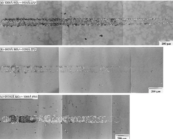
Figs. 2 and 3 illustrate corresponding acoustic emission curves and optical micrographs of scratch
channels for SiO -coated ITOrglass substrate, re-2
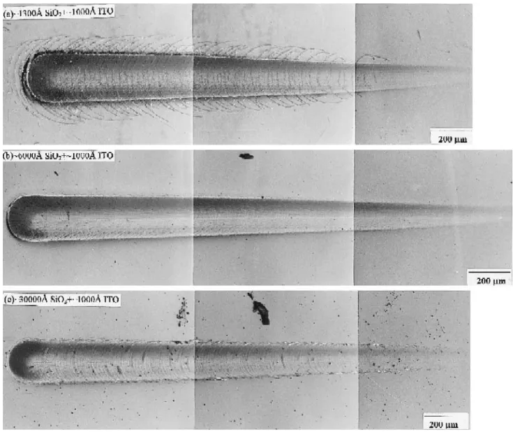
spectively. Here the load pressed on the indenter tip is continuously increased at the loading rate of 100 Nrmin. The indenter is drawn across the surface of the sample with a scanning speed of 10 mmrmin. The load is 25 N at the end of the scratch channel. Fig. 4 shows optical micrographs of scratch
chan-nels for SiO2 coated ITO on PC substrates. The
loading speed and scratching speed are 25 Nrmin and 10 mmrmin, respectively. The load is 5 N at the end of the scratch channel. For the specimens coated
˚
˚
with ; 1000 A ITO and ; 1300 A SiO , the cracks2
perpendicular to the scratch channel are observed and cracks are more intense at higher loads. These cracks coincide with the well-known ring cracks due
w x
to tensile stresses near the edge of contacts 18 . As
mentioned previously, SiO2 coating enhances the
microhardness of the ITOrPC substrate consider-ably. Only few cracks are observed along the scratch channel with increasing thickness of anti-wear SiO2
Ž .
coating, as shown in Fig. 4 b . However, higher internal stress will exist in the films for thicker films, the semicircular cracks within the scratch channel
are observed as the thickness of SiO2 coating
in-creases to ; 3 mm. These cracks form as the
inden-ter deforms the coating and the underlying substrate, resulting in tensile bending moments within the coat-ing as it is pushed down underneath the indenter
w18 .x
Fig. 5 shows the transmittance of a single layer
ITO film and ITO film with SiO2 coating. The
˚
nominal thicknesses of ITO and SiO2 are 1009 A
˚
and 807 A, respectively. An increase in visible
trans-mittance is observed for ITO with SiO film. Coat-2
ing of SiO on ITO does reduce the visible reflection2 and enhance the transmittance as expected. However, the measured reflectance spectrum deviates from the theoretically calculated one, as exhibited in Fig. 6.
In the design of double-layer AR coatings, two approaches can be employed. One is to select avail-able coating materials with prefixed values of the indices, and calculate the thickness required to give
Fig. 5. Transmittance of a single-layer ITO film and ITO film
˚
with SiO coating. Nominal film thickness: ITO: 1009 A, SiO :2 2
˚
807 A.
Fig. 6. The calculated and measured reflectance spectra for ITO
˚
films with SiO coatings. Nominal film thickness: ITO: 1009 A,2
˚
SiO : 807 A.2
w x
zero reflectance 19 . The other approach is to use layers with optical thickness that are integral multi-ple of lr4 and compute the refractive indices re-quired to give zero reflectance. However, the practi-cal refractive index is not a parameter which can be varied at will. In addition, materials suitable for thin film applications are limited in number and the designer has to use whatever is available. Hence, the first approach is adopted, the refractive indices for
ITO and SiO2 were specified and the thickness to
achieve zero reflectance calculated.
The difference between experimental data and theoretical derivations is attributed to uncertainties in film thickness and refractive index. In this study, a constant film deposition rate was assumed and film thickness was obtained by controlling the deposition
w x
time 7,14 . Errors in the time and deposition rate measurement would lead to deviation between real and nominal film thickness. In addition, a lossless
Ž .
film i.e., extinction coefficient k s 0 with a con-stant refractive index n is assumed in the calcula-tion. However, previous investigations indicate that the optical constants n and k of the film would vary with wavelength and other parameters such as film
w x
thickness 4,8 . However, SiO coating on ITO does2
improve the mechanical hardness, pull-off strength, and the visible transmittance of ITO film. Neverthe-less, stringent control on film thickness is needed to further improve the antireflection performance.
4. Conclusions
Ž .1 Coating of SiO on ITO film improves both2
the microhardness and pull-off strength of the film.
For the SiO rITOrPC substrate system, the micro-2
hardness increases from 16.5 HK to 585 HK as the
˚
thickness of SiO2 increases from 0 to ; 30000 A.
For samples with glass substrate, all failures occur within the glass after pull-off test.
Ž .2 T he scratch critical load of the
SiO rITOrglass substrate decreases with the in-2
crease of SiO thickness. Residual strain energy in2 the SiO coating is believed to be one of the reasons2 which cause loss of scratch adhesion strength.
Ž .3 An increase in the visible transmittance is
observed for ITO films with SiO2 coating. The
difference between the measured and calculated re-flectance spectrum results from errors in film thick-ness estimation and the assumption of lossless and dispersionless optical constants of the film.
Ž .4 SiO is a potential anti-reflective and anti-wear2 coating material for the transparent, conductive ITO.
Coating of ITO with SiO improves the mechanical2
and optical properties of the ITOrsubstrate system.
Acknowledgements
This work is supported by the Chung-Shan
Insti-Ž
tute of Science and Technology contract No. CS
.
83-0210-D-009-001 and partly supported by the
Na-Ž
tional Science Council of Taiwan, ROC contract
.
No. NSC 82-0417-E009-395 .
References
w x1 J.C. Manifacier, Thin Solid Films 90 1982 297.Ž .
w x2 K.L. Chopra, S. Major and D.K. Pandya, Thin Solid Films
Ž .
80 1981 143.
w x3 F.L. Bouquet and C.R. Maag, IEEE Trans. Nucl. Sci. NS-33 Ž1986 1408..
w x4 W.F. Wu and B.S. Chiou, Appl. Surf. Sci. 68 1993 497.Ž . w x5 B.S. Chiou, S.T. Hsieh and W.F. Wu, J. Am. Ceram. Soc. 77
Ž1994 1740..
w x6 W.F. Wu and B.S. Chiou, Thin Solid Films 247 1994 201.Ž . w x7 B.S. Chiou, S.T. Hsieh and W.F. Wu, Appl. Surf. Sci. 74
Ž1994 297..
w x8 W.F. Wu and B.S. Chiou, Semicond. Sci. Technol. 9 1994Ž .
1242.
w x9 W.F. Wu and B.S. Chiou, Semicond. Sci. Technol. 11 1996Ž .
196.
w10 A.J.P. Theuwissen and G.J. Declerck, Thin Solid Films 121x Ž1984 109..
w11 W.F. Wu, Ph.D. Thesis, National Chiao Tung University,x
Ž .
Hsinchu, Taiwan 1994 .
w12 I. Hamberg, A. Hjortsberg and C.G. Granqvist, Appl. Phys.x
Ž .
Lett. 40 1982 362.
w13 W.F. Wu and B.S. Chiou, Semicond. Sci. Technol. 11 1996x Ž .
1317.
w14 B.S. Chiou and S.T. Hsieh, Thin Solid Films 229 1993 146.x Ž . w15 W.F. Wu and B.S. Chiou, Thin Solid Films, in press.x w16 W.F. Wu and B.S. Chiou, Thin Solid Films, in press.x w17 A. Kinbara, S. Baba, N. Matuda and K. Takamisawa, Thinx
Ž .
Solid Films 84 1981 205.
w18 P.J. Burnett and D.S. Rickerby, Thin Solid Film 154 1987x Ž .
403.
w19 K.L. Chopra and I. Kaur, Thin Film Device Applicationsx ŽPlenum Press, New York and London, 1983 ..