Mechanistic study of cobalt catalyzed growth of carbon nano
fibers in a confined
space by plasma-assisted chemical vapor deposition
Chen-Chun Lin
a, Fu-Ming Pan
a,⁎
, Kai-Chun Chang
a, Chuan-Wen Kuo
a, Cheng-Tzu Kuo
ba
Department of Materials Science and Engineering, National Chiao Tung University, Hsinchu, Taiwan, ROC
bDepartment of Materials Science and Engineering, MinDao University, Changhua, Taiwan, ROC
a b s t r a c t
a r t i c l e i n f o
Article history: Received 19 August 2008
Received in revised form 6 May 2009 Accepted 20 June 2009
Available online 27 June 2009 Keywords:
Carbon nanofibers Anodic aluminum oxide
Carbon nanofibers (CNFs) were grown in the porous anodic aluminum oxide (AAO) thin film grown on the Si wafer by electron cyclotron resonance chemical vapor deposition using cobalt as the catalyst. A larger Co particle electrodeposited in the AAO pore channel produced vertically aligned CNFs with a tube diameter in compliance with the pore size of the AAO template. On the other hand, a smaller Co particle resulted in CNF growth with a nonuniform distribution of the tube diameter and a sparse tube density. Amorphous carbon residue produced under the plasma-assisted CNF growth condition seemed to play an essential role leading to the observation. A growth mechanism is proposed to delineate the volume effect of the electrodeposited Co catalyst on the CNF growth confined in pore channels of the AAO template.
© 2009 Elsevier B.V. All rights reserved.
1. Introduction
For many technical applications of carbon nanotubes (CNTs) and nanofibers (CNFs), such as interconnects for integrated circuits[1], CNT purification by zeolite supports[2]andfield emission emitters
[3,4], CNTs/CNFs are required to be selectively grown in a confined region. Unlike CNT/CNF growth in an open space, the geometric configuration of a confined space will restrain the transport behavior of the precursor gas species and the catalyst area directly exposed to the precursors, thereby resulting in a growth kinetics different from CNT/CNF growth on a blank substrate. This is more likely to occur to CNT/CNF growth by plasma-assisted chemical vapor deposition (PACVD). Because of the applied sample bias and reactive radicals as well as ionic species, etch and deposition of graphitic structure and carbonaceous residue under a typical PACVD condition can be greatly affected by the spacial geometry. Due to highly aligned pore channels and a nanosized pore diameter, anodic aluminum oxide (AAO) has been widely used as a template to regulate CNT/CNF growth by catalytic chemical vapor deposition (CVD)[5–9]. The high aspect ratio of AAO pore channels provides a distinct CNT/CNF growth environment from that on an open substrate. This is particularly true for CNT/CNF growth via the tip-growth mode. Because the close contact between the catalyst particle and the pore wall can disturb carbon diffusion over the catalyst surface, carbon transport via surface diffusion to the bottom of
the catalyst particle for facilitating growth of graphene sheets, as some models proposed, seems unlikely. Moreover, hydrogen radicals, which are believed to play an essential role affecting the resulting morphology and microstructure of CNTs/CNFs under an open growth condition, are prohibited from reaching the bottom of the catalyst particle in the confined pore channel, thus leading to the formation of CNTs/CNFs with a nanostructure different to some extent from that in an open space.
In this study, we grew CNTs/CNFs in the AAO template by electron cyclotron resonance chemical vapor deposition (ECR-CVD), and studied the particle size effect of the electrodeposited Co catalyst on CNT/CNF growth in the pore channel. CNFs can be grown under a synthesis condition similar to that for CNT growth, and, very often, can be produced simultaneously with CNTs during nanotube growth. Furthermore, CNFs usually have similar superficial morphological features like CNTs, they are thus often referred to as CNTs in the literature. In the study, many carbon nanostructures grown in AAO pore channels exhibited morphological and crystalline features more like carbon nanofibers as defined by Melechcko et al., we will hereafter use carbon nanofibers (CNFs) through the report[10].
2. Experimental
The preparation of the AAO template was started with sputter depositing an aluminum thinfilm 2 µm thick on the 4 in. Si wafer. In order to prepare highly aligned AAO pore channels, two-step electrochemical anodization was performed. The detail of the anodization procedure has been previously described [7,11]. After the second anodization step, an Al layer ~ 200 nm thick was deliberately remained beneath the AAO template, and used as the ⁎ Corresponding author. Department of Materials Science and Engineering, National
Chiao Tung University, 1001, Ta Hsueh Rd., Hsinchu, Taiwan 30050, ROC. Tel.: + 886 3 5131322; fax: + 886 3 5724727.
E-mail address:[email protected](F.-M. Pan).
0925-9635/$– see front matter © 2009 Elsevier B.V. All rights reserved. doi:10.1016/j.diamond.2009.06.002
Contents lists available atScienceDirect
Diamond & Related Materials
substrate for Co catalyst electrodeposition. Electrodeposition of Co was carried out in the electrolyte mixture of CoSO4 and H3BO3by
applying an AC voltage of 12.3 Vrms. The size of the Co particle in AAO
pore channels was tuned by varying the deposition time. To deposit CNFs in the AAO template, the Co catalyst wasfirst treated with the H2
plasma at 600 °C for 10 min in the ECR-CVD system. CNF growth was then carried out in a gas mixture of CH4and H2(5 sccm/25 sccm) at
600 °C for 35 min under the following growth conditions: power 750 W, substrate bias−100 V, working pressure ~2×10− 3Torr. CNFs
on the AAO template were characterized by scanning electron microscopy (SEM, JEOL JSM-6500F), transmission electron microscopy (TEM, Philips TECNAI 20), Raman spectroscopy (Jobin Yvon LabRam HR), and focus ion beam (FIB, FEI Nova 200).
3. Results and discussion
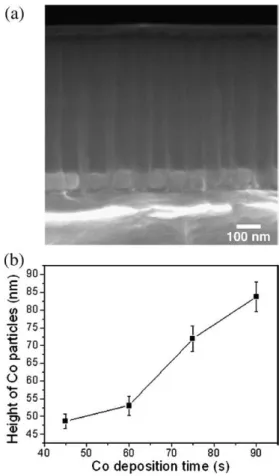
Fig. 1shows the SEM image of Co particles electrodeposited in the AAO template for 75 s. Co particles were uniformly electrodeposited at the bottom of AAO pore channels. Because of the AAO pore channel confinement, the diameter of the deposited Co particle was in accordance with the AAO pore diameter, ~80 nm. The size and thus the height of the electrodeposited particle in AAO pores increased with the electrodeposition time.Fig. 1(b) shows the plot of the height of the Co particle as a function of the electrodeposition time.Fig. 2
shows the side-view SEM images of CNFs grown out of the AAO template with Co catalysts electrodeposited for various times. For samples with Co catalysts deposited for 45 and 60 s (Fig. 2(a) and (b)), CNFs had irregular shapes with a sparse tube density and a diameter smaller than the AAO pore size. On the other hand, as the catalyst deposition time increased to 75 and 90 s (Fig. 2(c) and (d)), vertically
aligned CNFs were grown out over the AAO surface with a tube diameter close to the AAO pore size. FromFig. 2(a) and (b), a residual deposit can be clearly seen to cover a large area of the AAO surface. Amorphous carbon (α-C) residue is usually an inevitable byproduct during CNF growth by plasma-assisted CVD process[7,12,13]. Raman spectra (not shown) showed a low intensity ratio of the G band to D band (IG/IDb0.36) for samples with the Co catalyst deposited for
b60 s, indicating that a significant amount of α-C was deposited on the AAO template during the CNF growth. The occurrence of theα-C deposit appeared to be closely related to the distribution of CNFs grown out of the AAO pores. Theα-C was heavily deposited around CNFs, but became scarce away from the CNFs. This suggests that the CNF growth was accompanied by the concurrentα-C deposition in the AAO pore channel.
Fig. 3shows the cross-sectional SEM images of CNFs grown in the AAO template. CNFs grown with a smaller Co particle size were seriously distorted in shape and some were capped in the AAO pore channels (marked by circles) by theα-C deposit as shown inFig. 3(a) for the Co catalyst deposited for 60 s. Most CNFs had a diameter smaller than the AAO pore size and those CNFs extending out of the AAO pores had a gradual decrease in the tube diameter along the tube shaft. It can be clearly seen that the lower part of CNFs inside the pore channels was embedded by lumps of precipitate (marked by arrows). For those pore channels from which CNFs were completely detached during SEM specimen preparation, the pore wall surface exhibited a scaly and wrinkled feature, suggesting that CNF growth was accompanied by precipitation of, probably,α-C. On the other hand, according toFig. 3(b), CNFs grown with the Co catalyst deposited for 90 s had the growth direction much more compliant with the pore channel, and were vertically aligned after extending out of the pore.
Fig. 3(c) shows the SEM image of the AAO template treated with the same CNF deposition condition but without the Co catalyst. The top portion of the AAO exhibited a clean but jagged feature, suggesting that the AAO template surface was subject to plasma etch during the PACVD process. It have been reported that CNTs/CNFs could be grown in the AAO template without metallic catalysts[14,15]. However, no CNF growth was observed in the study, and the pore wall surface was very smooth. The observation implied that the Co particle played a major role not only catalyzing the CNF growth but also facilitating deposition of theα-C residue.
The TEM image of an FIB prepared sample with the Co catalyst deposited for 90 s is shown inFig. 4(a). The CNF growth time of the sample was deliberately controlled to keep the length of the CNFs smaller than the height of the AAO pore channels. It can be clearly seen that cone-shaped catalyst particles were present at the tip of the CNFs, indicating that the CNF growth in the AAO template was via the tip-growth mode. Because some Co particles remained at the pore bottom of the AAO template, the electrodeposited Co particle must be ripped apart during the CNF growth. Co particle fragments were also observed inside the CNF shaft.Fig. 4b shows the TEM image of several nanofibers grown with the Co catalyst deposited for 90 s. The CNFs were separated from the AAO template by ultrasonic agitation in ethanol. Some Co particles were stuck to the root of the CNFs. They were likely those originally left at the AAO pore bottom during the CNF growth but detached from the pore channels with the CNFs during TEM sample preparation. The inset is a high-resolution TEM (HRTEM) image for the area near the tip of a CNF grown with the Co catalyst deposited for 90 s. The CNF had ~61 well-ordered graphitic layers near the bottom of the cone-shaped catalyst particle, which had the interlayer distance of ~3.7 Å. For comparison, CNFs grown with Co deposited for 60 and 75 s had ~34 and ~53 graphitic layers, respectively.
The vapor–liquid–solid model is a commonly accepted CNT/CNF growth mechanism, which suggests that carbon diffusion in the liquefied metal catalyst is a required step for CNF growth. The cone-shaped catalyst and the segmentation of Co particles shown in the TEM images are an implication of Co liquefaction during the CNF Fig. 1. (a) SEM image of the AAO template with the Co catalyst electrodeposited for 75 s;
(b) (solid curve) the plot of the Co particle size (height) as a function of the Co electrodeposition time.
growth in the AAO template. It has been proposed that a temperature gradient can be developed in the catalyst particle as the concentration distribution of the dissolved carbon is nonuniform in the particle[16]. The catalyst has a higher temperature in the region supersaturated with carbon, and graphene sheets develop from the region with a smaller carbon concentration[17]. We thus propose that the particle segmentation probably resulted from the temperature gradient developing in the Co particle. The top portion of the Co particle was liquefied earlier than the bottom portion due to the quicker supersaturation with carbon, which was supplied by the inflowing carbonaceous plasma species under the CNF growth condition. As the liquefied Co particle moved upward with the growing CNF shaft, the Co particle was eventually separated leaving the unliquefied part at the bottom of the AAO pore channel. Besides, because Co has a reasonable wetting strength with aluminum oxide[18,19], it was likely that the capillary force might assist in lifting the liquefied Co particle and thus allow easy precipitation of graphitic sheets at the bottom of the liquefied particle.
As discussed above, CNF growth on the AAO template was accompanied by deposition ofα-C, and more α-C was deposited for a smaller Co particle. Theα-C accumulation on the pore wall surface could hinder the motion of the liquefied catalyst particle in the pore channel, thereby changing the moving direction and geometric shape of the catalyst during the CNF growth. This can explain why most CNFs grown under a condition of heavyα-C deposition showed a twisted feature inside the pore channels and had afiber diameter smaller than the AAO pore size. In addition, fromFig. 4b, many nanosized particles, probably Co, adhered to the tube surface of the CNFs. It is possible that the rough wall surface of the AAO pore channel, resulting from theα-C deposition, disturbed the movement of the liquefied Co particle on the tip of the growing CNF, and thereby stripped off surface atoms from
the Co catalyst particle, which might later agglomerate and adhere to the growing CNFs.
The growth mechanism of CNFs in AAO pore channels is schematically illustrated inFig. 5. The AAO pore channels not only limit the flow direction and theflux of plasma species toward the Co catalyst but also define the exposed area of the Co particle, which is roughly the pore size of the AAO template. Because the height of the open pore channel is much larger than that of all the Co particles under study, it seems unlikely that the Co particle size can significantly affect the diffusion behavior of gaseous species in the pore channel at the beginning of the CNT growth. Therefore, the impinging rate of carbonaceous and hydrogen radicals and ions onto the catalyst surface should be independent of the height of the Co particle. Once adsorbed and decomposed on the Co catalyst surface, carbon species may diffuse on the surface and dissolve into the particle. The Co particle becomes supersaturated with carbon on the top region earlier than the lower part, resulting in the development of a temperature gradient in the particle and thus Co liquefaction occurs earlier in the top region. Carbon atoms precipitating at the bottom of the liquefied Co segment then grow into graphitic sheets, forming carbon nanofibers in the AAO pore channel via the tip-growth mode. Because etching theα-C deposit by plasma species is not effective in the pore channel due to the high aspect ratio, removal of carbonaceous deposit in the pore channel is more sluggish than on the AAO template surface. Carbon dissolution into the Co particle becomes the major pathway for reducing surface concentration of the carbon deposit. Because carbon becomes saturated more quickly in the smaller particle than the bigger one, moreα-C may remain on the particle surface. If theα-C deposition prevails over CNF growth, extensiveα-C accumulation can occur on the top of the catalyst and the pore wall, thus retarding the CNF growth. Theα-C deposit can modify the geometric shape of the liquefied catalyst and thus diminish active catalytic area, thereby leading to growth of CNFs with a smaller Fig. 2. SEM images of CNFs grown for 35 min on the AAO template with different Co catalyst sizes: (a) 45 s; (b) 60 s; (c) 75 s; and (d) 90 s.
diameter and a distorted shape. In the extreme situation, the pore opening may be completely blocked by theα-C deposit before the CNF grows out of the pore, thus terminating the inflow of the precursor species and stopping the CNF growth. On the other hand, the bigger Co
particle dissolves more carbon atoms and, therefore, accumulation ofα-C on the surface can be effectively diminished, making CNF growth in the pore channel more favorable. Once CNFs grow out of the AAO pore surface, plasma etch becomes effective to remove excessive carbon Fig. 3. (a) Side-view SEM image of CNFs grown for 35 min in the AAO template with Co catalyst deposited for 60 s. CNFs capped by the surfaceα-C layer are marked by circles, and α-C deposits embedding CNFs are marked by arrows; (b) and (c) are cross-sectional SEM images for CNF grown for 35 min on the AAO template with Co catalyst deposited for 90 s and without the Co catalyst, respectively.
Fig. 4. TEM images of CNFs grown with the Co catalyst deposited for 90 s: (a) an FIB prepared sample of which CNFs were inside the AAO pore channels; (b) CNFs separated from AAO pore channels by ultrasonic agitation. The inset is the high-resolution TEM image of the area near the tip of a CNF.
deposit on the Co catalyst and plasma precursors can reach the catalyst surface without much obstacle. Thus CNFs can be grown continuously under a growth condition similar to that in an open space.
4. Summary
CNFs were grown in the AAO template by ECR-CVD using electrodeposited cobalt as the catalyst. The tube density, diameter
and tube alignment of CNFs grown in AAO pore channels strongly depended on the size of the electrodeposited Co particle. Carbon dissolution in the Co particle at the bottom of the pore channel induced a temperature gradient and Co melting in the particle, leading to the segmentation of the Co particle in the AAO pore channel. When the Co catalyst particle was small, heavy deposition ofα-C took place in the pore channel under the plasma-assisted CVD condition, and the CNF growth was adversely affected. A growth mechanism was proposed to delineate the effect of the Co catalyst size on the CNF growth in the AAO pore channels.
Acknowledgements
This work was supported by the National Science Council of ROC under Contract No. NSC95-2121-E009-312 and Chunghwa Picture Tubes, Ltd., Taiwan. Technical support from the National Nano Device Laboratories is gratefully acknowledged.
References
[1] F. Kreupl, A.P. Graham, G.S. Duesbger, W. Steinhögl, M. Liebau, E. Unger, W. Hönlein, Microelectronic Eng. 64 (2002) 399.
[2] K. Hernadi, A. Fonseca, J.B. Nagy, D. Bernaerts, A. Fudala, A.A. Lucas, Zeolites 17 (1996) 416.
[3] C.C. Lin, K.C. Chang, F.M. Pan, C.T. Kuo, M. Liu, C.N. Mo, Diam. Relat. Mater.16 (2007) 1388. [4] N.V. Quy, N.D. Hoa, M. An, Y. Cho, D. Kim, Nanotechnology 18 (2007) 345201. [5] J. Li, C. Papadopoulos, J.M. Xu, M. Moskovits, Appl. Phys. Lett. 75 (1999) 367. [6] J.S. Suh, J.S. Lee, Appl. Phys. Lett. 75 (1999) 2047.
[7] P.L. Chen, J.K. Chang, C.T. Kuo, F.M. Pan, Appl. Phys. Lett. 86 (2005) 123111. [8] H.Y. Yap, B. Ramaker, A.V. Sumant, R.W. Carpick, Diamond Relat. Mater. 15 (2006)
1622.
[9] S.H. Jeong, O.J. Lee, K.H. Lee, S.H. Oh, C.G. Park, Chem. Mater. 14 (2002) 4003. [10] A.V. Melechko, V.I. Merkulov, T.E. Mcknight, M.A. Guillorn, K.L. Klein, D.H.
Lowndes, M.L. Simpson, J. Appl. Phys. 97 (2005) 041301.
[11] P.L. Chen, C.T. Kuo, T.G. Tsai, B.W. Wu, C.C. Hsu, F.M. Pan, Appl. Phys. Lett. 82 (2003) 2796. [12] K.B.K. Teo, M. Chhowalla, G.A.J. Amaratunga, W.I. Milne, D.G. Hasko, G. Pirio, P.
Legagneux, F. Wyczisk, D. Pribat, Appl. Phys. Lett. 79 (2001) 1534.
[13] S. Hofmann, M. Cantoro, B. Kleinsorge, C. Casiraghi, A. Parvez, J. Robertson, C. Ducati, J. Appl. Phys. 98 (2005) 034308.
[14] J.S. Lee, G.H. Gu, H. Kim, K.S. Jeong, J. Mae, J.S. Suh, Chem. Mater. 13 (2001) 2387. [15] B.D. Yao, N. Wang, J. Phys. Chem. B 105 (2001) 11395.
[16] H. Kanzow, A. Schmalz, A. Ding, Chem. Phys. Lett. 295 (1998) 525. [17] A.R. Harutyunyana, T. Tokune, E. Mora, Appl. Phys. Lett. 86 (2005) 153113. [18] X.G. Wang, J.R. Smith, Phys. Rev. B 70 (2004) 081401.
[19] S.A. Chambers, T. Droubay, D.R. Jennison, T.R. Mattsson, Science 297 (2002) 827. Fig. 5. Schematic illustration of CNF growth mechanism in the AAO pore channel:
(a) CNF growth with a large Co catalyst; (b) CNF growth with a small Co catalyst. The dots stand for carbon dissolved in the Co particle, and the number and size of the dots denote the amount of carbon dissolved. Detailed description about the growth mechanism is given in the text.