IEEE TRANSACTIONS ON MAGNETICS, VOL. 43, NO. 6, JUNE 2007 2579
Optimal Design of Magnetic Zooming Mechanism Used in
Cameras of Mobile Phones via Genetic Algorithm
Paul C.-P. Chao
1and Sung-Ching Wu
2Department of Electrical and Control Engineering, National Chiao Tung University, Hsinchu, 300 Taiwan Department of Mechanical Engineering, Chung-Yuan Christian University, Chungli, 320 Taiwan
One of the important features for the cameras in cell phones today is the optical zooming. This paper presents design and optimiza-tion of a zooming mechanism via genetic algorithm (GA). The goal is to maximize voice coil motor (VCM) sensitivity in the zooming mechanism and, simultaneously, to keep various dimensions under physical limitation. The optimization first chooses key independent dimensions as design variables, and then establishes the computation procedure for the VCM sensitivity via equivalent circuitry. The correctness of the expression is validated by finite element analysis (FEA). Optimization results lead to that dimensions of the yokes and magnets reach optima at their extremes in preset constraints, and in result, high uniformity of the magnetic flux intensity along guide ways of the VCM is achieved.
Index Terms—Cell phones, genetic algorithm (GA), voice coil motor (VCM), zooming mechanism.
I. INTRODUCTION
T
HE latest trends of mobile phone development are toward multifunctionality, which includes an installed small-sized digital camera. With advances in technologies of charge coupled device (CCD) and/or complementary metal–oxide–semicon-ductor (CMOS) sensors, the resolutions of the aforementioned digital cameras can be improved above seven million pixels. However, the cameras in mobile phones still lack functions owned by conventional cameras due to space limitation, such as autofocusing and zooming, etc. As to the zooming function, there already exist some mobile phones on the market having the zooming capability, which is, nonetheless, realized by digital zooming. For digital zooming, certain amount of time is required for image processing; consequently, the camera could not respond in real time, and the resolutions of pictures are inevitably reduced. To remedy the problem, an optical zooming could be a promising alternative, since it responds in real time and then preserves original picture resolution.A common optical zooming system includes two subsys-tems: a lens module and actuator mechanism. Some past patents were devoted to proposing the lens module [1]–[3] and actuator mechanism [4], [5]. However, none of them are devoted to miniaturization of the mechanism to fit in the small space of a common mobile phone. To this end, a small-sized optical zooming mechanism is proposed in this paper, as shown in Fig. 1(a). It is essentially composed of a couple of lens, voice coil motors (VCMs), guide rods, yokes, and magnets. By adjusting relative distance between the two lenses, the proposed optical mechanism is able to conduct the function of zooming. While paying effort to reduce size of the optical zooming mechanism, the sensitivity of actuation by the mecha-nism ought to be maximized simultaneously in order to render shortest traveling time of the lens. Therefore, the optimization technique, genetic algorithm (GA) [6], is employed herein to maximize the VCM sensitivity and keep various dimensions to
Digital Object Identifier 10.1109/TMAG.2007.893317
Color versions of one or more of the figures in this paper are available online at http://ieeexplore.ieee.org.
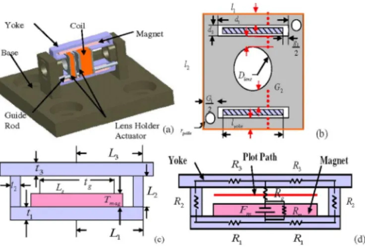
Fig. 1. (a) Structure of zooming mechanism. (b) Front-viewed geometry of lens holder. (c) Yoke-magnet system. (d) Equivalent circuitry.
their possible minimums. Results indicate that dimensions of the yokes and magnets reach optima at their extremes inside preset constraints, and high uniformity of the magnetic flux intensity along guide ways of the VCMs is also achieved.
II. MECHANISMDESIGN
The structure of the optical zooming mechanism is designed as shown in Fig. 1(a), which consists of two subsystems: a lens moving subsystem and a VCM subsystem. The lens moving subsystem includes two zooming lens holders and their guide rods, while the VCM subsystem has permanent magnets, coils, and yokes. The material of both lens holders is polyoxymethy-lene (POM) due to its light weight and ease to manufacture. Fig. 1(b) shows the geometry of the designed holders from front view. Coils are revolved around the holders to carry current for generating forces to move the lens. There are two yoke-magnet subsystems on which the lens holders ride. Two pieces of yokes made of low-carbon steel and in U and flat shapes are employed to surround a permanent magnet made of neodymium–iron–boron (Nd–Fe–B). In this way, magnetic flux can be formed perpendicular to coil length and then generating required electromagnetic force to move the lens holders.
2580 IEEE TRANSACTIONS ON MAGNETICS, VOL. 43, NO. 6, JUNE 2007
Fig. 2. (a) Equivalent circuitry. (b) Simplified circuitry.
III. ELECTROMAGNETICANALYSIS
The actuation forces on the lens holders are generated by the interaction between the current carried by the coils and the mag-netic flux running through them. The forces are called Lorentz forces and are in the form of
(1)
where and are VCM current and wire length, while is magnetic flux density in the air gap of the yoke-magnet system shown in Fig. 1(c). This density would be computed based on equivalent circuitry and finite elements in the following two sections, respectively. The theory of equivalent circuitry is used to establish relation between VCM’s applied voltage and flux density in air gap to perform later optimization of the whole mechanism, while the finite elements are employed to validate the results derived by equivalent circuitry. In both analyses, the relative permeability of steel yoke is 200, while the coercive force of the Nd–Fe–B magnet is 99 500 Oe.
A. Equivalent Circuitry
The establishment of equivalent circuitry to calculate the magnetic flux density is completed in steps. The first step is to construct an equivalent magnetic circuitry as shown in Fig. 1(d), transformed to an alternative electric circuitry in Fig. 2(a), and finally simplified as in Fig. 2(b). In these figures, , and are equivalent reluctances of the yokes in different portions, while and are those of air gap and magnet. is the magnetomotive force (MMF) of the magnet. The second step is to calculate reluctances by
(2)
where is the length of magnetic material experiencing flux, is permeability, and is cross-section area. The third step is to calculate the MMF of the permanent magnet, which can be accomplished by
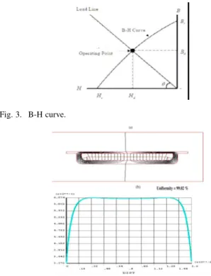
(3) where is the magnetic intensity of the magnet at operating point, while is the thickness of the magnet. The aforemen-tioned operating point is determined based on the magnetization curve (B-H curve) of the magnet, which is shown in Fig. 3. This point is the intersection between the B-H curve and load line, which has an inclination angle determined by
(4)
where is the leakage flux coefficient, is the reluctance coefficient, is the cross-section area of air gap, is the
Fig. 3. B-H curve.
Fig. 4. (a) Calculated magnetic flux. (b) Uniformity of flux density.
area of the magnet, and is the thickness of the air gap. Based on the final simplified circuitry in Fig. 2(b), the total magnetic flux can be obtained by
(5)
The flux through the air gap is part of the previous flux not re-maining in the magnet, which can be calculated by
(6)
where is as defined in Fig. 2(a). Thus, the magnetic flux density through the air gap can be calculated by
(7)
Following the previously proposed computation procedure based on equivalent circuitry, the magnetic flux density in the air gap is obtained as 0.6183 Wb/m .
B. Finite Element Modeling
Utilizing the software ANSYS, the magnetic flux density through the air gap is calculated for validating the computa-tion results based on equivalent circuitry in Seccomputa-tion III-A. This starts with modeling the VCM system with two different types of elements: low-order PLANE13 for most area and high-order PLANE53 for relatively complicated geometry. The resulting flux is shown in Fig. 4(a), with which the flux density can be calculated along the air gap. Fig. 4(b) shows this calculated , where it is seen that the nonlinearity along the gap is only 0.98% (uniformity is 99.02%). It is also seen from Fig. 4(b) that the averaged value of flux density calculated by ANSYS is 0.6074 Wb/m , which is close to previous intensity of 0.6183 Wb/m calculated by equivalent circuitry. This closeness and
CHAO AND WU: OPTIMAL DESIGN OF MAGNETIC ZOOMING MECHANISM USED IN CAMERAS 2581
TABLE I
DESIGNVARIABLES, CONSTRAINTS FORGA,ANDRESULTS
low nonlinearity justifies well the adoption of method of equiv-alent circuitry for ensuing optimization.
IV. OPTIMALDESIGN
Optimization is performed to determine sizes of key parts of the zooming mechanism. This optimization process consists of two steps—problem formulation and employment of GA. The formulation starts with defining the sensitivity of VCM as the fitness function to maximize, with the aim of minimizing trav-eling times of lens holders. The sensitivity is in fact the ratio of square of holder acceleration over the applied power by VCM, i.e.,
(8)
where is the electromagnetic force generated by the VCM, is friction, is the total mass of moving parts in VCM, is the applied voltage, and is the resistance of VCM coils. In (8), the electromagnetic force can be derived via
(9)
where is number of coil loops, is yoke width, is wire diameter of coils, is coil conductivity, and are width and height of holders, respectively; the coil resistance can be de-rived by
(10)
and, finally, the total mass can be derived by
(11) where and are masses of lens and holder, re-spectively, is diameter of holder, is thickness of holders, and are width and height of yoke holes, and is radius of lens. Incorporating (9)–(11) into (8) and having the magnetic flux density by previous equivalent circuitry or fi-nite element analysis (FEA), the sensitivity, the fitness function to be maximized by GA, can be computed.
With the computation procedure established for the fitness function, the next step is to choose the least number of inde-pendent component dimensions possible as the design variables for optimization and determine their constraints. To this end, the following are true: 1) The dimensions related to lens unit are fixed, not defined as design variables, and 2) no physical
in-TABLE II TRIALS FORGA OPTIMIZATION
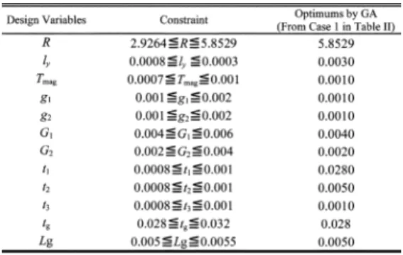
terference is allowed. A thorough investigation leads to the re-sult that 12 independent design variables chosen and their con-straints are determined, as listed in Table I, where is defined by (10), is thickness of magnet, and s, s, s, and s are defined by Fig. 1(b) and (c).
GA [6] is applied to find the optima of predefined design vari-ables. The GA starts with representing the value of each design variable by an array of eight binary bits, and having popula-tion of 50 or 100 to enable crossover operapopula-tions and mutapopula-tion between generations. Different populations are chosen to ob-serve its effects on GA optimization. The crossover and mu-tation rates are set as 0.9 and 0.4, respectively. The maximum number of generations for evolution is set as 10 000 initially and is then decreased to the required number for computation effi-ciency. Table II gives the results from nine different GA opti-mization trials. It is seen from this table that they all converge within preset maximum number of generations, confirming that the results obtained in Table II are truly optima. Furthermore, the optima obtained by GA and shown in Table II lead to al-most the same optimum sensitivity (close to 29 024) and corre-sponding optimal values of design variables, except for trial 2 with a short generation of 1000, which does not give reliable re-sults. The obtained optimal values of design variables are listed in Table I, where it is clearly seen that the optima are in fact at their corresponding extremes in preset constraints.
V. CONCLUSION
A small-sized electromagnetic mechanism for optical zooming in mobile phones is designed and optimized by GA. The results show that design variables of various dimensions reach optima at their extremes inside preset constraints, and, high uniformity of the magnetic flux intensity along guide ways of the VCM is also accomplished.
ACKNOWLEDGMENT
This work was supported in part by the National Science Council of Taiwan under Grant 95-2745-E-033-004-URD.
REFERENCES
[1] K. Hideo, “Mobile phone with zoom lens,” Japan Patent JP2003309756, Apr. 2002.
[2] M. Saka and K. Takamoto, “Zoom lens system,” USA Patent USP5268793, Jan. 1993.
[3] H. Takeuchi, “Zoom lens,” USA Patent USP0248854, Apr. 2005. [4] A. Nikaido, “Linear motor,” USA Patent USP4678951, Nov. 1984. [5] S. Wachi, “Linear motor,” USA Patent USP5121016, Jun. 1991. [6] M. Mitchell, An Introduction to Genetic Algorithms. Cambridge,
MA: MIT Press, 1998.
Manuscript received October 30, 2006; revised February 5, 2007 (e-mail: [email protected]).