國
立
交
通
大
學
資訊學院 資訊學程
碩
士
論
文
具壅塞控制能力之低延遲分散式分時多工無
線隨意網路存取協定
A Low-delay Distributed TDMA Protocol with Congestion
Control for Wireless Ad Hoc Networks
研 究 生:林福龍
指導教授:簡榮宏 教授
具壅塞控制能力之低延遲分散式分時多工無線隨意網路
存取協定
A Low-delay Distributed TDMA Protocol with Congestion
Control for Wireless Ad Hoc Networks
研 究 生:林福龍
Student :Fu-Lung Lin
指導教授:簡榮宏 Advisor :Rong-Hong Jan
國 立 交 通 大 學
資訊學院 資訊學程
碩 士 論 文
A Thesis
Submitted to College of Computer Science National Chiao Tung University in Partial Fulfillment of the Requirements
for the Degree of Master of Science
in
Computer Science
June 2013
Hsinchu, Taiwan, Republic of China
I
具壅塞控制能力之低延遲分散式分時多工無線隨意網路
存取協定
研 究 生:林福龍
指導教授:簡榮宏 教授
國 立 交 通 大 學 資訊學院 資訊學程碩士班
摘 要 在無線通訊技術中,減少訊息傳輸延遲是一項重要的議題。特別是對於傳輸 延遲敏感度高的應用更是格外重要。因此,近來許多智慧型運輸系統 ( Intelligent
Transportation System, ITS ) 的安全應用,對於傳輸延遲也有著嚴格的要求。 現有
的無線網路媒體存取控制( Medium Access Control, MAC ) 協定,大致上可分成:
競爭模式(Contention-based)及排程模式(Schedule-based)兩大類。然而競爭模
式的MAC隨機存取機制,在網路密集度很高的時候,常會產生嚴重的爭用情形。
另一方面,排程模式採取的是有限的延遲(bounded-delay)存取機制,其透過將
時間分割以及排程藉以達到無競爭傳輸。在密集的網絡中,node 數量可能會超 過每一frame 原先所規劃的 slot 數量,導致有 node 無法取得屬於自己的傳輸 slot,因而無法進行訊息傳送。 雖然使用較大的frame size 將允許更多 nodes 無競 爭傳輸,但每一個 node 須花費較長的時間來等待下一次傳送週期,而產生較大 的傳輸延遲。
在本文中,我們致力於結合排程模式 MAC 與功率控制技術,以避免通道擁 塞,並同時保持較低的傳輸延遲。
關鍵字:車載隨意網路(Vehicular ad hoc networks),分散式分時多工( distributed TDMA),功率控制( power control ) 。
A Low-delay Distributed TDMA Protocol with Congestion
Control for Wireless Ad Hoc Networks
Student: Fu-Lung Lin Advisors: Dr. Rong-Hong Jan
Degree Program of Computer Science
National Chiao Tung University
ABSTRACT
Reducing transmission delay is an important issue in wireless communications. It is particular critical to delay-sensitive applications. Many recent safety applications in Intelligent Transportation System (ITS) also have strict requirements on the delay.
Existing Media Access Control (MAC) protocols for wireless networks typically fall into two categories: Contention-based and Schedule-based MACs. However, due to the random access nature, contention-based MAC may incur severe contention, especially in high density networks. Otherwise, schedule-based MAC achieves bounded-delay access by dividing time into frames and let each frame contain several slots for collision-free transmissions. However, in a dense network, the number of nodes could exceed the frame size such that some node may not be able to reserve a free slot for its transmission. A larger frame size will allow more nodes to reserve a free slot for their transmissions, but it may also incur a larger delay since each node has to wait for a longer period of time before the next frame coming.
In this paper, we aim to combine schedule-based MAC with an adaptive power control technique to avoid channel congestion and at same time to retain a lower end-to-end delivery delay.
誌 謝 首先由衷感謝指導教授 簡榮宏 博士, 在這幾年不厭其煩的在學術研究時 指點我正確的研究方向與方法,並提供了完善的學習資源,使我在這些年中獲益 匪淺。 另外,要感謝口試委員:陳健教授、易志偉教授、以及 曾惠如 博士, 在口試時的指導與建議,讓我的論文內容可以更加完善。 同時要感謝安凱學長,在研究過程中問題的探討與協助,讓我少走很多冤枉 路, 並 給 予 實 質 的 建 議 與 幫 助 , 在 我 遇 到 瓶 頸 及 難 題 時 , 及 時 伸 出 援 手 ,使的論文能更順利的進行。 最後要感謝我的太太 貞吟,一路以來的支持、鼓勵、體諒與包容,及不辭 辛勞地照顧家人與小孩,讓我能堅持到最後。僅以本文獻給所有關心我的朋友, 尤其是我最摯愛的家人。 林福龍 僅誌於交通大學 計算機網路實驗室
Contents
Chapter 1 Introduction ... 1
Chapter 2 Related Works ... 4
Chapter 3 Preliminaries ... 8
3.1 Basic Operation of RR-ALOHA ... 8
3.2 Slot Congestion Problem ... 9
3.3 How Power Adjustment Diminishes Slot Congestion ... 11
Chapter 4 Protocol Design ... 14
4.1 Main idea ... 14
4.2 Extended Frame Information ... 15
4.3 Adaptive Power Control ... 16
4.4 How to maintain network Connectivity ... 19
4.5 How to handle in symmetricity ... 21
4.6 PC-ALOHA Protocol ... 22
Chapter 5 Simulation Results and Analysis... 29
5.1 Simulation Environment ... 29
5.2 Results Analysis ... 29
List of Figures
Figure 1. An example of slot reservation with frame size 6... 9
Figure 2. A scenario where slots are congested. ... 10
Figure 3. A scenario of network partition due to the lack of a free slot. ... 11
Figure 4. Node A adjusting its transmission power to achieve a slot ... 11
Figure 5. The power level is too larger. ... 12
Figure 6. The power level is too smaller. ... 13
Figure 7. The power level is too smaller and node A disconnect to other nodes. 13 Figure 8. Adjust the congestion node A power levels. ... 15
Figure 9. Information recorded in EFI. ... 16
Figure 10. channel congestion at node A ... 18
Figure 11. Controlling power for channel congestion at node A ... 19
Figure 12. Points u and v are Gabriel neighbors. ... 20
Figure 13. Points u and v are not Gabriel neighbors. ... 20
Figure 14. Network topology of RR-ALOHA MAC protocol ... 21
Figure 15. Network topology of PC-ALOHA MAC protocol ... 21
Figure 16. Network symmetricity ... 22
Figure 17. Operation of PC-ALOHA at each slot timer Protocol ... 23
Figure 18. Operation of EFI sending routine Protocol. ... 23
Figure 19. Operations at the reception of an EFI Protocol ... 24
Figure 20. Power Control of congestion node Protocol. ... 24
Figure 21. PC-ALOHA flow chart ... 26
Figure 22. Reserved slot of each node ... 28
Figure 23. Frame size vs. Reserving rate ... 30
Figure 24. Reserving rate ... 31
Figure 25. average transmission range ... 31
Figure 26. Convergence (50 Nodes) ... 32
List of Tables
Table 1. EFI table. ... 16
Table 2. Symbol table. ... 17
Table 3. Controlling power for channel congestion at node A ... 19
Chapter 1
Introduction
Reducing transmission delay is an important issue in wireless communications. It
is particular critical to delay-sensitive applications, such as Cooperative Collision
Avoidance (CCA) in vehicular networks [1] in which the front vehicle provide earlier
warning to the backward vehicles by forwarding emergent messages hop-by-hop in
order to avoid the chain-car collision. Providing a low-delay or even delay-bound
protocol can significantly improve the road safety. Many recent safety applications in
Intelligent Transportation System (ITS) also have strict requirements on the delay.
Existing Media Access Control (MAC) protocols for wireless networks typically
fall into two categories: Contention-based and Schedule-based MACs [2]. The
contention-based MAC allows network nodes to randomly access the same radio
channel without pre-coordination among the nodes. Any colliding node goes through
a random binary back off time before the next contention, e.g. the CSMA/CA
mechanism in IEEE 802.11 and WAVE/DSRC MACs[3]. A contention-based MAC
has better channel reusability if the contention among nodes is below certain level [4].
However, due to the random access nature, it may incur severe contention, especially
in high density networks. Besides, strategies like RTS/CTS are usually used to avoid
hidden terminal nodes in contention-based protocols, which however, is not
applicable to broadcast transmission that has a vital role in Vehicular Ad Hoc
Networks (VANETs). Although numerous contention-based protocols were designed
to mitigate the access delay in probabilistic senses [1, 5, 6], they cannot guarantee a
Schedule-based MAC is a kind of Time Division Multiple Access (TDMA) that
offers an inherent collision-free scheme by assigning unique time slots for every node
to send or receive data. For instance, the MAC protocols in [7, 8], [9-13] achieve
bounded-delay access by dividing time into frames and let each frame contain several
slots for collision-free transmissions. Moreover, the hidden terminal problem can be
implicitly resolved if the slots were allocated according to two-hop information
among nodes [9]. It means that a reliable broadcasting at MAC-layer can be easily
achieved in a schedule-based protocol.
However, in a dense network, the number of nodes could exceed the frame size
(i.e. number of slots in each frame) such that some node may not be able to reserve a
free slot for its transmission. It is the so called congestion problem [14]. Furthermore,
if too many nodes cannot obtain slots, the whole network could be partitioned or even
disconnected. This problem is particularly important in vehicular environments where
vehicles density may concentrate at some areas, e.g. toll station, and at picking hours,
and the messages loss due to the lack of a free slot could incur a deadly car accident.
A number of researches have devoted to resolve the congestion problem by
adjusting the frame size according to node density [12]. A larger frame size allows
more nodes to reserve a free slot for their transmissions, i.e. a larger capacity, but it
may also incur a larger delay since each node has to wait for a longer period of time
before the next frame coming. The impact could be more significant to the end-to-end
transmission, where packets will be relayed through multiple hops the destination,
incurring a larger end-to-end delay. Contrarily, a smaller frame size has a lower delay,
but some nodes may not be able to reserve a free slot when all slots in a frame were
reserved, i.e. channel congestion occurs. So, there is a tradeoff between channel
congestion and transmission delay problems.
control technique to avoid channel congestion and at same time to retain a lower
end-to-end delivery delay. More specifically, by reducing the transmission range of
nodes, the proposed protocol tries to maintain a smaller frame size, which is sufficient
for all nodes to make a successful slot reservation, in order to reduce the waiting time
at each relay node. Moreover, our protocol guarantees the network connectivity even
if transmission range of some nodes were reduced. Experimental results show that our
protocol decreases at most 28% in delay.
In the rest of the paper is organized as follows: In Section 2, we give an
overview of schedule based MACs and introduce related works. Existing power
control mechanisms for channel congestion problem are also discussed. In Section 3,
we introduce a well-known schedule-based MAC protocol and discuss how power
control technique avoids channel congestion problem. Then, our MAC protocol is
presented in Section 4. In Section 5, we evaluate the performance of our protocol
Chapter 2
Related Works
Reservation ALOHA (R-ALOHA) [15] is a well-known distributed TDMA
protocol. It divides channel access time into slots and allows each node contending to
reserve an available slot and using the slot in subsequent frames as long as the node
has packets to send. However, R-ALOHA has a potential risk of collision problem if
hidden nodes exist.
Borgonovo et al. [13] proposed an improved protocol, called Reliable R-ALOHA
(RR-ALOHA), to overcome the hidden terminal problem. In RR-ALOHA, when a
node enters the network, it listens to the slots occupation for an entire frame, and
broadcasts a Frame Information (FI) on an un-used slot to reserve a own slot. Then,
the node listens to the FI from its one-hop neighbors for one complete frame to get the
slot occupation information within the range of its two hops, and can successfully
reserve the slot if there is no other node reserving the same slot. Later, the authors
incorporated the RR-ALOHA with an optimal multi-hop broadcast service and
parallel transmissions [9]. The protocol, called ADHOC-MAC, uses a small number
of relaying terminals to cover all nodes in the network so as to eliminate the broadcast
retransmissions.
The authors in [12] proposed an adaptive MAC protocol for wireless vehicular
network base on ADHOC MAC, called Adaptive ADHOC (A-ADHOC). The protocol
implements a mechanism supporting an adaptive frame length. Every node tries to
send out a specific message to double (or halve) the frame length, when the number of
words, the congestion problem can be resolved by adaptively changing the frame
length at each node. However, the relaying time could be prolonged at some node
having a longer frame length, which in turn, cause a larger end-to-end delivery delay.
A number of studies have suggested integrating dynamic TDMA for vehicular
networks [8, 10, 11]. Federal Communication Consort (FCC) allocates 75MHz
bandwidth at 5.9GHz spectrum for Wireless Access Vehicle Environments
(WAVE)[3]. The bandwidth is divided into seven channels, including a control
channel (CCH) and six service channel (SCHs). IEEE 802.11p/1609 further divides
the channel access time into a CCH interval and a SCH interval for multi-channel
operations. Nodes can content for the control channel to exchange control or emergent
messages on control channel at CCH interval, and transmit non-safety messages on
service channels at SCH interval. Although WAVE is specifically defined for efficient
message disseminations in VANETs, research evidences showed that its
contention-based nature may lead to a severe collision especially on the control
channel.
Lu et al. proposed a dedicated multi-channel MAC (DMMAC) with adaptive
broadcasting [11]. It further divides the CCH into an Adaptive Broadcast Frame (ABF)
and a Contention-based Reservation Period (CRP). In the duration of ABF, each node
tries to content the free slot for receiving or sending the FI frames based on
RR-ALOHA. Similar to A-ADHOC, DMMAC can dynamically increase the number
of time slots in ABF, called ABF Length (ABFL), when CCH is congested. However,
it may also cause a larger end-to-end delay if the ABFL is longer.
The VeMAC [8] further divides the CCH into several time slots and assigns
disjoint sets of time slots to vehicles moving in opposite directions and to Road Side
Units (RSUs). It can avoid merging collision that happens when two vehicles are
authors showed that for the same number of contending nodes and available time slots,
nodes can acquire slots on the CCH more efficiently.
Ning Lu et al. [10] propose a MAC protocol similar to RR-ALOHA, called the
Distributed Reliable Multi-channel MAC (DR-MMAC). They showed that packet
delivery ratio of the IEEE 802.11p MAC drop drastically when the number of
vehicles is greater than 10, because of the contention in control channel and hidden
terminal problem. DR-MMAC can guarantee 100% delivery ratio. But the results also
indicate that the delivery ratio could decrease if too many vehicles join the network,
since the number of nodes may exceeds the frame size.
The VeSOMAC [7] is a location-aware schedule-based MAC for VANETs. It
achieves delay reduction by temporally order the slots according to the sequence of
vehicles entering on the road. In this way, messages can be quickly forwarded to the
front or rear vehicles within the same frame if slots were properly ordered, providing
better vehicle safety.
A number of contention-based MAC protocols [4, 5, 17, 18, 19, 20] were
designed to avoid congestion, i.e. traffic load on the wireless channel, by controlling
the transmission power. Torrent-Moreno et al. [4] proposed Fair Power Adjustment
for Vehicular environments (FPAV) algorithm. The main idea is to reserve a chunk of
bandwidth for event driven message so that communication of safety applications is
not hindered by channel saturation. But, it needs central entity presence at all
locations. In further study [18], the same authors proposed a “distributed” algorithm
in which each collects status information and exchanges power level to overcome the
drawbacks of FPAV. However, it suffers from a huge overhead when relaying
information. Mittag et. al [19] improve the overhead in Distributed Fair Power
Adjustment for Vehicular networks (D-FPAV) by exchanging the number of vehicles
maintaining a low connectivity in a dense network (e.g., only communicate with the
closest neighbors) for reducing packet collisions. The above protocol can mitigate
channel congestion and delay by power control, but it still can not guarantee a lower
or even bounded access delay.
To the best of our knowledge, there was no schedule-based MAC protocol
resolving the congestion problem and at the same time achieving a lower delay. Our
research is based on the perspectives: Combining schedule-based MAC with a power
Chapter 3
Preliminaries
This chapter first introduces the RR-ALOHA protocol. Next, we discuss what
would happen if the channel is congested. Then, we introduce the main idea of our
protocol and discuss the challenges when designing the protocol.
3.1 Basic Operation of RR-ALOHA
Suppose that there are N slots in one frame, and there are M nodes trying to
contend for their slots. Each node shares the slot occupation information from its
one-hop neighbors to each other. When a node enters the network, it listens to the
slots occupation for an entire frame, and broadcasts a FI on an un-used slot to reserve
the slot. Then, the node listens to the FI from its one-hop neighbors for one complete
frame. If all FIs from its one-hop neighbors received by node i in last frame are
marked as “Slot j is BUSY by node i”, this contending is successful and node i will
use the slot j in subsequent frames as long as the node has packets to send. Otherwise,
node i needs to re-contend in next frame, because some nodes of its one-hop
neighbors did not receive the FI of node i.
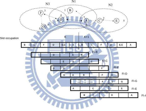
As shown in Figure 1, the frame size is 6. Nodes D, F and G are one-hop
neighbors and form a fully connected network. Similarly, nodes A, B and D as well as
node A, C and E are two groups of one-hop neighbors. If node A wants to join the
network, it listens to the FIs from its one-hop neighbors, i.e. nodes B, C, D and E.
After listening to the FIs, node A knows that slots 1, 2, 4 and 5 are used, respectively,
by nodes B, C, D and E, and it can get the slot occupation information of its two-hop
a result, node A will find that slot 6 is free. When slot 6 comes, node A transmits its
FI at slot 6. When successfully transmitted the FI packet, node A waits six slots. If all
FIs from its one-hop neighbors (i.e., nodes B, C, D and E) indicates that slot 6 was
marked as BUSY by node A, slot 6 is successfully reserved and will be used for the
subsequent transmissions by node A.
A C F E D B G N1 1 3 5 4 2 5 6 N2 N3 B A D A B D A E,G D F C B A E,G D F C B C F D E,G A B C F D E,G A B FI-B C A E A C E FI-C F G D G F D FI-F D F B A G A B F D G FI-D G D F D G F FI-G A D C B C D A B FI-A E C A C E A FI-E Slot occupation K K+1
Figure 1. An example of slot reservation with frame size 6.
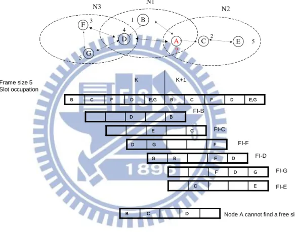
3.2 Slot Congestion Problem
The above process goes well if all nodes can reserve their slots. But, what would
happen when the channel (slot) congestion in a dense network? (i.e., N < M). As
shown in Figure 2, there are 7 nodes contending for 5 slots. Assume that nodes B, C,
cannot transmit its FI since there is no more free slot (i.e., after node A listened to the
FIs from its one-hop neighbors, node A finds that all slots were reserved). In this case,
node A has neither the right to transmit nor the guarantee of receiving packet from all
its neighbors. In other words, node A does not join to the network.
A C F E D B G N1 1 3 5 4 2 5 ? N2 N3 B D B D FI-B FI-C FI-F FI-D FI-G FI-E Frame size 5 Slot occupation K K+1 E,G D F C B E,G D F C B C F D E,G B C F D E,G B C E C E F G D G F D D F B G B F D G G D F D G F E C E C D C B C D
B Node A cannot find a free slot
Figure 2. A scenario where slots are congested.
Even worse, the network could be partitioned if some critical node did not join
the network. As shown in Figure 3, node A is the only node bridging networks N1 and
N2, and it cannot forward any packet from node C or node E to nodes B and D,
because it did acquire a free slot. Similarly, any packet from node B or node D cannot
A C F E D B G 1 3 5 4 2 5 N2 N3 N1 X X
Figure 3. A scenario of network partition due to the lack of a free slot.
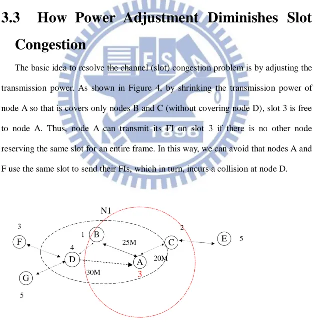
3.3 How Power Adjustment Diminishes Slot
Congestion
The basic idea to resolve the channel (slot) congestion problem is by adjusting the
transmission power. As shown in Figure 4, by shrinking the transmission power of
node A so that is covers only nodes B and C (without covering node D), slot 3 is free
to node A. Thus, node A can transmit its FI on slot 3 if there is no other node
reserving the same slot for an entire frame. In this way, we can avoid that nodes A and
F use the same slot to send their FIs, which in turn, incurs a collision at node D.
A C F E D B G N1 30M 25M 20M 1 3 5 4 2 5 3
3.4 Challenges
From the above example, we can see that reducing the transmission power can
improve the spatial re-use in the network and resolve slot congestion. However, how
to determine the transmission power for congested nodes? Such as the case in Figure
5, the default power is 35 meters. Suppose that node A adjusts its transmission power
from 35 to 34 meters, the slot congestion problem still exists, since the power range
remains too large to infer with other nodes. On the other hand, if node A reduces its
transmission range to 24 meters, the transmission range is too smaller. As shown in
Figure 6, it may cause a larger end-to-end delivery delay. When node A broadcast a
message, node F receives the message four hop counts later (i.e., A -> C -> B -> D ->
F). But, the best path should be A -> B -> D -> F. Even worse, node A will disconnect
to other nodes if node A adjusts its transmission range below 20 meters as shown in
Figure 7. After adjusting power levels it must create unidirectional links (i.e., a lower
power node might not be received at a higher power node). Such as that node A can
receive FI from nodes B, D, but nodes B, D cannot receive FI from node A as shown
in Figure 6. These are the significant challenges what need to overcome.
A C F E D B G N1 30M 25M 20M 5 3 4 1 2 5 3
Default power range
A C F E D B G N1 30M 25M 20M 1 3 5 4 2 5 3
Figure 6. The power level is too smaller.
A C F E D B G N1 30M 25M 20M 5 3 4 1 2 5 3
Chapter 4
Protocol Design
In this chapter, we present the Power-Control ALOHA (PC ALOHA). First, we
describe the main idea that how we control the power. Then, we define a unique data
structure, called Extended Frame Information (EFI) in our protocol. After that, an
adaptive power control mechanism is presented. We also discuss how we handle the
symmetric and connectivity problem in our protocol. The algorithm of PC-ALOHA is
summarized in the last part.
4.1 Main idea
In the Chapter 3, we have observed that a node can reserve a reserved slot if
reducing the power so that a receiving node will not be interfered by the two nodes
and the most challenging problem is to determine the transmission power for the
congestion nodes.
Our goal is to reduce the power for congested nodes with the least increment to
the frame size, i.e. the least increment to the end-to-end delay. The main idea is
explained as follows: As a node is congested, we intend to reduce the least amount of
the node’s transom power such that any transmission from the node will not interfere
to any neighboring node at a certain slot. At the same time, we avoid the network be
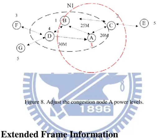
partitioned to different groups. As shown in Figure 8, it is sufficient to obtain a free
we select to re-use slot 3, because there aren’t any one-hop neighbors use the slot 3. In
this way, it has the least reduction of power, which avoids the possibility of increasing
end-to-end delay when node A wants to broadcast a message to its neighbors.
Figure 8. Adjust the congestion node A power levels.
4.2 Extended Frame Information
To discover the possible spatial reusability according to the positions
additionally carried in the FI, called extended FI (EFI). The content of FI is shown in
Figure 9. ID indicates the identifier of the node that sends this FI. Length indicates the
FI packet length. X, Y, Z indicates the X, Y, Z coordinate system information from
Global Positioning System (GPS). Slot Information (SI) contains the status (FREE or
Figure 9. Information recorded in EFI.
Each node will maintain an EFI table includes the slot status, distance to the
one-hop node, and which node is using the slot as shown in Table 1. We establish a
definition as:
Definition: A slot can be recorded as “FREE”, “BUSY by node i” or “RESERVED
by node i” by node j:
1. “BUSY by node i”: When node j receives the FI from node i, and the information will be written into its broadcasting EFI.
2. “RESERVED by node i”: The information come from its one-hop neighbors. It means that a two-hop neighbor has occupied this slot, so node j cannot contend for this slot or collisions may happen somewhere. And Node j won’t write this record into its broadcasting EFI.
3. “FREE”: The slot is free. Node j can contend for this slot.
slot 1 2 3 4 5
id B C D E
status BUSY BUSY FREE BUSY RESERVED
distance 25m 20m 30m 20
Table 1. EFI table.
4.3 Adaptive Power Control
Before we present how reservation works, we should present some definitions as
i
V :the node i
ij
D :Distance from node i to node j
OH :One-hop member
TH :Two-hop member
OH
S :Slot using by one-hop member
TH
S :Slot using by twp-hop member
P
:The minimum amount of power range decreaset adj
P :The transmission power range after adjusting
t
Pmax :The node maximum transmission power range
r ji
D :The distance from the transmission node j to received node i
Table 2. Symbol table.
The node V join the network, if i V can find a FREE slot from (i SOH STH), send the EFI on the FREE slot. Otherwise, when the channel is congestion (i.e., V i
cannot find any more FREE slot from EFI table, we can choice a STH slot that can
make its own EFI table as FREE through shrinking the transmission radius as
P D
Padjt ij . Now, V can contend for the FREE slot. After adjusting power range, i
it will create unidirectional links. The V must maintain the EFI table carefully. i
When V receives an EFI from i Vj, V must take care about the i r ji D between two nodes. If V finds i r ji t adj D
P , V still need mark i SOH as BUSY. But, V must i
mark STH as FREE. However, two different OHs maybe share the same STH
information at same time, we just record the Min{Drji,Dkir } in the EFI table. Where
A C F E D B G N1 1 3 5 4 2 5 30 M 25 M 20M slot 1 2 3 4 5 id B C F D E, G
status BUSY BUSY RESERVE BUSY RESERVE
distance 25m 20m dist to D
30m 30m
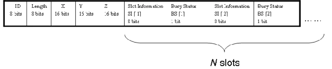
dist to C 20=min{20, 30} Figure 10. channel congestion at node A
As shown in Figure 10, the frame size is 5. Node A receives the EFI from its one
hop members (i.e., B, C and D) and maintains its own EFI table. Node A cannot
transmit its EFI since there is no more free slot. Before node A adjusts its
transmission power, node A selects a RESERVED slot 3 (or 5) to send its EFI with
maximum transmission power 35 meters, node A will incur a collision at D (or C).
As shown in Figure 11 and Table 2, the slot 3 is only used by two-hop member
(i.e., node F). After node A adjusts power range to 30 -
P
meters, node A can markthe slot 3 as FREE as shown in Table 2 and then node A can send its EFI at slot 3
without colliding at node D. At same time, node A still marks slot 4 as “slot 4 BUSY
Figure 11. Controlling power for channel congestion at node A
slot 1 2 3 4 5
id B C D E, G
status BUSY BUSY FREE BUSY RESERVE
distance 25m 20m 30m dist to C
20=min{20, 30} Table 3. Controlling power for channel congestion at node A
4.4 How to maintain network Connectivity
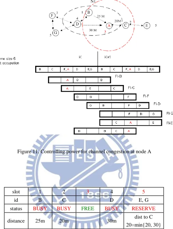
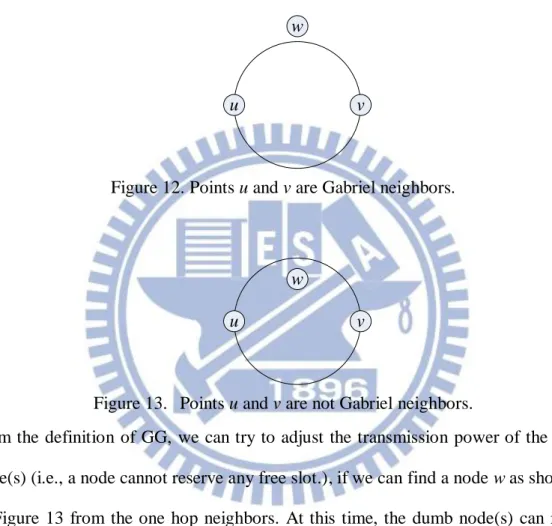
The Gabriel Graph (GG) is a connection scheme proposed by Gabriel and Sokal
(1969) [22], two points are connected when the circle associated with the diameter
that has the two points as endpoints does not have another point within its
circumference. Mathematically, the GG is defined as follows: An edge
u,v exists between vertices u and v if no other vertex w is present within the circle whosediameter is uv . In equational form : wu,v: 2 2 2
vw uw uv d d
d . As shown in
Figure 12, points u and v are Gabriel neighbors. Otherwise, the presence of point w
within the circle prevents points u and v from being Gabriel neighbors as shown in
Figure 13.
u v
w
Figure 12. Points u and v are Gabriel neighbors.
u v
w
Figure 13. Points u and v are not Gabriel neighbors.
From the definition of GG, we can try to adjust the transmission power of the dumb
node(s) (i.e., a node cannot reserve any free slot.), if we can find a node w as shown in
in Figure 13 from the one hop neighbors. At this time, the dumb node(s) can re-use
the time slot(s) and maintain network connectivity at same time. The significant
difference between Figure 16 and Figure 17 is that we can guarantee the network still
connectivity when frame size is 5. For our application, the algorithm should be run in
a distributed fashion by each node in the network, where a node needs information
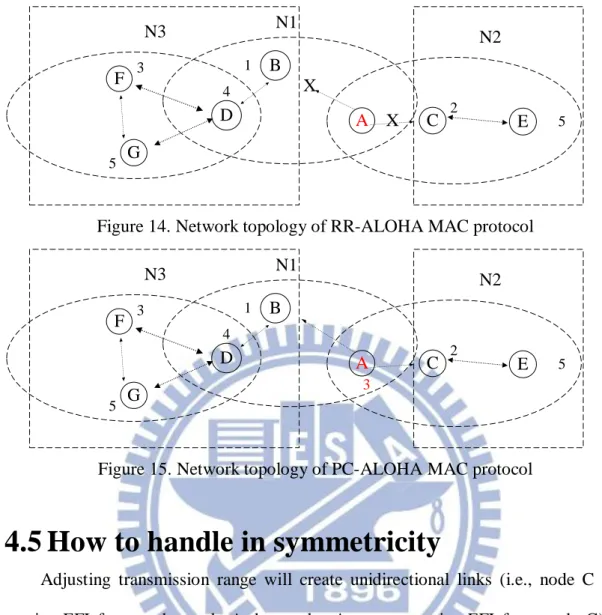
A C F E D B G 1 3 5 4 2 5 N2 N3 N1 X X
Figure 14. Network topology of RR-ALOHA MAC protocol
A C F E D B G 1 3 5 4 2 5 N2 N3 N1 3
Figure 15. Network topology of PC-ALOHA MAC protocol
4.5 How to handle in symmetricity
Adjusting transmission range will create unidirectional links (i.e., node C can
receive EFI from nodes node A, but nodes A cannot receive EFI from node C) as
shown in Figure 16. When the new join node A try to reserve slot 5 for sending the
EFI and the power range can cover to C, because it cannot get any slot status from C’s
EFI(i.e., A cannot know E exist.). At this time, both nodes A and E would transmit
their EFI at slot 5 that incur a collision at C (i.e., C’s EFI will mark the slot 5 as FREE,
because it cannot receive any EFI at slot 4 in last frame). Then, E will find one EFI of
its one-hop neighbor(s) don’t mark slot 5 as “BUSY by node E”. Now, node E will
detect that incur a collision at somewhere. Node E just need to re-entrance the
Figure 16. Network symmetricity
4.6 PC-ALOHA Protocol
We summarize the above describe into a series of protocols the main operation of
PC-ALOHA at each slot when node join the network, operation of EFI sending and
receiving routine, and Power Control of congestion node in Figure 17~20. And the
PC-ALOHA flow chart has shown in Figure 21.
Protocol 1: Operation of PC-ALOHA at each slot timer Protocol: /* parameters and Flag defined
WAITING : waiting to contend for a slot CONTENDING : occupation or contending for a slot Status : status of the node
*/
1 if node is waiting to contend for a slot then 2 if the coming slot is free then 3 if I try to contend it then 4 send the EFI. call sendFI ()
5 set Status=CONTENDING of the node
6 else A C F E D B G N1 1 3 5 4 2 5 5 2
☆
7 reset Timer of the node
8 set Status=CONTENING of node 9 for ( i = 0; i < TOTAL_SLOT; i ++)
10 check the free slot 11 if no more free slot then
12 select transmission power. call SelectPowerRange( )
13 Timer of system++
14 return
15 else if my contending slot is coming then
16 if there isn’t any collision (feedback from receive algorithm) then 17 send the EFI call. call sendFI()
18 set Status=CONTENDING of the node
19 return
20 else // Collision
21 Set Status=CONTENDING of node and contend for slot again. 22 reset Timer of the node
23 Timer of system++
24 return
25 else
26 Timer of system++
27 receive EFI and maintain EFI table only
28 return
Figure 17. Operation of PC-ALOHA at each slot timer Protocol
---
Protocol 2 Operation of EFI sending routine: ---
/*
Parameters and Flag defined */
1 if my contending slot is coming then
2 send the EFI packet by transmission power piggybacking my X, Y, 3 and Z coordinate and slot using status of my one-hop neighbors 4 return
---
Protocol 3 Operations at the reception of an EFI ---
/*
Parameters and Flag defined */
1 if my transmission power >= distance to the transmission node then
2 maintain slot status, distance to the transmission node and who 3 use the slot in its EFI table
4 else
5 mark the slot that only using by two-hop neighbors as FREE 6 return
Figure 19. Operations at the reception of an EFI Protocol
---
Protocol 4 Power Control of congestion node ---
/*
Parameters and Flag defined */
1 for (i=0; i < TOTAL_SLOT; i ++)
2 if the slot used by two hop node only then
3 for(j=0; j < TOTAL_SLOT; j ++) 4 check each one-hop neighbor
5 if we can find one-hop node didn’t satisfy GG constraint then
6 set release flag =TRUE 7 else
8 continue
9 else
10 continue
11 if the release flag ==TRUE then 12 adjust my transmission power 13 break
The details of protocol 1 are described as follows:
- line 1: Check if the node is waiting to contend for slot, after listening to the slots
occupation for an entire frame
- line 2~5: If the incoming slot is free and the node try to contend for the free slot.
First, the node must send out an EFI packet and change the node status.
- line 6~8: If the node don’t contend for the incoming free slot, it would wait the next
free slot coming and repeat line 2~5 steps.
- line 9~14: If the node cannot find any free slot, the node can follow the GG
constraint to shrink its transmission power for re-using the reserved slot.
- line 15~24: Check whether all the one-hop neighbors received my EFI. If agree,
sends out the EFI packet at the coming slot again. Otherwise, try to wait another
free slot coming and contend for it.
- line 25~28: Just listening the EFI packets from one-hop neighbors and maintaining
EFI table.
The details of protocol 2 are described as follows:
- line 1~4: Nodes share their perceived information and X, Y, Z coordinate to each
other by properly broadcasting packet EFI.
The details of protocol 3 are described as follows:
- line 1~3: If our power range can cover to the transmission nodes, we will record all
EFI information from one-hop neighbors in EFI table.
- line 4~6: We must consider unidirectional links. When our power range cannot
cover to the transmission nodes, we can mark the slot which using by two-hop
neighbor only as FREE.
- line 1~2: Find out the slot only used by two-hop neighbor from our EFI table
- line 3~6: Find out a one-hop node which didn’t satisfy GG constraint when we
adjust the power range. Then, we can guarantee the network still connectivity.
- line 7~8: Go to next step.
- line 9~10: Go to next step.
- line 11~13: If we can find out the one-hop neighbor, shrink our transmission power
for re-using the reserved slot.
As shown in Figure 23, we demonstrate the flow chart of PC-ALOHA Protocol.
As shown in Figure 2, there are 7 nodes contending for 5 slots. After a listen
interval, each node has to contend to reserve an available slot and use the slot in
subsequent frames. According to our protocol and flow chart, the simulation statuses of
each node shown in Figure 22 and described as follows:
-- In Frame 1:
Node B: Try to send an EFI to contend slot 1 for its transmission, and set up the status
from WAITING to CONTENDING at same time.
Node C: Try to send an EFI to contend slot 2 for its transmission, and set up the status
from WAITING to CONTENDING at same time.
Node F: Try to send an EFI to contend slot 3 for its transmission, and set up the status
from WAITING to CONTENDING at same time.
Node D, G: Try to send an EFI to contend slot 4 for its transmission, and set up the
status from WAITING to CONTENDING at same time. Actually, the EFIs
will collision at node F. In next frame (i.e., frame 2), EFI from its one-hop
neighbor, Node F, does not indicate that slot 4 was marked as BUSY by node
D or G.
Node A, E: Try to send an EFI to contend slot 5 for its transmission, and set up the
status from WAITING to CONTENDING at same time. The EFI will
collision at node C. So, node A and E need to listen a frame interval and
contend a free slot for its transmission again.
-- In frame 2:
Node B, C and F:
The contending is successful and nodes B, C and F will use the slot 1, slot 2
and slot 3 in subsequent frames as long as the node has packets to send.
The contending is unsuccessful. Nodes A, D, E and G have to listen a frame
time and try to reserve a free slot again. All of them must set up the status
from CONTENDING to WAITING at same time.
-- In frame 3:
Node A: It does not contend a free slot for its transmission in frame 3.
Node D: Send an EFI to contend other slot 4 for its transmission, and set up the status
from WAITING to CONTENDING.
Node E, G: Try to wait another free slot 5 coming and contend for it. And set up the
status from WAITING to CONTENDING. Nodes E and G are not two-hop
neighbor, so they will reserve slot 5 for theirtransmission successfully.
-- In frame 4:
Node A: Node A can not find any free slot for its transmission end of frame 3. According to our power control protocol shown in Figure 21, it will find slot
3 can be re-used. All of Node A~G will reserve a slot for their transmission in
subsequent frames
| frame 1 | frame 2 | frame 3 | frame 4 1 2 3 4 5 1 2 3 4 5 1 2 3 4 5 1 2 3 4 5 A T T X T B T T T T C T T T T D T X T T E T X T T F T T T T G T X T T
Figure 22. Reserved slot of each node ☆ ☆ ☆ ☆ listen a frame listen a frame listen a frame listen a frame collision
Chapter 5
Simulation Results and Analysis
5.1 Simulation Environment
In this section, we compare the performance of the proposed PC-ALOHA MAC
protocol with that of RR-ALOHA MAC protocol in ns-2 [23]. The duration of each
simulation is 10 seconds. Each simulation runs 20 times. The data rate is 2 Mbps
(802.11b). All nodes are assumed to be stationary and their maximum transmission
ranges are 250 meters. The EFI frame length is fixed at 80 bytes. The slot time is
fixed at 2ms. The numbers of default nodes are 100 nodes, and the deployment region
is 1000*1000 meters.
5.2 Results Analysis
A). Frame size vs. Reserving rate:
First, the aim of this experiment is to study the reserving rate relate to the frame
size. As shown in Figure 22, the number of nodes is inversely proportional to the
percentage of reserved nodes on RR-ALOHA. On the other word, PC-ALOHA needs
a fewer slots to achieve 100% reserving rate than RR-ALOHA in a dense network. A
larger frame size may incur a larger delay since each node has to wait for a longer
period of time before the next frame coming. Otherwise, the smaller frame size can
update the message more quickly.
0 50 75 100 125 150 0 20 40 60 80 100 120 Number of nodes
Percentage of reserved nodes
Frame size vs. Reserving rate
PC-10 slot PC-20 slot PC-30 slot RR-10 slot RR-20 slot RR-30 slot
Figure 23. Frame size vs. Reserving rate
B) Single-hop performance:
As shown in Figure 23, RR-ALOHA requires 33 slots to achieve 100% of
reserving rate, but PC-ALOHA requires only 28 slots to achieve 100% of reserving
rate. PC-ALOHA can save about 15% frame size (28/33 =84.5%). PC-ALOHA frame
size is smaller than RR-ALOHA, PC-ALOHA has a lower message update delay. It
shows clearly, the slot reserving rate of RR-ALOHA is related to the frames size.
PC-ALOHA always keeps the nodes reserving rate upon 98%. However, it is a
dangerous when the channel is congestion in RR-ALOHA network. Because of many
nodes have neither the right to transmit nor the guarantee of receiving packet from all
its neighbors. In other words, the congestion nodes do not join to the network.
As shown in Figure 24, in order to enhance the slot reserving rate, PC–ALOHA
need to reduce the transmissions range for slot time re-using. If the frame size is
0 22 24 26 28 30 32 34 36 38 40 75 80 85 90 95 100 Frame size
Percentage of reserved nodes
Convergence
RR-100 nodes PC-100 nodes
Figure 24. Reserving rate
Figure 25. average transmission range
C) Convergence :
Although schedule-based MAC protocol can provide each node a contention-free
opportunity for data transmission without collision, the node still need to contend for
slot reservation by using RR-ALOHA or PC-ALOHA. Especially when it comes to
the initialization of the system, in which many vehicles want to reserve a slot. As a 0 10 slot 15 slot 20 slot 25 slot 30 slot 35 slot 0 0.2 0.4 0.6 0.8 1 1.2 average transmission range (100 nodes)
RR-100 nodes PC-100 nodes
result, it may take several frames until all the reservation processes complete.
As shown in Figure 25 and Figure 26, the RR-ALOHA protocol slot reserving
rate almost can upon 100%. It means that the channel is not congestion. So the power
control mechanism did not need to be triggered often. As a result, the PC-ALOHA
will not increase the system convergence overhead compared to RR-ALOHA
protocol. 0 5 10 15 20 25 30 0 10 20 30 40 50 60 70 80 90 100 Number of frames
Convergence (50 Nodes . Frame size :15 Slots)
Percentage of reserved nodes
RR-50 nodes PC-50 nodes
Figure 26. Convergence (50 Nodes)
Figure 27. Convergence (100 nodes)
D) Performance under 100% reserving ratio:
As shown in Table 4, the relationship between slot reserving ratio of nodes and
0 5 10 15 20 25 30 35 0 10 20 30 40 50 60 70 80 90 100 Number of frames
Percentage of reserved nodes
Convergence (100 Nodes . Frame size :30 Slots)
RR-100 nodes PC-100 nodes
the number of frame sizes, average flooding hop counts and number of frame sizes,
and average relaying delay and number of frame sizes in the different network density.
There are two values in each field. Above number in the field presents the average
value and below number in the field presents the maximum one. (e.g., the
RR-ALOHA requires 32 slots upon 100% reserving ratio and the maximum number
of slot is 33. PC-ALOHA only requires 26.2 slots upon 100% reserving ratio and the
maximum number of slot is 28). As a result of the simulation: in the deployment
region, the frame sizes under 100% slot reserving ratio is based on the nodes density.
The results show that the PC/RR ratio of required slots decreases as the number of
nodes increases, since the higher density, the larger frame size is required, which
implies that our approach has more chance to find a free slot by reducing the node’s
power. On the other hand, PC–ALOHA will save a larger percentage of frame sizes in
the high dense networking.
node
Required slots Hop counts Relaying delay (ms)
(Hop count*Frame size)
RR PC PC/RR RR PC PC/RR RR PC PC/RR 50 14.200 (15) 12.666 (13) 0.89 (0.87) 3.328 (3.430) 3.417 (3.529) 1.026 (1.028) 95 (103) 87 (92) 0.915 (0.893) 100 32.000 (33) 26.200 (28) 0.82 (0.85) 2.969 (3.006) 3.027 (3.052) 1.019 (1.015) 190 (198) 159 (171) 0.836 (0.863) 150 46.500 (48) 35.800 (38) 0.77 (0.79) 2.917 (2.988) 3.032 (3.082) 1.039 (1.031) 271 (287) 217 (230) 0.800 (0.801)
Table 4. Performance under 100% reserving ratio
E) Flooding Delay
simulation case (e.g., 100 nodes frame size is 33 in RR-ALOHA, 28 slots in
PC-ALOHA). As shown in Figure 27, (1) in dense networking, RR-ALOHA average
delay is higher than PC-ALOHA. (2) The maximum delay in 150 nodes simulation
case, RR-ALOHA is higher than PC-ALOHA about 28% and the average delay is
about 11%. Therefore, it is a serious issue for safety-critical application message
exchange. 0 50 100 150 200 0 20 40 60 80 100 120 Number of nodes Delay time (ms) Flooding Delay PC-AVG. Delay RR-AVG. Delay PC-MAX. Delay RR-MAX. Delay
Chapter 6
Conclusion
In this paper, we have proposed a low-delay distributed TDMA Protocol with
congestion control for wireless Ad Hoc networks base on previous RR-ALOHA MAC
protocol. The most important features of PC-ALOHA MAC protocol are resolving the
congestion problem and at the same time achieving a lower end-to-end delivery delay
for the Ad Hoc networks. At same time, our PC-ALOHA MAC protocol guarantees
the network connectivity even if transmission range of some nodes were reduced. As
the result, in dense networking, our protocol decreases at most 28% in delay than
RR-ALOHA. It proof our MAC protocol is suitable for the current delay-sensitive
safety application, such as Cooperative Collision Avoidance (CCA) in vehicular
networks. In future, we will further consider how to assign slots to nodes most quickly
Reference
[1] X. Yang, J. Liu, and F. Zhao, “A Vehicle-to-vehicle Communication Protocol for
Cooperative Collision Warning”, In Proceeding of the 1st Annual International
Conference on Mobile and Ubiquitous Systems Networking and Services, IEEE Computer Society, Massachusetts, USA, pp. 114 - 123,2004.
[2] V.S. Raghavan S. Kumar and J. Deng. “Medium access control protocols for ad-hoc wireless networks: A survey.” Elsevier Ad-Hoc Networks Journal, 4(3):
pp. 326 - 358, May 2006.
[3] L. Armstrong, “Dedicated Short Range Communications (DSRC),” [Online].
Available: http://www.leearmstrong.com/dsrc/DSRCHome.htm
[4] M. Torrent-Moreno, P. Santi, and H. Hartenstein, “Fair Sharing of Bandwidth in VANET”, in Proceedings of the 2nd ACM International Workshop on Vehicular
Ad Hoc Networks (VANET), Cologne, Germany, pp. 49 - 58, 2005.
[5] Xu Guan, Raja Sengupta, Hariharan Krishnan, Fan Bai “A Feedback-Based Power Control Algorithm Design Based Power Control Algorithm Design for VANET”, Mobile Networking for Vehicular Environments, pp. 67 – 72, 2007. [6] J. Zang, L. Stibor, et al. “Congestion Control in Wireless Networks for Vehicular
Safety Applications”, In Proceeding The 8th European Wireless Conference, Paris, France. pp. 7, 2007.
[7] Fan Yu and Subir Biswas, “Self-configuring TDMA protocol for enhancing
vehicle safety with DSRC based vehicle-to-vehicle communication”, IEEE
Journal Selected Areas in Communications, vol. 25, no. 8, pp. 1526 – 1537,
2007.
[8] Hassan-Aboubakr Omar, Weihua Zhuang, and Li Li, “VeMAC: A novel
Conf. on Computer Communication Workshop, pp. 413 – 418, 2011.
[9] F. Borgonove, A. Capone, M. Cesana, and L. Fratta, “ADHOC MAC: New MAC
architecture for ad hoc networks providing efficient and reliable point-to-point and broadcast services”, Wireless Networks, vol. 10, pp. 359 – 366, 2004.
[10] Ning Lu, Xinhong Wang, Ping Wang, Peiyuan Lai, Fuqiang Liu “A distributed
reliable multi-channel MAC protocol for vehicular ad hoc networks”, in Proc. of
IEEE Intelligent Vehicles Symposium, pp. 1078 – 1082, 2009.
[11] Ning Lu, Yusheng Ji, Fuqiang Liu, and Xinhong Wang “A dedicated multi-channel MAC protocol design for vanet with adaptive broadcasting”,
WCNC, pp. 1 -6 ,2010.
[12] Jia Liu, Fengyuan Ren, Limin Miao, Chuang Lin “A-ADHOC: an adaptive
real-time distributed mac protocol for vehicular ad hoc network”, ChinaCOM, pp.
1 – 6, 2009.
[13] F. Borgonovo, A. Capone, M. Cesana, L. Fratta, "RR-ALOHA, a Reliable
R-ALOHA Broadcast Channel for Ad Hoc Inter-Vehicle Communication Networks", Med-Hoc-Net, Baia Chia, Italy, 2002.
[14] B. Hull, K. Jamieson, and H. Balakrishnan, “Mitigating Congestion in Wireless
Sensor Networks”, In Proc. of 2nd ACM Conference on Embedded Networked
Sensor Systems, pp. 134-147, November 2004.
[15] W. Crowther, R. Rettberg, D. Waldem, S. Ornstein, and F. Heart, “A System for
Broadcast Communication: Reservation-ALOHA,” in Proceedings of the Sixth
Hawaii International Conference on System Sciences, January 1973.
[16] F. Borgonovo, L. Campelli, M. Cesana, and L. Fratta, “Impact of user mobility on the broadcast service efficiency of the ADHOC MAC protocol”, Proc. IEEE VTC, vol. 4, pp. 2310-2314, 2005.
Communication: Fair Transmit Power Control for Safety-Critical Information”,
IEEE TRANSACTIONS ON VEHICULAR TECHNOLOGY, VOL. 58, NO. 7, pp.
3684 – 3703, 2009.
[18] M. Torrent-Moreno, P. Santi, and H. Hartenstein, “Distributed fair transmit
power adjustment for vehicular ad hoc networks.” In SECON ’06 3rd Annual IEEE Communications Society, pp. 479-488, 2006.
[19] J. Mittag, F. Schmidt-Eise nlohr, M. Killat, J. Harri and H. Hartenstein,”Analysis
and Design of Effective and Low-overhead transmission power control for VANETs.”in Proc. 5th ACM Int. Workshop VANET, pp. 39-48 , 2008.
[20] Ghassan Samara, Sureswaran Ramadas, Wafaa A.H. Al-Salihy “Safety Message
Power Transmission Control for Vehicular Ad hoc Networks”, J. Computer Sci., 6 (10): 1027-1032, 2010.
[21] Chunxiao Chigan and Jialiang Li “A Delay-Bounded Dynamic Interactive Power Control Algorithm for VANETs”, IEEE ICC, pp. 5849 – 5855, 2007.
[22] K.R. Gabriel and R.R. Sokal. “A New Statistical Approach to Geographic
Variation Analysis.” Systematic Zoology, vol. 18, pp. 259 - 278, 1969.
[23] “The network simulator (NS2) ”, http://www.isi.edu/nsnamlns/
[24] T. Liu, J. A. Sylvester, and A. Polydoros, “Performance evaluation of R-ALOHA
in distributed packet radio networks with hard real-time communication,” in
Proc. IEEE Veh. Technol. Conf., pp. 554 - 558 vol.2 1995.
[25] R. Verdone, “Multihop R-ALOHA for intervehicle communications at
millimeter waves”, IEEE Trans. Veh. Technol., no. 4, pp. 992 – 1005, 1997. [26] Y. Wang and B. Bensaou, “Achieving fairness in IEEE 802.11 DFWMAC with
variable packet size,” in Proc. IEEE Global Telecommun. Conf., pp. 3588 - 3593
vol.6, 2001.
broadcast communications: Reservation ALOHA, in: Proceedings of 6th Hawaii
Internat. Conf. Sist. Sci., pp. 596–603, 1973.
[28] Flaminio Borgonovo, Luca Campelli, Matteo Cesana “Topology Control In Ad Hoc Networks: A MAC Layer Solution”, International Journal on Wireless {&} Optical Communications, VOL. 3, NO. 1, pp. 101 – 117, 2006.