國立交通大學
電子工程學系電子研究所碩士班
碩 士 論 文
可調適視訊壓縮串流在超寬頻無線技術
WiMedia 傳輸之低視訊延遲回報機制設計
A Low Video Latency Feedback Scheme
for SVC Streaming in WiMedia MAC
研 究 生:李純孝
指導教授:黃經堯 博士
中 華 民 國 九十七年八月
可調適視訊壓縮串流在超寬頻無線技術 WiMedia 傳輸之低視訊延遲回報機制設計
A Low Video Latency Feedback Scheme for SVC Streaming in WiMedia MAC
研究生:李純孝
Student:Chun-Hsiao Lee
指導教授:黃經堯
Advisor:Ching-Yao Huang
國 立 交 通 大 學
電子工程學系電子研究所碩士班
碩 士 論 文
A ThesisSubmitted to Department of Electronics Engineering & Institute of Electronics College of Electrical and Computer Engineering
National Chiao Tung University in Partial Fulfillment of the Requirements
for the Degree of Master
in
Electronics Engineering August 2008
Hsinchu, Taiwan, Republic of China 中華民國 九十七年八月
可調適視訊壓縮串流在超寬頻無線技術 WiMedia 傳輸之低視訊延遲回報機制設計
學生:李純孝 指導教授:黃經堯 博士
國立交通大學電子工程學系電子研究所碩士班
摘 要
可調適視訊編碼(SVC)是可針對應用與頻寬變化需求,彈性的調整
輸出位元組的視訊編碼技術,適合無線傳輸與網路變動頻寬的應用。超
寬頻(Ultra-wideband,簡稱 UWB)是一種具備低耗電與高速傳輸的無
線通訊技術,適合需要高質量服務的無線通信應用,可以用在家庭網路
連接和無線個人區域網路等領域。透過系統上跨層級的設計,使短距無
線多媒體傳輸成為可能且更有彈性與效率。
在 本 論 文 中 , 我 們 考 慮 可 調 適 視 訊 編 碼 與 超 寬 頻 MB-OFDM
WiMedia 的特性,在視訊傳輸端提出 WiMedia 媒介存取控制層(MAC
layer)的一套系統架構包括跨層級的回報機制。透過 WiMedia 媒介存取
控制層監測頻寬來估計下一段時間可用頻寬並同時考慮解碼器緩衝區
的延遲效應後回報,進而調整可調適視訊編碼所要傳送的位元組,以減
少頻寬變動與無線通道品質的干擾。最後在系統層級上模擬所提出來的
跨層架構以及頻寬回報機制對於播放延遲、頻寬使用率以及資料緩衝區
所累積的資料大小的效能表現.。
A Low Latency Feedback Scheme for SVC Streaming in WiMedia MAC
Student:Chun-Hsiao Li
Advisor:Dr. Ching-Yao Huang
Department of electronics Engineering
Institute of Electronics
National Chiao Tung University
ABSTRACT
Scalable Video Coding (SVC) is a video compression technology which can provide flexible bitstream extraction according to the requirements of application and network bandwidth. WiMedia Ultra-WideBand is a wireless communication technique which contains the characteristics of low power and high data-rate. It is suitable for the Wireless Personal Area Network (WPAN) and communication network at home. Thought the cross layer design makes the wireless multimedia transmission over short distance become not only possible but also more flexible and efficient.
In this thesis, we proposed a cross-layer architecture including a feedback scheme which takes advantage of the characteristics of SVC and WiMedia, on the Medium Access Control (MAC) layer of transmitter. Thought the monitoring of bandwidth fluctuation by MAC layer, we can estimate the available bandwidth of next period and dynamically adjust the feedback extraction bitrate after considering the issue of video latency on the buffer of decoder in order to reduce the impact of the variation of network bandwidth and channel condition on real time video communication. Finally, with the proposed architecture and mechanism, we will simulate the performance of video latency, bandwidth utilization and buffer condition on WiMedia with SVC as our application in system level.
誌 謝
感謝老師 黃經堯教授,從碩一引領著我從學習什麼是研究開始,開啟了我對無線通 訊領域的摸索。也因為老師在通訊上的專業,在我的學習過程中給了很多建議也點 出我們研究上沒住意到的地方,使其更趨完整。感謝黃經堯老師平日的教導,不但 在課業研究上給我們相當大的幫助,在也不厭其煩的聽我們報告與討論,並指導我 們該如何完整的呈現一個報告。這是學校學不到的也是離開學校後相當重要的知識。 感謝李永定博士、趙禧綠教授能夠撥冗參加我的口試報告,並且提供了不少的建議。 感謝 CGI、子宗兩位學長帶領我在碩士班的兩個階段。CGI 帶領我參與資策會的計 畫,初步瞭解WiMAX 系統。子宗更是從我碩一開始就很照顧我們。在 WiMedia 的 學習到日常生活中都是不留餘力的幫忙。我相信子宗一定能追到像曾佩慈一樣的女 孩。 感謝志展、東祐的一路相挺與扶持。一起討論研究、一起做計畫、一起聊天、一起 當阿宅看鄭晃忠的助理、一起玩,是我在過去一年的最佳〝戰友〞。 感謝 WINTECH 實驗室。有問必答的學長們,鴻輝、建銘、士恆、Jack、理詮、勇 嵐、玠原、烜立都是好人,不會擺出學長的架子並且熱心幫忙。家弘、不算學弟的 學弟明憲、宗耿、仲麒、彥甫、怡萱、易達、志強、禹申、信駿讓我的研究所生活 更多采多姿、更加順利。 最後感謝我的爸爸、媽媽、妹妹以及靜宜,謝謝你們的支持與不斷鼓勵和關懷,沒 有你們就沒有現在的我。 2008 年 李 純 孝 撰CONTENTS
摘 要 ... i ABSTRACT ... ii Contents ... iv Figures ... vi Chapter 1 INTRODUCTION ... 1 1.1 Problem Statement ... 1 1.2 Research Approach ... 1 1.3 Thesis Outline ... 2Chapter 2 BRIEF INTRODUCTION OF H.264/AVC SVC... 3
2.1 Encoder Overview ... 4
2.2 Temporal Scalability ... 6
2.3 Spatial Scalability ... 6
2.4 SNR Scalability ... 9
2.4.1 Coarse Grain Scalability (CGS) ... 9
2.4.2 Fine Grain Scalability (FGS) ... 10
2.5 Bit stream Extraction ...10
2.5.1 Simple Truncation ... 10
2.5.2 Quality Layer Adaption ... 11
Chapter 3 BRIEF OVERVIEW OF WIMEDIA UWB ...12
3.1 Brief Introduction of WiMedia UWB MAC ...13
3.1.1 Super-frame Structure ... 13
3.1.2 Frame Transaction ... 14
3.1.3 Overview of Beacon Period ... 16
3.1.4 Overview of Prioritized Channel Access (PCA) ... 19
3.1.5 Overview of Distributed Reservation Protocol (DRP)... 22
3.2 Brief Introduction of WiMedia UWB PHY ...24
Chapter 4 THE FEEDBACK SCHEME OF WIMEDIA MAC FOR H.264/AVC SVC STREAMING ...26
4.1 Purpose of Feedback Scheme ...26
4.2 The Effects of Feedback Scheme ...26
4.3 System Architecture ...27
4.4 Proposed Feedback Scheme ...28
4.4.1 Estimation ... 29
4.4.2 Adaptation ... 30
Chapter 5 SIMULATION RESULT ...36
5.1 Simulation Setup ...36
5.1.1 SNR Generation Model ... 36
5.1.2 Available MASs Generation Model ... 37
5.2 Simulation Results ...38
5.2.1 Compared Methods ... 38
5.2.2 Performance of Proposed Estimation Method ... 40
5.2.3 Performance of Proposed Scheme ... 42
Chapter 6 Conclusion ...47
6.1 Conclusion ...47
6.2 Future Work ...47
FIGURES
Figure 2-1 SVC overview ... 4
Figure 2-2 SVC encoder with 3 levels of spatial scalability [3] ... 5
Figure 2-3 Hierarchical-B prediction structure with GOP size of 8 ... 6
Figure 2-4 Inter-layer prediction structure with three spatial layers [2] ... 8
Figure 2-5 Illustration of spatial scalability ... 8
Figure 2-6 Illustration of SNR scalability ... 9
Figure 2-7 SNR scalability (a)CGS (b)FGS ... 10
Figure 3-1 Fourteen 500MHz wide bands for MB-OFDM ... 12
Figure 3-2 Super-frame structure consist of media access slot ... 13
Figure 3-3 Structure of super-frame of WiMedia MAC ... 14
Figure 3-4 illustration of frame transaction ... 15
Figure 3-5 Acknowledge policies ... 15
Figure 3-6 Beacon group and extended beacon group [4] ... 17
Figure 3-7 Flow of network entry ... 18
Figure 3-8 IFS relations for PCA ... 20
Figure 3-9 Internal contention of ACs ... 21
Figure 3-10 Flow of DRP negotiate ... 23
Figure 4-1 System architecture of transmission ... 28
Figure 4-2 Relation between MACbuffer and decoderbuffer... 31
Figure 4-3 Flow of content-based adaptation ... 33
Figure 4-4 Example of conventional method ... 34
Figure 4-5 Example of content-based adaptation ... 35
Figure 5-1 Illustration of the spatial measurement in a typical building [17] ... 36
Figure 5-3Required size of MACbuffer of the proposed estimation ... 41
Figure 5-4 Probability of underflow (Normal distribution) ... 42
Figure 5-5 Probability of underflow (Poisson distribution) ... 43
Figure 5-6 Required size for MACbuffer (Normal distribution) ... 44
Figure 5-7 Required size for MACbuffer (Poisson distribution)... 44
Figure 5-8 Log of Percentage of wasted bandwidth (Normal distribution) ... 45
TABLES
Table 3-1 parameters of ACs ... 20
Table 3-2 The rest DRP reservation types ... 24
Table 3-3 Data rate and coding modulation supported by MB-OFDM... 25
Table 3-4 WiMedia MAC timing parameters... 25
CHAPTER 1
INTRODUCTION
1.1 Problem Statement
Due to the uncertainty of bandwidth resource allocation and channel condition, the transmission, especially over wireless channel, of real time bitstream will suffer from the variation of bandwidth. Therefore, it is a challenging problem to work hard. A modern video compress technology named scalable video coding (SVC) which is popular recently is approached to deal with the problem by supporting three kinds of scalabilities and we choose it as the application in this thesis.
SVC needs the transmitter to inform the information about the efficient bitrate to extract. If the extracted bitrate is more than the actual available bandwidth, called over-estimation, for a period will lead to the decoderbuffer to fall into the null stage which there is no data in the decoderbuffer when the decoder is accessing and will cause the video latency in the receiver. On the contrary, if the extracted bitrate is less than the actual available bandwidth, named under-estimation, for a period, it is obvious that a part of the available bandwidth is wasted. Because the total bandwidth is limited, so we may want the utilization of bandwidth resource to be more efficient. We need to find a solution to reduce the above problems in the part of communication.
1.2 Research Approach
Because the SVC layer can‟t vary the extraction rate too often, the transmitter must report back the information on every beginning of a group of picture (GOP). While inside the interval of GOP, the bandwidth is still fluctuating and the fluctuation make the reported information sometimes become incorrect. So we may need to estimate the information of the previous period to predict those in the following GOP in order to let the feedback bitrate for extraction fits the actual available bandwidth more precisely.
Considering of helping to reduce the video latency in the receiver, the transmitter may need some adaptation mechanism. The fluctuation of bandwidth in the GOP while the extraction bitrate remains the same may affect the capability of the buffer in MAC layer, called MACbuffer in this thesis, and the decoderbuffer where
the video latency happened in the receiver. From the transmitter‟s opinion, we can‟t directly get the information of the decoderbuffer, but we can speculate it by monitoring the capability of MACbufffer. According to the monitor program of the content of MACbuffer, we adapt the reported bitrate in order to help reduce the video latency in the receiver.
1.3 Thesis Outline
The rest of this thesis is organized as follows: In Chapter 2, we briefly introduce about the scalable video coding (SVC). In Chapter 3 we give a brief overview of the concept of WiMedia and focus on the MAC layer. In Chapter 4, we propose the system architecture with a feedback scheme combining proper prediction and adaptation to establish the cross-layer connections between the SVC layer and MAC layer. In Chapter 5, we present the simulation results on four aspects of comparing with other two methods. Finally, the conclusion and future work are drawn in Chapter 6.
CHAPTER 2
BRIEF INTRODUCTION OF H.264/AVC SVC
The main goal of the traditional video coding standard in the past is to increase the coding efficiency. As the developments of multimedia application grow, the technologies of video compression have been changed to support from one user (uni-case) to multiple users (multi-case). But due to the channel conditions and unequal requirements for different receivers, the technology of video coding which is scalable according the condition heterogeneities is necessary.
To achieve the goal to flexibly adapt the contents for multimedia communications, a scalable video coding (SVC) based on H.264/AVC scalable extension (referred to SVC in the following) has been developed by the Joint Video Team (JVT) which is formed by ISO/IEC MPEG and VCEG. In current Joint Scalable Video Model (JSVM), the on-the-fly adaptations in the frame-resolution (spatial), frame-rate (temporal) and frame-quality (SNR) are allowed by generating a global bitstream with highest resolution for all intended receivers and each decoder can simply obtain the reduced resolutions by discarding the Network Abstract Layer (NAL) units in the global bitstream.
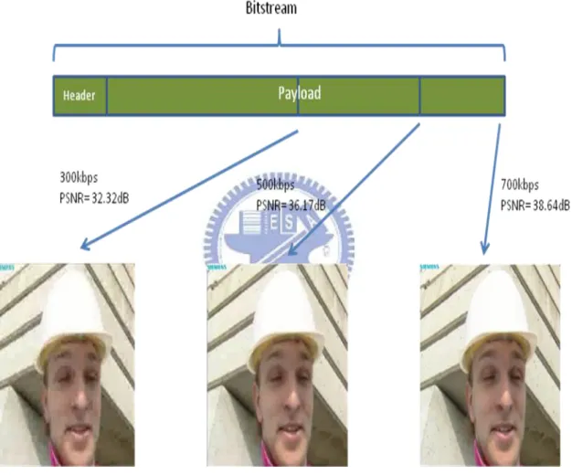
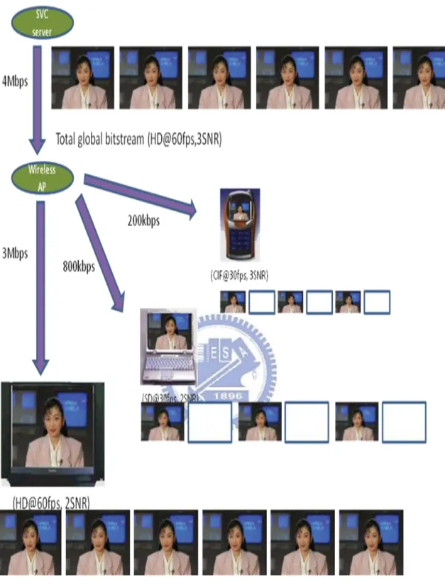
The SVC makes it possible that the various networks, either in wireless or cable, streaming applications such as Personal Computer (PC), high definition TV (HDTV) and even mobile devices can display the same video with different specification according to each device‟s own requirements from one scalable global bitstream. As the illustrated application scenario for SVC shown in Figure 2-1, the system consists of a SVC server which contains the SVC encoder, a wireless access point (AP) which may includes the SVC extractor and the wireless transmission mechanism and three clients connect to the network with different communication conditions. The SVC server delivers the global bitstream to the wireless AP without any truncation while the connection is usually in cable. The wireless AP extracts the different required resolutions for recipients in the heterogeneity network.
Figure 2-1 SVC overview
2.1 Encoder Overview
In Figure2-2 we introduce a generic encoder structure overview of SVC with three spatial layers which encodes the video into multiple spatial, temporal and
quality (SNR) layers for combined scalabilities [1] [2]. The encoding is a layer-based approach that separate the input video into several spatial layer first in order to support multiple spatial resolutions and then coded with separated encode loops. For each spatial layer, the temporal scalability is achieved by using hierarchical-B structure, a temporal decomposition. Since the predict information comes from either spatially lowed layers or temporally neighboring pictures at the same spatial layer, the inter-prediction scheme can exploit the correlations among the layers and reuse the information to improve the coding efficiency of the enhancement layers [1]. After the inter-layer prediction module, the residues of each spatial layer are encoded with either scalable entropy coder for fine grain scalability (FGS) or non-scalable entropy coder for coarse grain scalability (CGS) to support SNR scalability. However, there is a restriction that the first SNR layer (also called base layer) in each spatial layer need to be encoded with non-scalable mode.
2.2 Temporal Scalability
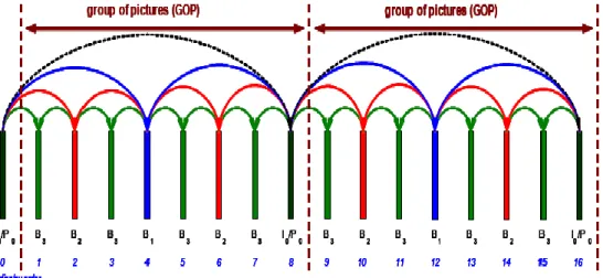
Figure 2-3 Hierarchical-B prediction structure with GOP size of 8
The temporal scalability in SVC which allows of supporting multiple frame rates is implemented by using hierarchical-B prediction structure. Figure 2-3 gives an example of hierarchical-B structure with GOP size of eight that supports four temporal layers. The pictures of lower temporal layer are encoded first such that the higher temporal layer can refer to the lower layer‟s pictures.
Frame 0, 8 and 16 in Figure 2-3 are called key frames. Each key frame is either a I-frame which contains the prediction information itself or a p-frame that using only the previous key frames as reference for the inter prediction. Each GOP can be independently decoded if the preceding key frames are available. The other frames between two key frames are B-frames. Each B-frame is hierarchically predicted by using both previous and future frames from lower temporal layer as reference pictures.
2.3 Spatial Scalability
The spatial scalability is achieved by dissolution the video into spatial pyramid which the video is down-sampled to generate different spatial resolutions. The different layers are independently coded. In order to improve the coding efficiency of enhancement layer, inter-layer prediction is introduced (and the inter-layer prediction scheme is used in intra-texture, motion and residue prediction).
The inter-layer prediction is assembled according to the types of layers used. The base and the CGS layer can select the reference layer from any lower layers flexibly while the FGS layer must predict from the previous SNR layer at the same spatial layer. In Figure 2-4 shows an example of inter-layer prediction with three spatial layers and each spatial layer contains several SNR layers which may be either CGS or FGS while the base layer of spatial layer must be CGS. The notation X_Y_Z used in the picture, for example CGS_1_0, specified each SNR layer in each spatial layer and used for decoder to identify the layers. The symbol X denotes the coding method including BASE, CGS and FGS. The Y indicates the dependency_id which increase one while access successive spatial layers or CGS layers such as from CGS_1_0 to CGS_2_0. The third symbol Z designates the quality_id which is incremented by one for successive FGS layers.
In spatial layer 0 of Figure 2-4, BASE_0_0 that is agreeing with H.264/AVC is the base layer of spatial layer 0. Above BASE_0_0, there are two other SNR layers encoded with CGS mode in spatial layer 0, CGS_1_0 and CGS_2_0 which are predicted from BASE_0_0 and CGS_1_0 respectively. Because SVC supports flexible selection of reference layer, the base layer of spatial layer 1, BASE_1_0, and the upper SNR layer CGS_4_0 are refer to the CGS_1_0 and CGS_2_0 instead of CGS_2_0 and BASE_4_0 individually. So, the CGS_4_0 can be decoded even when the BASE_4_0 doesn‟t receive correctly, for example. These flexibility leaves room for further optimization.
The FGS layers can only refer to the previous layer that is different to the rules of CGS layer, such that FGS_4_1 refers to CGS_4_0 and FGS_4_1 itself is the reference picture of FGS_4_2 and go on. According this rule, if we encoded every enhancement layer as FGS, the base layers are all necessary while decoding the above enhancement layers.
Figure 2-5 shows an example of adopting the spatial scalability with three levels and in each spatial layer still has SNR layers to further improve the quality.
Figure 2-4 Inter-layer prediction structure with three spatial layers [2]
2.4 SNR Scalability
SNR scalability uses multiple SNR layers in each spatial layer to provide the scalability of quality. Figure 2-6 shows an example that the more SNR layers been decoded correctly, the higher quality the picture can achieve.
SNR scalability can be achieved via Coarse Grain Scalability (CGS) and Fine Grain Scalability (FGS). CGS encodes in a non-scalable way while FGS can be truncated at any arbitrary position.
Figure 2-6 Illustration of SNR scalability
2.4.1
Coarse Grain Scalability (CGS)
The CGS data can only be decoded at several pre-defined integral points as shown in Figure 2-7(a). CGS seems like an additional spatial layer with smaller quantization parameter (QP). The only difference between CGS and a spatial layer is the inter-layer prediction of CGS reuses the information from lower layer without spatial interpolation, treat as every layer have the same resolution. Such that CGS doesn‟t use motion vector refinement as in spatial scalability [2].
2.4.2
Fine Grain Scalability (FGS)
FGS can allows truncation at any arbitrary location that FGS provide arbitrary quality levels according to the user‟s bandwidth capability which may be fluctuant as shown in Figure 2-7(b).
By scanning the whole frame, each FGS enhancement layer can provide a refinement of the residue signal, Such that the quality improvement can be separated in the entire frame. There are many successive improvements of FGS and more details of FGS are introduced in [2].
Figure 2-7 SNR scalability (a)CGS (b)FGS
2.5 Bit stream Extraction
An extractor is used to extract the single SVC bit stream which is consisted of a set of spatial, temporal and quality resolutions to reach the informed bit rate that is fluctuated by the bandwidth available. There are two extraction methods named simple truncation and quality layer adaption [1].
2.5.1
Simple Truncation
The extractor must determine all the reference pictures that are required to decode the base layers for the target spatial-temporal resolutions. Then extract from the lower layer to the higher layer due to the causality in encoding. If only partial
layers are allowed to transmit due to the available bandwidth, the higher layers would be truncated earlier while more bandwidth available, the more quality layer of the requested spatial-temporal resolution can be transmitted.
The extractor can only truncate the bit stream at the layer boundary if CGS scheme is used in the SNR scalability while if FGS scheme is adopted, every picture is equally truncated according to the informed bit rate.
2.5.2
Quality Layer Adaption
For quality layer adaption, the extractor adds a control information named quality_layer_id in the Network Abstraction Layer (NAL) unit. It is consisted in FGS layers to indicate the importance of the NAL unit and provide better bitstream adaption. The less important one would be dropped earlier.
The extractor, similar in the simple truncation, keeps the dependent quality layers in the order from lower layer to higher layer to reach the target bitrate. The extractor compute the bitrate of each quality layer and remove the NAL units in quality layers according to the quality_layer_id. If the bandwidth is not enough to transmit all the NAL units in the quality layer, the NAL units with the same quality_layer_id would be truncated equally.
CHAPTER 3
BRIEF OVERVIEW OF WIMEDIA UWB
This chapter briefly introduces the structure and characteristic of the WiMedia.
Ultra wideband (UWB) is the wireless networking technology of the next generation with the features of extremely high data rate which can be up to 480Mb/s with in the distance up to 10m、low interference with other radio system and low power consumption. The advantages of UWB bring many benefits to users and make several new applications. One of it is the idea of E-HOME, which wants to use the UWB technology to connect the consumer electronics in house.
WiMedia is the UWB-based specification which has more than 170 companies to participate in including Intel, Texas Instrument, SONY, Nokia, Microsoft, etc [4] and due to the high data rate in short range with the low transmission power, WiMedia also enables the high speed wireless personal area networks (WPANs). WiMedia use the MultiBand Orthogonal Frequency Division Multiplexing (MB-OFDM) [5], splits a signal into fourteen 500 MHz-wide bands shown in Figure 3-1 and uses OFDM to increase bandwidth, proposed by MultiBand OFDM Alliance (MBOA) [5] as its PHY technology. The MBOA merged with the WiMedia Alliance [6] to promote and standardize the UWB on March 2005 and renamed the original MBOA-UWB to WiMedia UWB. On December 2005, the European Computer Manufacturers Association (ECMA) adopted the WiMedia UWB as its standard and completed high rate Ultra WideBand PHY and MAC standard -ECMA-368 [7]. We choose the standard ECMA-368 which is equal to the WiMedia UWB as our simulation system.
3.1 Brief Introduction of WiMedia UWB MAC
The characteristics of the WiMedia MAC protocol include to preserve the frame structure (including super-frame and the MAC header ) which is specified by IEEE 802.15.3 task group [8]、TDMA liked structure、adopt the CSMA and the RTS/CTS mechanism similar as the enhanced distributed channel access (EDCA) [9] mechanism of WLAN standard、 two distinguish features namely beaconing and distributed reservation protocol (DRP) which let the fully distributed coordinate architecture without the Piconet Coordinator (PNC) to control the medium access and because of these, the MAC functionality is individual for each device in the networks.
3.1.1
Super-frame Structure
The WiMedia MAC layer divides the transmission time into consecutive super-frames. Super-frame is a period of time interval used in the standard for coordinating frame transmission between devices.
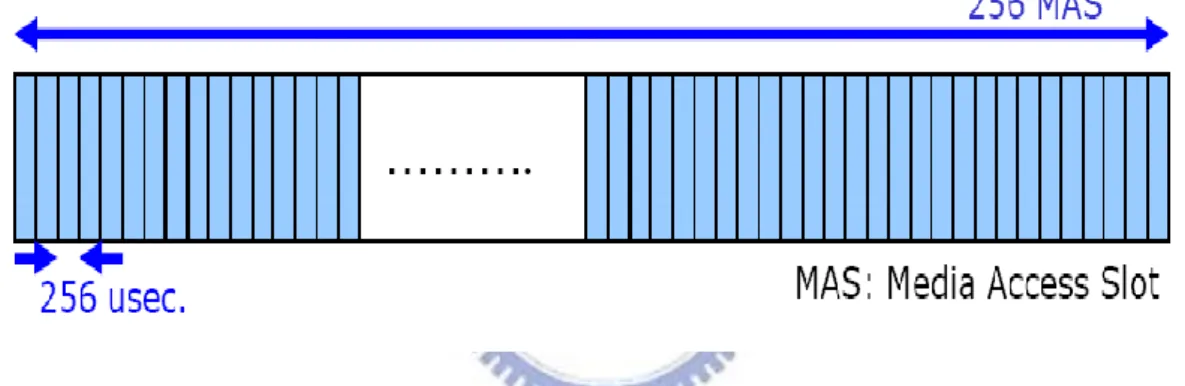
Figure 3-2 Super-frame structure consist of media access slot
Figure 3-2 shows the time structure of super-frame of WiMedia MAC layer, which is composed of 256 Media Access Slot (MAS) and the interval of each MAS is 256 usec. So the total duration of a super-frame is 256*256 = 65,536 usec.
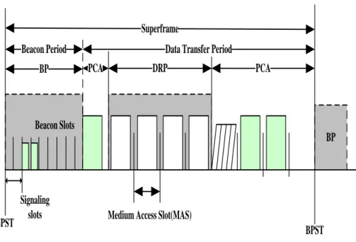
The super-frame is separated into two parts, Beacon Period (BP) and Data Transfer Period (DTP), according to the functionality. According to the media access methods, the Data Transfer Period can be divided into Distributed Reservation Period (DRP) and Prioritized Contention Access (PCA) as shown in Figure 3-3.
BP DRP
Superframe
Beacon Period Data Transfer Period
PCA PCA
BPST Medium Access Slot(MAS)
BPST BP
Beacon Slots
Signaling slots
Figure 3-3 Structure of super-frame of WiMedia MAC
3.1.2
Frame Transaction
A source device may fragment or aggregate MSDUs into several frames and transmit frames with the same Delivery ID and address to the same destination address [10]. A frame may be considered received by the device if it has a valid Header Check Sequence (HCS) that protect the combination of the MAC layer header and the PHY layer header and Frame Check Sequence (FCS) that contains 32-bits which represents CRC, used to check the correctness of the frame in the receiver.
Before any frame transaction, the transmitter has to send a Request To Send (RTS) and waiting a period of Short Inter-Frame Space (SIFS) that every single frame transmission shall be separated by a SIFS interval. After that it expects to receive a Clear To Send (CTS) from the receiver as shown in Figure 3-4. RTS/CTS is also the mechanism used by IEEE 802.11 wireless networking protocol to reduce the collisions introduced by the hidden node problems. If the transmitter does receive the CTS, it begins the transmission. Otherwise, the transmission fails and the transmitter release the rights to access medium.
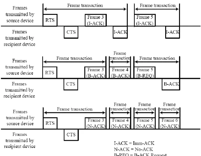
There are three acknowledgement policies in frame transaction to verify the delivery of the frame which are Imm-ACK、B-ACK and No-ACK. In No-ACK, the receiver doesn‟t acknowledge the transmission and the transmitter treats it as successfully without regard the actual result. In Imm-ACK, the receiver acknowledges a Imm-ACK frame after a correct frame-reception. And B-ACK allows the transmitter to transmit multiple frames while the receiver keep trace the reception until the block
terminate and receive a single frame from the receiver to indicate which frames were received and which frames need to be retransmitted [11].
Figure 3-4 illustration of frame transaction
3.1.3
Overview of Beacon Period
The beacon mechanism is the most fundamental and very important in the operation of WiMedia MAC.
In WiMedia, each super-frame starts with BP extends one or more continuous MASs which is up to 32 MASs for Beacon transmission and the first MAS start in the BP, in the super-frame, is called Beacon Period Start Time (BPST). For each MAS in BP are allowed to transmit beacons but no data transmission and it can transmit three beacons in the three beacon slots in a MAS, which means the total BP can transmit 3*32 beacons at most. Beacons are used for announcing presence, coordinate with neighbors, topology control and negotiate traffic in the medium. Because there is no central coordinator, beacons play a key role to let the system completely distributed coordinate instead of central.
In original, the IEEE 802.15.3 MAC need a PNC as a central controller and any device whether portable or not can be the PNC. Communications between devices can only enable or through by the PNC. Without PNC, the WPAN can‟t operate any more. For example, if the PNC disappears either due to the mobility or the device failure, there needs several seconds to elect a new PNC to control the networking and all the communications can‟t be maintained during the reorganization [4]. That‟s why the WiMedia MAC adopted distributed architecture which let the functionality of negotiate resource allocation on each device instead of the PNC.
Without the central information from PNC, each active device in the network needs to discover the WPAN information by itself and update periodically to make the correct decision. This is done by the transmission of management and control information which coded as Information Element (IE) of different functionalities in beacons. Beacon frames should transmit at the lowest rate 39.4Mb/s to enhance the robustness to avoid the missing of the most important information within the system.
According the WiMedia MAC standard, each device has to announce its existence by sending a beacon frame in the BP in order. Each beacon contains the device ID of its originating device and IDs of all its direct neighbors whose beacons had been heard by the device in the previous super-frame to exchange the existence and the topology information nearly heard to each other.
After scanning the neighbors‟ beacons, devices may know the nearby network information and which MASs are available while others are in used. For example, device A wants to transmit data to device B by DRP mechanism within MASs #140~145、device C wants to transmit data to device D through PCA mechanism to
content with others in MASs#161~165 etc, these are coded in the beacons. To collect the information carried by beacons let the devices know how to transmit data or response others requirements.
3.1.3.1 Beacon Group
Devices may transmit their own BPST and BP length in the BP. BPST is used mainly for synchronization of devices in the network and the BP length is used to indicate the number of beacon slot been occupied which also shows the number of devices within range, the maximum of BP length can‟t exceed mMaxBPLength = 96. Devices communicate with others should listen for the beacons during the BP length it announced in the last super-frame.
A beacon group is defined as a set of devices who are one-hop away the device and have the same BPST, which means the beacon group may be different from device to device. The extended beacon group is the union of a device‟s beacon group and all the beacon groups in the device‟s beacon group as shown in Figure 3-6.
If a device does not receive a beacon from another device for more than 3 consecutive super-frames, it will not consider the device is no longer in the network.
3.1.3.2 Beacon Transmission And Reception
Before transmit any non-beacon frame, a device should scan for beacons on the chosen channel for at least one super-frame, if it can‟t hear any beacon from its neighbor, it will create a new BP and send its beacon in the first beacon slot right after the signaling slots. Otherwise it will use the same BP as the neighbors and transmit its beacon in a beacon slot randomly selected from up to 8 beacon slots after the last unavailable beacon slot but not exceed the end of the BP. If there is no available beacon slot in BP, a device should use the signaling slot to extend the existing BP by randomly select a signaling slot and setting the slot bit to one. Once a device received a beacon in its signaling slot in the previous super-frame, it should enlarge its BP length to include the beacon slot which is occupied by the beacon in the signaling slot. Then the device will update the BP occupancy IE (BPOIE), one of the most important IE. The BPOIE contains a list of devices in the beacon group. The flow is illustrated in Figure 3-7.
Figure 3-7 Flow of network entry
3.1.3.3 Beacon Collisions Detection
BPOIE is used to update the BP length and detect the beacon collisions, which may occur when two or more devices in two-hop range send beacons at the same beacon slot mostly due to the mobility of devices who have different BPST. To avoid beacon collision, the devices within the range of two-hop of a device need to
send beacons in different beacon slots and devices out of two-hop of the device can use the same beacon slot. This enables the spatial reuse of the beacon slots. Once a beacon slot is selected, the device always uses the beacon slot to transmit beacon unless beacon collision happens.
3.1.3.4 Synchronization
Because the WiMedia MAC is TDMA-liked structure and the device derives all the time measurements for communication with its neighbors according to the BPST, it has to synchronize the clock with other devices in its own beacon group.
When a device receives a frame from its neighbor it should calculate the difference between the actual reception time and the expected reception time by the formulate Difference = Actual reception time – Expected reception time. The actual reception time is the estimation of time from the start on receiving the preamble and the expected reception time is determined from the Beacon Slot Number field of the arrived beacon and the receiving device‟s BPST. The receiving device should adjust its BPST in order to maintain super-frames synchronization with its lowest neighbor. If the difference is positive, the neighbor is considered slow and the receiving device would delay its BPST by the difference.
3.1.4
Overview of Prioritized Channel Access (PCA)
The PCA protocol is similar to the EDCA mechanism specified in the IEEE 802.11e standard. With different priorities for the four kinds of access categories (ACs) -video、voice、background and best effort-defined by the upper layer, PCA provide differentiated and distributed inter-frame space (IFS) for ACs to obtain a TXOP to transmit its frames. Each AC has a frame buffer in the device for transmission and the AC will employ the contention procedures if the buffers are not empty while the MAS is available for PCA.
As shown in Figure 3-8, each AC has its own Arbitration Inter Frame Space (AIFS[AC]), which indicates the priority of ACs and defined as
time slot AC AIFSN SIFS AC
AIFS[ ] [ ]* _ . A device has to wait channel to be idle for duration of AIFS[AC] before decreasing the backoff counter in order to prevent the collision with other devices‟ accessing channel.
Figure 3-8 IFS relations for PCA Table 3-1 parameters of ACs
AC_VO AC_VI AC_BK AC_BO
mCWMIN[AC] 3
7
15
15
mCWMax[AC]
255
511
1023
1023
mAIFSN[AC]
1
2
4
7
Backoff counter is a randomly selected integer from [ 0 , CW[AC] ], CW[AC] is contention window and also randomly chosen from the range of [ mCWmin , mCWmax ] [10].
The device shall determine which AC gets the opportunity to send frames if buffer not empty by checking AIFS[AC] + backoff counter[AC] and the priority internally first as shown in Figure 3-9. In turn,each AC independently perform the contention for right with different parameters to send frames by following the rules. And take the smallest AC as the device„s actual AIFS and backoff counter to content with other devices.
Figure 3-9 Internal contention of ACs
If a device‟s backoff counter reaches 0 means it gets the TXOP which notes has the right to transmit if the channel is actually idle and the device should send as many frames as possible until the remaining time of TXOP is not enough. Others may pause the backoff counters to wait the next time for employing the PCA process. If a device‟s backoff counter reaches 0 but the channel is not idle yet, it should increase its CW[AC] and choose another backoff counter to start the backoff process later while the medium is idle again.
The PCA protocol is similar to the EDCA mechanism of WLAN, and the difference between them is in the use of UWB-PHY. In IEEE 802.11 a/b/g, the carrier sensing mechanism is base on detecting the increase of energy level in the wireless medium which can indicate there may be frame transmission in the medium. But in WiMedia, because of the signals‟ low power characteristic,sometimes the power of signals even below noise level, the carrier sensing mechanism in PCA of WiMedia can‟t base on energy detection but has to use the preamble sensing which can also be called Preamble Sensing Multiple Access (PSMA) rather than CSMA. This means the medium is considered busy if a WiMedia frame preamble is received. The difference described above makes PCA sometimes less efficient than EDCA because it has to wait longer while checking if the medium is really idle.
3.1.5
Overview of Distributed Reservation Protocol (DRP)
DRP, one of the important features of WiMedia, is the protocol implemented in devices used to negotiate and pre-reserve the time to access channel with their communication peers which may be one in uni-cast or more in multi-cast.
While PCA can‟t provide any guarantee for the real time service, but in DRP, the device reserves a period of time for transmission during which the reservation owner has the exclusive access to the medium. A device can only reserve the MASs those are not in used by other existing reservations and the resources wants to reserved must be available both in the transmitter and receiver beacon groups.
There are two mechanisms to negotiate the DRP reservation. One is explicit, which uses DRP Reservation Request/Response to negotiate and the other is implicit, which negotiate in the form of DRP IE in the beacon frames. The reservation negotiate initial with the transmitter, the reservation owner, send the reservation request to the receiver, the reservation target. After receiving the request, the receiver analyze the resources utilization of its beacon group and response that if the request is grant or not.
The process of negotiate has some basic rules to obey [11]:
1. “Alien BP Reservation” has the highest priority, which hopes to avoid the collisions with the alien beacon group.
2. the reservation owner set the Reservation status bit in the DRP IE to one after receiving the DRP IE from the reservation target with Reservation status bit to one, which means grant the reservation.
3. if the reservation is not granted, the reservation target should provide more information about the resource such as DRP available IE in the beacon to the reservation owner to find the appreciate MASs to transmit.
4. if more than two devices are under reservation, the device with the lower beacon slot number gets the higher priority if the Tie-breaker bit is the same.
The DRP_available_IE is used to provide information of the available MASs for transmission. If a MAS has been reserved or occupied by alien BPs, the corresponding bit of the MAS shall be set to one. The simplified flow of DRP negotiate has been illustrated in Figure 3-10.
Please reference to the ECMA-368 standard to get more detail about the reservation process and rules.
Figure 3-10 Flow of DRP negotiate
There are five types of reservation-Hard Reservation、Soft Reservation、 Alien BP reservation、Private Reservation and PCA Reservation.
In Hard Reservation, no other transmission is allowed in the period and all the transmission have to terminate for at least pSIFS plus mGuardTime(12us) before the reservation process in order to let the reservation owner can start its reservation at the beginning of the reserved MASs without any initialized procedure. If after the reservation owner has completed the transmission of the associated frames but there is still remaining time in the reservation period, the reservation owner can release the remaining time by broadcasting Unused DRP reservation Announcement (UDA) and the devices received UDA should response Unused DRP reservation Response (UDR). If the remaining time can‟t stand for the exchange of UDA and UDR, the release process won‟t start.
In soft Reservation, all the devices content for the medium access with PCA mechanism but the reservation owner has the highest priority to access the reservation MASs without any backoff. If the reservation owner has leaved unused time slot in the period, those are open for contention under PCA mechanism by the neighbors of the device.
Table 3-2 The rest DRP reservation types
Reservation
Type
Description
Alien BP
Prevents transmission during MASs occupied by an alien BP Has the highest priority among all types of reservations
Private
Reserved for special purpose and acts like hard reservationPCA
All devices may access the medium by PCA mechanismwithout preferential access.
3.2 Brief Introduction of WiMedia UWB PHY
Ultra wideband which was historically considered as impulse radio technology, transmit with short duration pulse, has been used mostly by military applications such as radar, etc. However, due to the hardware and RF technology are improved impressively, the Federal Communications Commission (FCC) approved the UWB technology for more commercial application by open up the frequency spectrum in the 3.1-10.6 GHz band for unlicensed UWB applications with extremely low power limits at -41.3dBm/MHz, which makes UWB be possible to co-exist with other radio systems without the interferences and the available spectrum becomes more efficient, on April 2002. Now, a device can be considered as an UWB device if its -10dB bandwidth is greater than 500MHz according to the FCC‟s definition.
In order to provide the data rate of WPAN that in some applications may as high as 500 Mb/s and obey the power limit specified by FCC, the PHY layer need to get as large bandwidth as he can to achieve such high data rate. But, it also increases the system cost and complexity for increasing the bandwidth. WiMedia PHY had proposed a OFDM system which separates the frequency spectrum into 14 subbands each subband gets bandwidth of 528MHz and one OFDM symbol is transmit in a subband. The 14 subbands are grouped into four band groups of three subbands each and one band group of two subbands. In addition to provide wider system bandwidth, WiMedia enables to transmit simultaneously by different band groups.
The WiMedia PHY standard provide data rates of 53.3、80、106.7、160、200、 320、400 and 480 Mb/s. The channel bit rate is 640 Mb/s and the data rate equals the channel bit rate multiply the coding rate with divided with two if using the spreading either frequency-domain or time-domain. Take 80Mb/s as example, its coding rate is
1/2 while it uses both frequency-domain spreading and time-domain-domain spreading which means it may be divided with 2 twice. So
s Mb s Mb / 80 2 * 2 ) 2 / 1 ( * / 640
Table 3-3 Data rate and coding modulation supported by MB-OFDM Data Rate (Mb/s) Modulation Coding Rate Frequency-Domain Spreading (FDS) Time-Domain Spreading (TDS) 53.3 QPSK 1/3 YES YES 80 QPSK 1/2 YES YES 106.7 QPSK 1/3 NO YES 160 QPSK 1/2 NO YES 200 QPSK 5/8 NO YES 320 DCM 1/2 NO NO 400 DCM 5/8 NO NO 480 DCM 3/4 NO NO
Table 3-4 WiMedia MAC timing parameters Parameter Value Description mGuardTime 12us Guard Time mMasLength 256us MAS Period
mMaxFragmentCount 8 Maximum Fragment number pSIFS 10us SIFS Time
CHAPTER 4
THE FEEDBACK SCHEME OF WIMEDIA
MAC FOR H.264/AVC SVC STREAMING
In this section, we will introduce the proposed feedback scheme that makes use of the combination of WiMedia and SVC‟s properties in order to decrease the chance of video latency which is sometimes the major issue discomfort users.
4.1 Purpose of Feedback Scheme
As stated, SVC can provide spatial, temporal, and quality scalabilities by the extraction process that truncates the entire single bitstream to multiple spatial, temporal, and quality resolutions by the extractor. Although extractor is capable of providing partial bitstreams to meet the specific target bitrate with many improved scheme [12], the issue is feedback control of the extractor based on actual available bandwidth.
Due to the fully distributed architecture of WiMedia and various wireless environments, the available bandwidth for SVC real time streaming service fluctuates. In order to effectively provide QoS of the real time streaming service in WiMedia system, a proper feedback control to decide the transmission bitrate for SVC extractor is critical.
4.2 The Effects of Feedback Scheme
The available bandwidth may vary frequently because of the wireless channel condition and the reservations negotiated between devices. But the SVC extractor changes the target multimedia bitrate only at the beginning of each group of pictures (GOP). During the period of GOP, the transmitted multimedia bitrate which is informed by the WiMedia MAC remains the same.
The difference between available bandwidth and the transmitted multimedia bitrate, reported back by the WiMedia MAC to the extractor, may result in bandwidth waste at the transmitter or the video latency at the receiver. If the available bandwidth is less than the transmitted multimedia bitrate which extracted by the extractor for a period time, it may be highly possible that the decoderbuffer, used to store the multimedia data at the receiver for the decoder to decode, would be whether in the
underflow stage or even in the null stage which means there is no multimedia data in the decoder buffer and would cause the video latency at the receiver. On the contrary, if the available bandwidth is greater than the transmitted multimedia bitrate, partial bandwidth seems like wasted. Because the total bandwidth resource is shared by all the devices with other services and would be limited for the SVC real time streaming service to obtain, the bandwidth resource utilization is thought need to be more efficient. Either the probability of video latency or the utilization decrease of the available bandwidth may be caused if the transmitted multimedia rate reported back by the feedback scheme is distant from the actual available bandwidth for a period of time.
4.3 System Architecture
There have been several discussions about the transmission of SVC streaming with network adaptation in [13] [14] [15]. In the transmitter, we design and propose the MAC layer contains MACbuffer, transmit mechanism, SNR monitor and extraction decision engine, while the SVC layer consists of SVC encoder and SVC extractor.
The SNR monitor is response to detect the wireless network condition. The transmit mechanism represents the other functionalities of MAC layer including reservation negotiations, fragmentation, etc. The MACbuffer receives and stores the extracted bitstream to be transmitted from SVC extractor. The MACbuffer is divided into two parts and adopts first in first out (FIFO) mechanism which means if there are residue data in MACbuffer#1 due to the lack of bandwidth while the following bitstream has successively arrived MACbuffer#2, the transmit mechanism will deal with the residue in MACbuffer#1 before those in MACbuffer#2. The division of MACbuffer is supported for the content-based adaption, in order to monitor the residual data in MACbuffer with different extraction bitrate and will present more detailed in section 4.4.2.2.
The extraction decision engine calculates the preferred extraction multimedia bitrate for the SVC extractor in order to achieve better QoS according to the informed information of reservation results, the monitored SNR, and the fullness of MACbuffer.
Over the network, the extracted SVC bitstream will be transmitted to the receiver which consists of SVC decoder and YUV player for playing as shown in Figure 4-1, a diagram of system structure of transmission.
Figure 4-1 System architecture of transmission
4.4 Proposed Feedback Scheme
We treat video latency which discomfort users mainly as the urgent and most important issue to be solved. Some aspects of the approach of SVC hope to decrease the same problem by the scalabilities.
In the thesis, we consider there should be two steps, estimation and adaptation, to calculate the appreciated extraction bitrate for the extractor in the extraction decision engine and we proposed a mechanism contains both. We observe the information of the past period of time in advance. Then estimate the probable situation of following period of time in order to fit the actual available bandwidth
more precisely. At the second step, we take advantage of the SVC scalability to further reduce the chance of video latency while hope to maintain the utilization of bandwidth in a reasonable region.
4.4.1
Estimation
As other methods, we assume the average bandwidth of the next GOP period, the time interval we report the extraction bitrate to the SVC extractor, will not deviate from the last GOP period too much. Therefore enable us to use the information which we can get from the past to predict the followings. Because the bandwidth is affected by the number of available MASs in reservation and SNR which will not change greatly while in the static environment such as in house. We estimate the number of available MASs, the available time for transmission, in advance. As introduced in chapter 3, the Data Transmit Period (DTP) contains not less than 224 MASs and we assume the worst case that total MAS can be reserved is 224 MASs. We estimate the number of available MASs through estimate how many percentage of total MAS are available.
Calculate the standard deviation σ of y1~yn, the available MASs of the n
super-frames in the past GOP period, by (1) and use it to find out the average standard deviation σ ‟ of the next GOP period according to (2).
)
1
(
)
...(
)
(
)
(
1 2 1 2 2 2 1 2
n
y
y
y
y
y
y
n n n n
(1) n n n n ) 6 ) 1 2 ( ) 1 ( ( ' (2)With the standard deviation σ ‟, we can determine the distribution Z, as in (3), of the average percentage of available MASs for each super-frame in the next GOP period.
)
)
(
,
(
~
N
' 2Z
(3)After estimating the distribution Z of the average of available MASs, we can calculate the expectation value (E_MAS) that has the most chance to occur in the next GOP period, by multiply each value with their probability density.
Because Z can be from
to
, we define
<Z<0 is represented of available percentage 0% and probability density isP0. 0 <Z<1 is represented of available percentage 1% and probability density isP1.99 <Z<
is represented of available percentage100% and probability density isP100. The formula for expectation value (E_MAS) is listed below:
100 0 ) * ( _ z z P z MAS E (4)Use the E_MAS to be the available MASs in the next GOP period and consider the mechanism of frame transaction and the fragmentation, we can find out how much time can use to transmit data. After knowing the available transmission time, by multiplying the modulation rate shown in Table 3-3 which is affected by the SNR, we can get the bandwidth for transmission in each super-frame in the next GOP period.
BW = Available_Time*Modulation_Rate (5)
4.4.2
Adaptation
The performance of the proposed estimation method is better than the compared methods as shown in Figure 5-2, but it is thought can be further improved.
Besides proper estimation, dynamical adjustment of the estimation which takes the video latency issue into consideration can efficiently handle the bandwidth fluctuations which may cause the video latency.
4.4.2.1 Relationship between MACbuffer and Decoderbuffer
In our performance analysis, we observed the variation of the fullness of decoderbuffer by inspecting the fullness of MACbuffer successively. As shown in Figure 4-1, we store the multimedia bitstream after the extraction process from SVC extractor in the MACbuffer and wait to be transmitted. Similarly, the decoder needs a decoderbuffert to store the received multimedia data for replay at the receiver.
We can adapt our estimation according to the fullness of MACbuffer because the fullness of MACbuffer can indicate the level of miss-estimation which also affects the fluctuation of fullness of decorderbuffer. If there are over-estimations for a period
of time as shown in Figure 4-4, the fullness of MACbuffer increase and the fullness of decoderbuffer decrease.
Figure 4-2 Relation between MACbuffer and decoderbuffer
4.4.2.2 Content-Based Adaptation
In order to help to reduce the chance of video latency, we take advantages of the scalabilities of SVC to propose an adaptation mechanism.
The adaptation mechanism modifies the estimation bitrate from step1 according on the fullness of MACbuffer dynamically. The modified size is shown in (6). erframe erframe MACbuffer Modify
T
N
Data
Rate
sup sup*
*
(6)RateModify : the modified size of estimation bitrate (kb/s)
α : indicates the adjust ratio of the modified size and 0≦α ≦1 DataMACbuffer : the remaining data in the MACbuffer (kb)
Nsuperframe : the number of super-frames in a GOP period
After obtaining the adjustment, the extraction decision engine will adjust the estimation bitrate according to (7) and send the modified transmission bitrate back to the SVC extractor for extraction.
Rate
Report= Rate
Estimation– Rate
Modify (7)RateEstimation : the estimation bitrate from step1 (kb/s)
RateModify : the modified size (kb/s)
RateReport : the modified transmission bitrate which is reported back to the extractor
(kb/s)
Adjust the extraction multimedia bitrate by reference to the fullness of MACbuffer can efficiently reduce the chance of video latency when there comes up successively miss-estimations. If the fullness of MACbuffer gets much, it may note that the estimations are too high to fit the available bandwidth, so the adaptation will decrease the estimations more. On the contrary, if the fullness of MACbuffer is few, the adaptation will decrease little which may stay the quality of pictures. Figure 4-3 shows the flow of content-based adaptation
Figure 4-3 Flow of content-based adaptation
4.4.2.3 Improved Observation
Figure 4-4 and Figure 4-5 illustrate an example of the improvement of applying the content-based adaptation. After a period of miss-estimation, the conventional estimation method in Figure 4-4 leaded to the happening of video latency in the 8th super-frame. However with the content-based adaptation in Figure 4-5, the extraction decision engine will modify the estimation bitrate and report the modified bitrate, Report rate, back to the extractor. As shown in Figure 4-5, the content-based adaptation reducedthe happening of underflow in the decoderbuffer in the 8th super-frame.
CHAPTER 5
SIMULATION RESULT
5.1 Simulation Setup
5.1.1
SNR Generation Model
The working environment of WPAN may be indoor residential and commercial buildings and in [16] had shown the time-invariant characteristic of this kind indoor UWB channel. As introduced in [17], it measured the time snapshot of the channel at each spatial point over 20 commercial building and 20 residences to build database. In each building, it performed 25 measurements on a grid around 30 locations with transmitter-receiver separating from 0.8m to 10.5m for both line-of-sight (LOS) and non-line-of-sight (NLS) as illustrated in Figure 5-1.
Figure 5-1 Illustration of the spatial measurement in a typical building [17] It invested the path loss model described below by data regression and proved the result of model is similar to the measured data through simulations. Because the model is regressed from the experimented database, it has included the effect of multipath and the shadowing effect but without mobility. The path loss model fixed
0
PL at the mean taken over all buildings while , , and indicate the mean and standard deviation of independent Gaussian distribution and respectively. The parameters of path loss model are different among building environments and listed in Table 5-1 Parameters of path loss model.
10 1 10 2 010
log
(
)
10
log
(
)
)
(
d
PL
d
x
d
y
yx
PL
r
r
(8)Average Path Loss : PL0 10rlog10(d)
Deviation from Average Path Loss : 10rx1log10(d) y yx2
The deviation from the average path loss is affected by the combination of the zero-mean, unit variance Gaussian random variables x1, x2 and y. The part of
yx2
y is usually referred as the shadowing [17].
Table 5-1 Parameters of path loss model
Environment
LOS Commercial 43.7 2.04 0.30 1.2 0.6
NLS Commercial 47.3 2.94 0.61 2.4 1.3
LOS Residential 47.2 1.82 0.39 1.5 0.6
NLS Residential 50.4 3.34 0.73 2.6 0.9 Applying the parameters which are listed below and referred from [18] into the formulation SNR = Pt – PL - noise, we can obtain the value of SNR.
Parameter Value Distance 10ft
Average transmit power -9.5dBm
Average effective noise power -81.2dBm
5.1.2
Available MASs Generation Model
We perform the simulations with two kinds of distribution of the available MASs in reservation to confirm if the proposed scheme works in other distribution.
5.1.2.1 Normal Distribution
Generate a Gaussian random variable with a set of pre-determined mean and variance repeatedly while keeping the mean and the variance fixed during the
0
simulation. The Gaussian random variables Gi represent the percentage of available
MASs and N indicates the total available MASs for the ith super-frame.
(9)
5.1.2.2 Poisson Distribution
Select a number as the mean in advance to build the Poisson distribution and choose a random number Pi as the percentage of available MASs of the ith super-frame successively.
(10)
5.1.3
Fragment Model
After WiMedia MAC was informed the information of SNR and negotiated reservation, the extraction decision engine is required to calculate how many bandwidth is available in each super-frame. Due to the overheads in WiMedia are heavy, the reserved MASs are not totally for transmission. We first check the DRP_available_IE to see how is the MASs‟ separation in the super-frame. Within each successively MASs, by adopting the I-mm-ACK policy as shown in Figure 3-5, take the overheads into consideration to calculate how many frames and the frame-length can be transmitted in the super-frame with the transmission rate provided by the modulation.
5.2 Simulation Results
In the performance analysis, we first check the performance of the proposed estimation. Then combined the content-based adaptation on the proposed estimation as our proposed scheme and compared with two other methods, Infinite Impulse Response (I.I.R) and least square method in three aspects, the probability of the decoderbuffer falling into null stage, the required size of MACbuffer, and the average percentage of the unused bandwidth, to analyze the performance of proposed scheme. We performed simulations and got the average of results which are 10 times over 10000 super-frames each, on per aspect.
5.2.1
Compared Methods
Infinite Impulse Response (I.I.R) refers to the impulse responses with in infinite range. But it is impossible to implement the references of infinite steps, so we adopt I.I.R by regression. Because of the procedure of regression, the output of I.I.R is associated with not only the current data but also the output of last time as shown in the formula below.
)
(
*
*
)
1
(
n 1 i nP
X
P
Y
X
(11)Xn: The output of I.I.R of time index n.
P : The weightiness of current data.
n
Y : Current impulse response of time index n.
In the following simulation, we apply the weightiness of current data P equals to 0.8 as reference to [13].
5.2.1.2 Least Square Methods
When we have data on an explanatory variable x and a response variable y for n individuals which indicate (x1,y1) , (x2,y2) …….(xn,yn). Assume the linear equation
best fit these data is described as
b mx x
f
y ( ) (12)
Each data xi has a corresponding value Yi on the curve described by the equation and the summation of the square of vertical distances which is from each data to the curve is shown as
E =
n i n i i i i i Y y mx b y 1 1 2 2 )] ( [ ] [.
(13)To minimize E, the parameters m and bmust satisfy the following two equations.
n i i i n i i i i i mx b y b E mx bx x y m E 1 1 2 ] 2 2 2 [ 0 ] 2 2 2 [ 0) ( 1 * 1 1 _ _ 2 __ __ 2 _ _ __
n i i n i i m x y n x m y b x x y x xy m5.2.2
Performance of Proposed Estimation Method
5.2.2.1 Probability of Underflow
The meaning of underflow is defined as the happening that the decoderbuffer falls into the null stage where there is no data in the buffer while decoder is accessing, and it will cause video latency which majorly discomfort users and has the highest priority to be prevented. We speculated on the fullness of decoderbuffer by monitoring the variation of MACbuffer as discussed above and calculate the probability of happening of underflow over each 10000 super-frames.
In Figure 5-2, we show the average results of proposed estimation method in the simulations of normal distribution with different variance.
![Figure 2-2 SVC encoder with 3 levels of spatial scalability [3]](https://thumb-ap.123doks.com/thumbv2/9libinfo/8344607.176175/15.892.163.727.539.1069/figure-svc-encoder-levels-spatial-scalability.webp)
![Figure 2-4 Inter-layer prediction structure with three spatial layers [2]](https://thumb-ap.123doks.com/thumbv2/9libinfo/8344607.176175/18.892.150.725.126.531/figure-inter-layer-prediction-structure-spatial-layers.webp)