IEEE COMMUNICATIONS LETTERS, VOL. 4, NO. 1, JANUARY 2000 23
A Novel Pairing Algorithm for High-Speed
Large-Scale Switches
Joe Shang-Chieh Wu and Ying-Dar Lin, Member, IEEE
Abstract—Motivated by the observation that switch throughput
is mainly limited by the number of the maximum matching or pairing, instead of the head-of-line (HOL) effect, a pairing algo-rithm trying to maximize the number of pairing, for switches with buffers in each input port is proposed. As shown in the related formula and simulation data, this algorithm performs well and can boost the switch throughput to 0.981 from traditional 0.632 when
= 4 even as the switch size .
Index Terms—ATM switch, head-of-line, input queueing,
matching, pairing.
I. INTRODUCTION
A
MONG the four famous asynchronous transfer mode(ATM) switch architectures, shared memory, shared medium, and output-queued are inadequate for large-scale
switches [1]. However, traditional input-queued
switches suffer from low throughput, 0.586 as , under uniform Bernoulli traffic [2].
The poor performance for input-queued switches is the com-pound result of head-of-line (HOL) blocking as well as bipartite graph matching whose throughput, 0.632 as , is also low [2]. In the past, several researchers [3]–[10] focused on im-proving HOL blocking. Nevertheless, the performance of bipar-tite graph matching should be investigated if higher throughput is desired.
The analysis in [2], based on switches without input queues, can be viewed as the throughput analysis of maximum matching of a bipartite graph [1]. The number of pairings of any matching algorithms is clearly bounded by that of maximum matching.
A pairing algorithm, trying to maximize the number of pairing, for switches with buffers in each input port is pro-posed. For a bipartite graph, by allowing some nodes matched to more than one node, which is quite different from traditional matching algorithm, the number of pairings of our algorithm is not smaller than that of maximum matching. In the following sections, we present the architecture and its algorithm of this pairing method, and analyze its throughput.
II. ARCHITECTURE
The switching architecture investigated in this letter has the following features:
Manuscript received June 26, 1999. The associate editor coordinating the re-view of this letter and approving it for publication was Prof. V. S. Frost.
The authors are with the Department of Computer and Information Science, National Chiao Tung University, Hsinchu, Taiwan, R.O.C (e-mail: [email protected]).
Publisher Item Identifier S 1089-7798(00)01302-8.
1) buffers located in each input port;
2) no buffers located in each output port, and a nonblocking internetwork is assumed;
3) more than one packet is allowed to be emitted from an input port during each time slot.
The following three problems immediately arise for this ar-chitecture.
1) Why not allocate some buffers in each output port when all buffers are already used?
2) Which buffer should an incoming packet choose among buffers when it enters an input port?
3) How can one choose emitting packets during each time slot?
The lack of buffers in the output ports is a must for a high-speed large-scale switch. Given a switch with one buffer in each output port, also known as an output-queued switch tra-ditionally, the access speed of the buffer must be at least times faster than that of input ports because it is possible that dif-ferent packets from input ports happen to go to the same output port during some time slot. Take a 16 × 16, 622 Mb/s (OC12) output-queued switch for example, the access speed of
the output buffer must be faster than s
ns! Clearly it is not a good idea to construct larger (>16) or faster (>622 Mb/s) switches by putting buffers in output ports.
Two methods have been proposed for the second problem. The first one, given in [9], is simple and intuitive where each buffer takes care of output ports. In each input port, the th buffer stores packets whose destination ports range from
the th to the th output ports. The
second one [8], [10], [11], performing well for bursty traffic, tries to put consecutive incoming packets into the same buffer if their destination ports are the same. No matter which method is chosen, there are at most packets at the head of buffers trying to go to different output ports in each input buffer during each time slot.
The last problem is not fully investigated yet. However, the solution must be simple, scalable, and easy to be parallelized if it is used to build high-speed large-scale switches. An algorithm and the related properties are given in the next section.
III. THEALGORITHM AND ITSPROPERTIES
During each time slot, the following three steps are done se-quentially.
1) Each nonempty input port with head-of-buffer packets, whose output ports are all different, sends out candidate signals, containing the identifier of the input port, to
24 IEEE COMMUNICATIONS LETTERS, VOL. 4, NO. 1, JANUARY 2000
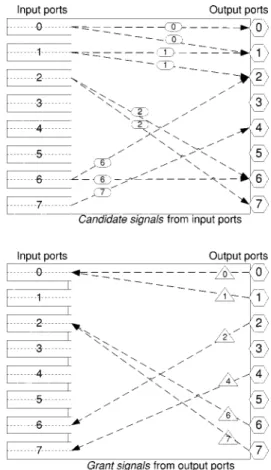
Fig. 1. Candidate signals and grant signals.
related output ports. An example is given in the upper part of Fig. 1, where five input ports send out candidate signals to six output ports.
2) When an output port receives candidate signals from different input ports, it chooses one randomly among these input ports. A grant signal, containing the iden-tifier of this output port, sends back to the chosen input port. The lower part of Fig. 1 shows the result for an ex-ample.
3) When an input port receives the grant signals, it sends out the granted packets to the output ports. More than one packets are allowed to be sent out from an input port, and the internetwork is assumed to be able to handle this situation.
Some properties for this algorithm can be obtained as follows. 1) Because of no buffers in output ports, at most one packet
can be sent to each output port during each time slot. 2) More than one packet can be sent out from each input
port during each time slot. To meet the requirement of this algorithm, the access speed of the internetwork is times faster than that of input ports; otherwise, copies of the internetwork are used if the access speed is not faster. 3) Each of the above three steps can be parallelized. In the
first step, all nonempty input ports can send out candidate signals simultaneously. In the second step, all signaled output ports can make decisions simultaneously. In the last step, all chosen input ports can again send out packets simultaneously.
TABLE I SWITCHTHROUGHPUT
4) Given any scenario, the number of transmitted packets by this algorithm is not fewer than that of the maximum matching algorithm. That is, this algorithm outperforms the maximum matching in terms of the number of trans-mitted packets. The detailed proof by graph theory can be found in [11], and its concept is given here. The number of resulting pairs, (input port , output port ), by the max-imum matching algorithm, is the same as that by our al-gorithm if eachoutput port ’s degree is unity, or is fewer than that by our algorithm if anyoutput port ’s degree is larger than one because we can find one or more new pairs from this output port.
IV. ANALYSIS ANDSIMULATION
For a switch with buffers in each input port,
switch throughput, can be defined as the utilization of output trunk when the system is fully loaded. It can be also viewed as the throughput of unbuffered switches under uniform Bernoulli traffic, which is the upper bound of buffered switches under the same traffic [2].
For each input port, if is the number of head-of-buffer
packets, clearly and some values can be obtained
as follows.
1) The number of possible combinations of ports chosen from output ports at a time is .
2) The number of possible combinations of ports chosen from output ports at a time is if a particular output port is chosen already.
3) The possibility of any input port sending a
candidate signal to a particular output port is .
WU AND LIN: NOVEL PAIRING ALGORITHM FOR HIGH-SPEED LARGE-SCALE SWITCHES 25
4) For a particular output port, the probability, denoted by , of receiving at least one candidate signal is
. Clearly is when .
5) Switch throughput is . Hence, it is
for a switch and approach
when .
Table I shows the values of and our
simu-lation result. An unbuffered switch with buffers in each input port is simulated, and 107packets are generated randomly for each pair. Both analysis and simulation show almost the same result and perform very well when . In fact, the switch throughput reaches 0.981, i.e., , when the
switch size .
V. CONCLUSION
Many researchers [3]–[10] focus on reducing HOL blocking to improve the throughput of input-queued switches; however, the poor performance, 0.632, of the maximum matching is also an important factor for poor performance, 0.586, of input-queued switches [2]. The proposed algorithm can boost
the switch capacity to 0.981 from 0.632 when and
.
ACKNOWLEDGMENT
The authors would like to acknowledge Prof. T.-H. Lee, De-partment of Communication Engineering, National Chiao Tung
University, Hsinchu, Taiwan, R.O.C., for his helpful discussion on ATM switches.
REFERENCES
[1] M. Schwartz, Broadband Integrated Networks. Englewood Cliffs, NJ: Prentice-Hall, 1996, ch. 5, pp. 182–208.
[2] M. Karol and M. Hluchyj, “Input versus output queueing in a space di-vision switch,” IEEE Trans. Commun., vol. COM-35, pp. 1347–1356, 1987.
[3] G. Thomas, “Improved windowing rule for input buffered packet switches,” Electron. Lett., vol. 29, pp. 393–395, 1993.
[4] R. Y. Awdeh and H. T. Mouftah, “Survey of atm switch architectures,”
Computer Networks ISDN Syst., vol. 27, pp. 1567–1613, 1995.
[5] J.-J. Li, “Improving the input-queueing switch under bursty traffic,”
Electron. Lett., vol. 31, pp. 854–855, 1995.
[6] N. McKeown, V. Anantharam, and J. Walrand, “Achieving 100% throughput in an input-queued switch,” in Proc. IEEE Infocom, San Francisco, CA, pp. 3A.4.1–3A.4.6.
[7] G. Nong, J. K. Muppala, and M. Hamdi, “A performance model for atm switches with multiple input queues,” in Proc. IEEE ICCCN, Las Vegas, NV, 1997, pp. 222–227.
[8] N. K. Sharma and M. R. Pinnu, “An efficient implementation of bypass queue under bursty traffic,” Parallel Computing, vol. 23, pp. 777–781, 1997.
[9] G. Thomas, “Bifurcated queueing for throughput enhancement in input-queued switches,” IEEE Commun. Lett., vol. 1, pp. 56–57, 1997. [10] J. S.-C. Wu and Y.-D. Lin, “An efficient and orderly implementation
of bypass queue under bursty traffic,” Parallel Computing, vol. 24, pp. 2143–2148, 1998.
[11] J. S.-C. Wu, “Cell sequence guarantee and maximum pairing for large scale input-queued switches,” M.S. thesis, National Chiao Tung Univer-sity, HsinChu, Taiwan, 1998.