Probing the evolution of antiferromagnetism in multiferroics
M. B. Holcomb,1,2L. W. Martin,3,4A. Scholl,5Q. He,1P. Yu,1C.-H. Yang,1S. Y. Yang,1 P.-A. Glans,5M. Valvidares,3 M. Huijben,6J. B. Kortright,5J. Guo,5 Y.-H. Chu,1,7 and R. Ramesh1,3,8,
*
1Department of Physics, University of California–Berkeley, Berkeley, California 94720, USA 2Department of Physics, West Virginia University, Morgantown, West Virginia 26506, USA 3Materials Science Division, Lawrence Berkeley National Laboratory, Berkeley, California 94720, USA
4Department of Materials Science and Engineering, Frederick Seitz Materials Research Laboratory,
University of Illinois at Urbana–Champaign, Urbana, Illinois 61801, USA
5Advanced Light Source, Lawrence Berkeley National Laboratory, Berkeley, California 94720, USA
6Faculty of Science and Technology, MESA⫹ Institute for Nanotechnology, University of Twente, Enschede 7500 AE, The Netherlands 7Department of Materials Science and Engineering, National Chiao Tung University,
HsinChu, Taiwan 30010, Republic of China
8Department of Materials Science and Engineering, University of California–Berkeley, Berkeley, California 94720, USA
共Received 29 June 2009; revised manuscript received 4 March 2010; published 6 April 2010兲
This study delineates the evolution of magnetic order in epitaxial films of the room-temperature multiferroic BiFeO3system. Using angle- and temperature-dependent dichroic measurements and spectromicroscopy, we have observed that the antiferromagnetic order in the model multiferroic BiFeO3evolves systematically as a
function of thickness and strain. Lattice-mismatch-induced strain is found to break the easy-plane magnetic symmetry of the bulk and leads to an easy axis of magnetization which can be controlled through strain. Understanding the evolution of magnetic structure and how to manipulate the magnetism in this model mul-tiferroic has significant implications for utilization of such magnetoelectric materials in future applications. DOI:10.1103/PhysRevB.81.134406 PACS number共s兲: 75.70.Ak, 75.50.Ee, 78.70.Dm, 77.80.Dj
Magnetoelectric multiferroics are the focus of much ex-perimental and theoretical research1–5 due to their potential
to greatly impact emerging fields of study such as spin-based electronics共spintronics兲 and new forms of magnetic storage, logic, and memory devices.5,6An ideal multiferroic would be a ferroelectric, ferromagnet that exhibits strong coupling be-tween these order parameters at room temperature. To date, such a material system has not emerged; instead, there is a strong focus on antiferromagnetic, ferroelectrics such as BiFeO3 共BFO兲 that can be coupled to ferromagnetic materi-als to achieve the desired coupling between electric fields and ferromagnetism at room temperature.6–10
To enable the design of such devices based on multiferro-ics, it is essential to understand the nature of the various order parameters especially in thin-film samples. While con-ventional measurements, such as scanning probe microscopy and quantitative polarization-electric field measurements can probe the evolution of the ferroelectric order parameter, probing the corresponding antiferromagnetic component in a multiferroic material is only achievable through optical probes or neutron scattering.1,11,12Additionally, when a
mul-tiferroic is grown as an epitaxial thin film for potential de-vice applications, the antiferromagnetic state can evolve as a function of the constraints imposed by reduced dimensional-ity as well as from the strain imposed by the substrate.13 In
this paper, we explore the evolution of antiferromagnetism, specifically the development of a preferred magnetic axis in thin films of the model multiferroic BFO using state-of-the-art photoemission based spectromicroscopy at the Advanced Light Source, Lawrence Berkeley National Laboratory.
BFO is one of the most widely studied multiferroic mate-rials over the last decade largely because it is the only single-phase multiferroic material that is simultaneously both anti-ferromagnetic and ferroelectric at room temperature 关Néel
temperature 共TN兲⬃643 K and ferroelectric Curie tempera-ture共TC兲⬃1103 K兴.14,15This makes BFO an ideal candidate
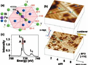
for use in room-temperature applications. BFO is a rhombo-hedrally distorted perovskite ferroelectric with large intrinsic polarization16 and eight possible polarization directions oc-curring along the pseudocubic具111典 body diagonals, one of which is shown in Fig.1共a兲. It is also known to be a G-type, canted antiferromagnet,16 which means that the individual
FIG. 1. 共Color兲 Understanding order parameters in multiferroic BFO. 共a兲 Schematic of 共001兲-oriented BFO crystal structure with polarization along具111典 and predicted perpendicular easy magnetic plane for the bulk 共shown as red hexagon兲. 共b兲 PFM image of in-plane polarization projections with PFM and PEEM geometries 共taken separately兲, showing incident x rays 30° from sample sur-face.共c兲 Absorption spectra of iron edge showing selected imaging energies.
111-type plane, which is perpendicular to a given具111典-type polarization direction,20 shown as the transparent red plane
in Fig. 1共a兲. Thus, one critical question concerning magne-tism in multiferroics such as BFO that is of both fundamental and technological importance is how this order parameter develops with strain and size effects? In this paper, we report that a systematic evolution of the state of magnetism is in-deed accomplished through the imposition of a compressive 共or tensile兲 strain on the bulk material. Our particular path-way is through an epitaxial constraint imposed by the sub-strate. We use angle-resolved, temperature-dependent photo-emission electron microscopy 共PEEM兲 to establish the fundamental nature of the magnetic state in BFO.
Single phase, epitaxial thin films of BFO were grown on a 50-nm-thick bottom electrode of SrRuO3 共SRO兲 on SrTiO3 共STO兲 共001兲 single-crystal substrates via laser-molecular-beam epitaxy and metalorganic chemical-vapor deposition. Detailed x-ray diffraction studies coupled with transmission electron microscopy were used to establish the crystalline quality of the heterostructures; these films were found to be single phase and fully epitaxial. This paper explores the evo-lution of magnetism that occurs in these BFO films. Throughout this paper we refer to two classes of films—thin films that have thickness 共t兲 between 20 and 200 nm and thick films that have t⬃1 m.
A combination of in-plane and out-of-plane piezoresponse force microscopy共PFM兲 allows two-dimensional mapping of the ferroelectric polarization directions in a material.21
De-tails of the measurements are reported by Zavaliche, et al.21
The in-plane ferroelectric domain structure of a typical BFO thin film is shown in Fig.1共b兲; the long axis of the ferroelec-tric domains共or direction of the domain walls兲 lies along the 具100典 of the underlying STO 共001兲 substrate or the pseudocu-bic 具100典 of BFO. The polarization direction of the various stripelike domains lies along the具111典 and the in-plane pro-jection of those polarization directions lie along the 具110典. The arrows in Fig.1共b兲refer to the in-plane projection of the ferroelectric polarization directions共four variants兲 present in this model system. Such a model ferroelectric domain struc-ture forms the reference frame for our photoemission measurements.
Synchrotron-based x-ray absorption and PEEM have emerged as powerful tools that provide chemically specific insight into the nature of magnetic order in materials.22–24
Soft x-ray absorption experiments were performed at the el-liptically polarizing undulator beamline 11.0.1 at the Ad-vanced Light Source of Lawrence Berkeley National
Labo-images were obtained at ⫾0.5 eV from the Fe L3,B edge. The d-shell properties largely responsible for the magnetism of transition metals and oxides are probed through 2p to 3d dipole transitions, i.e., L3,2absorption spectra关Fig.1共c兲兴. The
L-edge spectra depend on anisotropies in the charge or the
spin in the material, and thus are sensitive to the relative orientation of the x-ray polarization and antiferromagnetic axes which are then imaged by PEEM. Recognizing that x-ray linear dichroism共XLD兲 can arise from any anisotropic distribution of charge in a material共as would be the case for both ferroelectric and antiferromagnetic order兲, we have de-coupled the contributions from these sources unambiguously through temperature- and angle-dependent measurements.
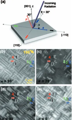
Figure 2共a兲illustrates the x-ray polarization geometry in which the XLD-PEEM images in Figs.2共b兲–2共e兲were taken. The images in Figs. 2共b兲–2共e兲 are from the corresponding area shown in Fig.1共b兲; for example, the “T” shaped domain in Figs. 1共b兲 and 2共b兲 is outlined as an aid to the reader. Images result from dividing intensity maps taken at the A and B multiplet peaks of the Fe L3 absorption edge using linearly polarized light as the angle of the plane of linear incident polarization 共␣兲 varies from 0° 共p polarization兲 to 90° 共s polarization兲. The outlined arrows in Fig.2 show the in-plane projection of the four ferroelectric directions. When the x rays are s polarized共␣= 90°兲, only two contrast scales 关labeled as light 共1 and 3兲 and dark 共2 and 4兲 in Fig.2共b兲兴 are observed. We have chosen a geometry such that the x-ray polarization vector for an s-polarized incident beam is along 关1¯10兴, which maximizes the difference in intensity between the domains. In this geometry, the propagation vector of the incident x rays is nearly parallel to 关111¯兴 due to the= 30° grazing angle from the sample surface 关as shown in Fig. 2共a兲兴. Figures2共b兲–2共e兲were obtained by changing the x-ray polarization angle␣and keeping the grazing incidence angle fixed, which allowed us to gain insight into the magnetic structure by plotting the ␣-angle dependence of the x-ray dichroic signal. Individual ferroelectric polarization direc-tions can be preferentially identified by rotating the x-ray polarization relative to the crystal as demonstrated in Fig. 2共c兲. For example, in Fig. 2共c兲, the technique highlights all 关1¯11¯兴-type ferroelectric domains 共black arrow兲. The angle dependence reveals that at ␣= 70°, three of the four 具1 1 1典-type domains have similar contrast while the inten-sity from关1¯11¯兴 domains is much higher. Further rotation of the polarization to ␣= 40° 关Fig. 2共d兲兴 results in an image where all four ferroelectric variants can be distinguished due to their differences in contrast. Contrast between certain
do-main types can also vanish at other x-ray polarization angles—such as the 关11¯1¯兴 and 关1¯11¯兴-type domains in Fig. 2共e兲for ␣= 0.
Focusing on the image in Fig.2共c兲, where we have con-trolled the relative orientation of the incidence x-ray polar-ization and the crystallographic orientation of BFO to pref-erentially observe one ferroelectric polarization direction共in this case all ferroelectric domains of the关1¯11¯兴 type兲, we gain insight into the nature of magnetism in BFO. We note again that all individual domains of a specific ferroelectric polar-ization direction exhibit identical contrast. This indicates that the antiferromagnetic order in a given set of identical ferro-electric domains is the same. This automatically rules out the possibility of a magnetic structure such as that in a bulk sample of BFO in which there is a 111-type easy plane of magnetization perpendicular to the polarization direction. PEEM imaging in this geometry would result in multiple contrast levels for a given set of identical ferroelectric do-mains if the antiferromagnetic dodo-mains were larger then the PEEM resolution共⬃30 nm兲. The formation of antiferromag-netic domains with sizes smaller than 30 nm is highly un-likely, purely due to energetic considerations, as is verified in the following measurements.22 Therefore, the data in Fig.
2共c兲is consistent with a magnetic structure in which an easy magnetic axis is formed in the兵111其-magnetization plane of BFO similar to what is observed in strained NiO films.25
Simple models of the x-ray polarization angle共␣兲 depen-dence of the dichroic domain contrast共Fig.3兲 further support this conclusion. From a series of images 关such as those in Figs.2共b兲–2共e兲兴, we can extract the␣dependence of dichroic contrast共from both ferroelectric and magnetic contributions兲 for thin 关Fig. 3共a兲兴 and thick 关Fig. 3共b兲兴 films and compare this data to model calculations as a function of the x-ray polarization angle␣. The corresponding series of images for a prototypical thick BFO film have been included as an inset in Fig.3共b兲 and illustrate similar stripelike images that cor-respond directly with PFM images. The PEEM images dem-onstrate no discernible magnetic variation within a given ferroelectric domain, illustrating the importance of the need to model different magnetic behaviors. The angle depen-dence of the magnetic contribution to linear dichroism of an antiferromagnet has been modeled26previously as
I =共3 cos2⍜M− 1兲具M2典T, 共1兲 where M is the magnetic moment at a temperature T and⍜M is angle between the antiferromagnetic axis and the incident x-ray polarization vector axis. The ferroelectric contribution is also thought to exhibit a cosine-squared angular dependence21,27 on the angle ⍜F between the ferroelectric
polarization axis and the x-ray polarization axis. Therefore, we have modeled the dichroism from a multiferroic material with both magnetic and ferroelectric order when linearly po-larized light is incident upon the sample at a given tempera-ture as
IXLD= P cos2⍜F+ Q cos2⍜M, 共2兲
FIG. 2. 共Color兲 PEEM images of BFO at several angles of the electric vector of incident linear polarization␣. 共a兲 Schematic illus-trating the experimental geometries used to probe the angle-dependent linear dichroism in BFO. The outlined arrows show the in-plane projection of the four ferroelectric directions. Images of domain structures taken at共b兲␣=90°, 共c兲 ␣=70°, 共d兲 ␣=40°, and 共e兲␣=0°.
FIG. 3. 共Color兲 Comparison between experimentally measured and modeled angle-dependent XLD contrast. Experimentally mea-sured dichroic contrast as the x-ray polarization is rotated for both 共a兲 thin and 共b兲 thick BFO films. Error for all data points is less than 4% of the observed maximum contrast difference. The insets in共b兲 are the corresponding images for the data on the thick BFO films taken at the same experimental geometries as the thick films. Mod-els of XLD contrast for two magnetic structures,共c兲 a unique mag-netic axis and共d兲 an easy magnetic plane, are shown for the same sample orientation as in Fig.2.
these directions, and other possible directions not limited to that magnetization plane.
Models of the x-ray polarization angle dependence of the dichroic contrast for the two candidate magnetic structures previously discussed—a unique magnetic axis versus an easy magnetic plane—are shown in Figs. 3共c兲and 3共d兲, respec-tively. By comparing the experimentally measured dichroic contrast关Figs.3共a兲and3共b兲兴 with that of the calculated angle dependencies, a clear correlation emerges. For thin films, the data clearly indicates an easy magnetic axis is present in the film while in contrast, for thick films, the data strongly sug-gests an easy magnetic plane is present. We note that data for only two variants are presented for the thick films due to experimental constraints in producing thick films with four variants. Regardless, clear differences in the magnetic struc-ture between thin and thick BFO films are observed, present-ing the first evidence for the formation of an easy or pre-ferred magnetic axis in epitaxially strained thin films of BFO. It should be noted that small deviations between the experimentally observed data and these simple models could originate from the fact that only the dominating contributions to dichroism 共in this case, magnetism and ferroelectricity兲 have been utilized in the study. Prior studies have suggested the importance of other factors, such as the orientation of the crystallographic axis.28 These additional factors will not,
however, change the major conclusions of this analysis. The angle-dependent data and model for thin films of BFO关Figs.3共a兲and3共c兲兴 can only be achieved by two types of easy axes:关11¯0兴 and 关112兴 for a given 关111¯兴-polarization direction. The image contrast for these two scenarios can look the same due to the fact that P and Q in Eq. 共2兲 are variables. However, previous temperature-dependent mea-surements have shown that the percentage of the dichroism at room temperature originating from the ferroelectric polar-ization 共P兲 is approximately 60⫾10%.29 Therefore, we
present the results of our modeling from this range since it reasonably reflects the dependence of the observed data. In order to uniquely identify this axis, we have carried out temperature-dependent measurements.
The two possible types of easy axes, 具11¯0典 and 具112典, should exhibit different temperature dependence of the inten-sity distribution when imaged, for instance, at ␣= 0° 关Fig. 2共a兲兴. For the case of a 具11¯0典 preferred axis, the magnetic axis for the domains with the largest contrast 关2 and 4 at dashed line e in Fig. 3共a兲兴 is perpendicular to the electric field vector of the incident x rays. Thus, the difference be-tween these two domains is dependent only on the
contribu-to zero at the Néel temperature. From this, one can then estimate a⬃40% reduction in total intensity at the Néel tem-perature 共370 °C兲 and, by interpolation, a ⬃20% reduction in contrast should be achieved from room temperature to 200 ° C. A full temperature dependence study to temperature above TN is not essential as strong temperature dependent changes in contrast are observed well before that tempera-ture.
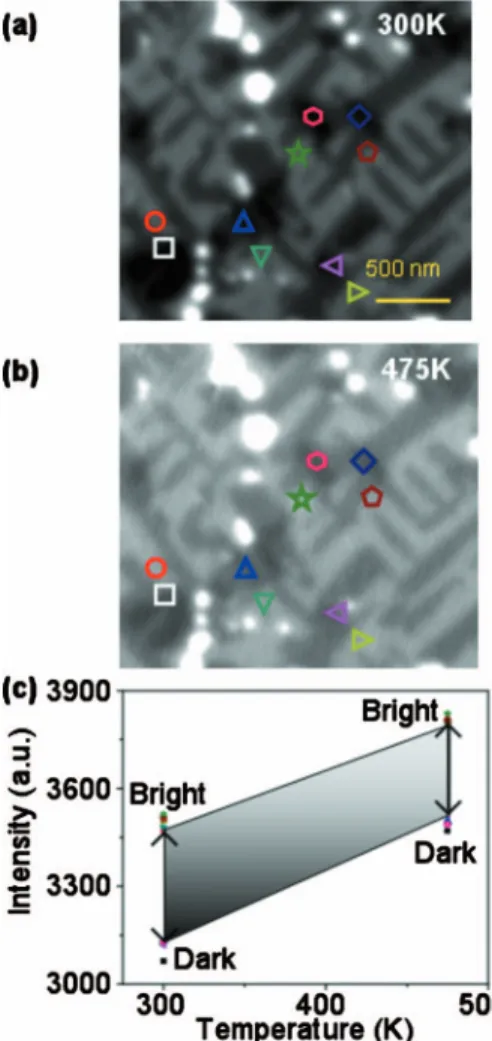
Figure 4 illustrates the contrast between these domains 共2—light gray and 4—black兲 that has been repeatedly taken at room temperature 关Fig. 4共a兲兴 and at 200 °C 关Fig. 4共b兲兴. These images exhibit four shades—white, light gray, me-dium gray, and black. Light gray and black correspond to the domains with the largest contrast 共domains 2 and 4兲, whose temperature dependence determines which magnetic axis is present. The medium gray is achieved for both 1 and 3 do-mains. As illustrated by the several 2/4 locations plotted in Fig.4共c兲, the contrast was found to decrease by⬃17% upon heating, which is in reasonable agreement with the 具112典 easy-axis scenario. Continued contrast reduction was ob-served at higher temperatures but sample damage at these temperatures began to threaten sample integrity and therefore we have not included data beyond 200 ° C. We have com-pleted measurements on both films capped with a 2-nm-thick layer of SRO and uncapped BFO films preheated for 1 hour at 200 ° C in an attempt to minimize the impact of any sur-face chemistry effects; however, the same trend as expected for the具112典 case was observed in all cases.
It is important to understand the driving force for this change in the magnetic structure in BFO. Strain-driven changes in magnetic structure have been observed previously in other magnetic oxide systems which exhibit a strong cou-pling among spin, charge, orbital, and lattice degrees of free-dom. For example, strain has a strong effect on colossal mag-netoresistance manganites. Strain-induced changes to the double-exchange ferromagnetism in these materials have been interpreted by considering the variation in the elec-tronic hopping amplitude due to the change in bond lengths and bond angles.30Strain has also been shown to affect the
nature of antiferromagnetic superexchange coupling in ox-ides such as NiO. Like BFO, NiO has an easy共111兲 magnetic plane. In the presence of strain, however, uniaxial anisotropy allows the formation of an easy axes with that plane, parallel to either 关110兴 共nearest neighbor兲 or 关112兴 共next nearest neighbor兲.25In NiO it has been suggested that an
orthorhom-bic contraction 共i.e., that which would result from an in-plane compressive strain兲 along 关100兴 favors a 具110典 easy axis; whereas a monoclinic expansion共i.e., that which would
result from an in-plane tensile strain兲 along 关110兴 favors a 具112典 easy axis.31
Epitaxial growth of BFO thin films on STO 共001兲 sub-strates results in a similar strain effect on the antiferromag-netism. The lattice mismatch between BFO and STO 共1.54%兲 imparts a compressive in-plane strain to the BFO film that is progressively relaxed as the film thickness is increased.32Using x-ray reciprocal-space mapping共RSM兲 of
the 203 BFO diffraction peak as shown in Figs.5共a兲and5共b兲 we have studied the strain state in such films as a function of film thickness. The in-plane 共a兲 and out-of-plane 共c兲 lattice parameters as well as the monoclinic tilt angle共兲 are shown in the table along with a schematic describing the nature of the structural distortions关Figs.5共c兲and5共d兲兴. In the case of a 200-nm-thick BFO/SRO/STO共001兲 film, the in-plane lat-tice parameters are matched with those of the substrate and the unit cell is under compressive strain 共c/a=1.039兲 关Fig. 5共a兲兴. As the film thickness is increased to 1 m, the lattice parameters gradually approach the bulk BFO value and the
pseudotetragonality 共c/a=1.005兲 becomes smaller 关Fig. 5共b兲兴.  is derived from the peak splitting of the 203 peak and is calculated to be ⬃0.74°, close to the value measured in bulk BFO. The in-plane compressive strain lifts the degen-eracy of magnetization in the 111 plane, as is also observed in the case of NiO thin films.25 This preferred axis can also
be understood in terms of the magnetostriction in BFO. The magnetostriction constant of BFO is positive,33meaning that
the lattice constants expand along an applied magnetic field. Substrate-induced compressive strain is effectively the oppo-site of this effect and thus results in a preference of a mag-netization direction that has the largest out-of-plane compo-nent while remaining in the 共111¯兲, i.e., the 具112典. This is consistent with the calculations for NiO, which has the op-posite sign of magnetostriction from BFO, and therefore demonstrates the opposite preferential magnetic 具110典 axis when under compressive strain.31 Additionally, preliminary
findings suggest that BFO films under tensile strain共for ex-ample, by epitaxial growth on Si兲 have a 具11¯0典 easy mag-netic axis. This demonstrates that one can control the nature the magnetic axis in such multiferroic thin films and in turn use this ability to better engineer a new generation of devices that utilize electric field driven changes in magnetic order.
In conclusion, the evolution of magnetism in multiferroic BFO is clearly a complex and intriguing subject. Through a careful experimental and theoretical study of PEEM images and the underlying structure of BFO, we have determined that epitaxially strained thin films do not show a degenerate magnetic plane as predicted for bulk, but instead exhibit the formation of a preferred magnetic axis depending on the na-ture of strain 共具112典 or 具11¯0典 for compressive and tensile strain, respectively兲. In compressively strained BFO 共001兲 thin films, the antiferromagnetic direction lies along the 具112典 axes. This axis points as far out of the surface plane as possible while remaining perpendicular to the polarization direction. The following polarization directions 兵关111¯兴, 关11¯1¯兴, 关1¯11¯兴, and 关1¯1¯1¯兴其 have the corresponding axes 兵关112兴, 关11¯2兴, 关1¯12兴, and 关1¯1¯2兴, respectively其. Thick films no longer
FIG. 4. 共Color兲 Temperature-dependent dichroism measure-ments of BFO. XLD images taken at共a兲 room temperature and 共b兲 200 ° C. The labeled spots in共a兲 and 共b兲 represent a selection of locations used to probe the temperature-dependent change in di-choric contrast.共c兲 Temperature-dependent changes in intensity for type 2 and 4 domains for both temperatures reveals that the differ-ence between the contrast from type 2 and 4 domains reduces by 17% at 200 ° C. This is expected for the presence of a preferred magnetic关112兴 axis.
FIG. 5.共Color兲 The crystal structure of thin and thick BFO films grown on SRO/STO共001兲. RSMs for 共a兲 thin and 共b兲 thick BFO grown on SRO/STO共001兲. 共c兲 Schematic illustrating the nature of the crystal structure of the BFO film, where a is the in-plane lattice parameter, c is the out-of-plane lattice parameter, and  is the monoclinic distortion angle.共d兲 Unit-cell parameters, as determined by RSM, for both strained共thin兲 and relaxed 共thick兲 films.
*mikel.holcomb@mail.wvu.edu
1M. Fiebig,J. Phys. D 38, R123共2005兲.
2W. Eerenstein, N. D. Mathur, and J. F. Scott, Nature共London兲
442, 759共2006兲.
3S.-W. Cheong and M. Mostovoy,Nature Mater. 6, 13共2007兲. 4R. Ramesh and N. A. Spaldin,Nature Mater. 6, 21共2007兲. 5H. Bea, M. Gajek, M. Bibes, and A. Barthelemy,J. Phys.:
Con-dens. Matter 20, 434221共2008兲.
6P. Borisov, A. Hochstrat, X. Chen, W. Kleemann, and C. Binek, Phys. Rev. Lett. 94, 117203共2005兲.
7X. Martí, F. Sánchez, J. Fontcuberta, M. V. García-Cuenca,
C. Ferrater, and M. Varela,J. Appl. Phys. 99, 08P302共2006兲. 8J. Dho, X. Qi, H. Kim, J. L. MacManus-Driscoll, and M. G.
Blamire,Adv. Mater. 18, 1445共2006兲.
9V. Laukhin, V. Skumryev, X. Martí, D. Hrabovsky, F. Sánchez,
M. V. García-Cuenca, C. Ferrater, M. Varela, U. Lüders, J. F. Bobo, and J. Fontcuberta,Phys. Rev. Lett. 97, 227201共2006兲. 10H. Béa, M. Bibes, F. Ott, B. Dupé, X. H. Zhu, S. Petit, S. Fusil,
C. Deranlot, K. Bouzehouane, and A. Barthélémy, Phys. Rev. Lett. 100, 017204共2008兲.
11A. Pimenov, A. A. Mukhin, V. Yu. Ivanov, V. D. Travkin, A. M.
Balbashov, and A. Loidl,Nat. Phys. 2, 97共2006兲.
12D. Lebeugle, D. Colson, A. Forget, M. Viret, A. M. Bataille, and
A. Goukasov,Phys. Rev. Lett. 100, 227602共2008兲.
13C. A. F. Vaz, J. A. C. Bland, and G. Lauhoff,Rep. Prog. Phys.
71, 056501共2008兲.
14C. Michel, J.-M. Moreau, G. D. Acheubach, and W. J. James, Solid State Commun. 7, 701共1969兲.
15P. Fischer, M. Polomska, I. Sosnowska, and M. Szymanski, J. Phys. C 13, 1931共1980兲.
16S. V. Kiselev, R. P. Ozerov, and G. S. Zhdanov, Sov. Phys. Dokl. 7, 742共1963兲.
17S. Lisenkov, D. Rahmedov, and L. Bellaiche, Phys. Rev. Lett.
103, 047204共2009兲.
18I. E. Dzyaloshinskii, Sov. Phys. JETP 5, 1259共1957兲. 19T. Moriya,Phys. Rev. 120, 91共1960兲.
20C. Ederer and N. A. Spaldin, Phys. Rev. B 71, 060401共R兲 共2005兲.
21F. Zavaliche, S. Y. Yang, T. Zhao, Y. H. Chu, M. P. Cruz, C. B.
Eom, and R. Ramesh,Phase Transitions 79, 991共2006兲. 22J. Stohr and H. C. Siegmann, Magnetism From Fundamentals to
Nanoscale Dynamics共Springer, New York, 2006兲.
23A. Scholl, H. Ohldag, F. Nolting, J. Stohr, and H. A. Padmore, Rev. Sci. Instrum. 73, 1362共2002兲.
24G. Cressy, C. M. B. Henderson, and G. van der Laan, Phys.
Chem. Miner. 20, 111共1993兲.
25H. Ohldag, A. Scholl, F. Nolting, S. Anders, F. U. Hillebrecht,
and J. Stohr,Phys. Rev. Lett. 86, 2878共2001兲.
26J. Stöhr, A. Scholl, T. J. Regan, S. Anders, J. Lüning, M. R.
Scheinfein, H. A. Padmore, and R. L. White, Phys. Rev. Lett.
83, 1862共1999兲.
27T. Tsuboi,Phys. Rev. B 39, 2842共1989兲.
28G. van der Laan, E. Arenholz, R. V. Chopdekar, and Y. Suzuki, Phys. Rev. B 77, 064407共2008兲.
29T. Zhao, A. Scholl, F. Zavaliche, K. Lee, M. Barry, A. Doran,
M. P. Cruz, Y. H. Chu, C. Ederer, N. A. Spaldin, R. R. Das, D. M. Kim, S. H. Baek, C. B. Eom, and R. Ramesh, Nature Mater. 5, 823共2006兲.
30A. J. Millis, A. Migliori, and T. Darling,J. Appl. Phys. 83, 1588 共1998兲.
31T. Yamada,J. Phys. Soc. Jpn. 21, 664共1966兲.
32Y. H. Chu, T. Zhao, M. P. Cruz, Q. Zhan, P. L. Yang, L. W.
Martin, M. Huijben, C. H. Yang, F. Zavaliche, H. Zheng, and R. Ramesh,Appl. Phys. Lett. 90, 252906共2007兲.
33A. K. Zvezdin, A. M. Kadomtseva, S. S. Krotov, A. P. Pyatakov,
Yu. F. Popov, and G. P. Vorob’ev,J. Magn. Magn. Mater. 300, 224共2006兲.
34Y. H. Chu, L. W. Martin, M. B. Holcomb, M. Gajek, S.-J. Han,
Q. He, N. Balke, C.-H. Yang, D. Lee, W. Hu, Q. Zhan, P.-L. Yang, A. Fraile-Rodriquez, A. Scholl, S. X. Wang, and R. Ramesh,Nature Mater. 7, 478共2008兲.