IEEE TRANSACTIONS ON POWER ELECTRONICS, VOL. 11, NO. 4, JULY 1996 567
Discrete Sliding-Mode Control
of
a PWM
Inverter
for
Sinusoidal Output Waveform
Synthesis with Optimal Sliding Curve
Shih-Liang Jung, Student Member, IEEE, and Ying-YuTZOU,
Member, IEEEAbstract-This paper presents a discrete sliding-mode control scheme with feedforward compensation for the closed-loop regu- lation of the pulse-width modulated (PWM) inverter used in an uninterruptible power supply (UPS). The proposed feedforward controller can effectively improve the tracking performance of the PWM inverter. In designing the sliding-mode controller, we have taken load disturbance into consideration to enhance the robustness of the PWM inverter. Moreover, the upper bound of the load disturbance under which the sliding condition can be maintained has also been derived. The sliding curve of the sliding-mode controller is designed such that the behavior of the controlled PWM inverter is optimal subject to the selected cost function. Due to the coordinate transformation proposed in this paper, only the output voltage needs to be measured as feedback for the purpose of closed-loop regulation. Simulation and experimental results are given to show the effectiveness of the proposed control scheme.
I. INTRODUCTION
MONG all power converters, the pulse-width modulated
A
(PWM) inverter has the most widespread applications in industry, such as power supply, phase-controlled rectifier, and adjustable speed ac servo drives. Besides, the closed- loop controlled PWM inverter with LC filters has a special application in uninterruptible power supply (UPS) [I]. The basic function of an UPS is to convert the dc voltage of batteries to sinusoidal ac voltage with specified frequency and amplitude in the case of utility power failure. Fig. 1 shows the functional block diagram of a digital-controlled UPS system used for ac power conditioning. Since the PWM inverter plays an important role in converting the dc voltage source to an ac voltage source, the quality of the output waveform of an UPS is highly dependent on the performance of the PWM inverter. In order to minimize the total harmonic distortion (THD) ofthe output voltage of a PWM inverter, the output transformer coupled stepped waveform and the programmed PWM tech- niques were used to suppress the lower order harmonics [2], [3]. Though these strategies have good steady state characteris- tics, they are not suitable for the applications with sudden load change because of the lack of closed-loop regulation. Some closed-loop control schemes with instantaneous feedback us- ing analog techniques were proposed to improve the transient
Manuscript received July 18, 1996; revised April 8, 1996.
The authors are with the Department of Control Engineering, National Publisher Item Identifier S 0885-8993(96)05167-8.
Chiao Tung University, Hsinchu 30050, Taiwan, Republic of China.
response caused by load variation at the expense of compli- cated control circuitry [4],
[5].
With successively improving reliability and performance of microprocessors, digital control techniques have taken over many industrial applications from analog ones in the past decade. The microprocessor-based deadbeat control scheme has been applied to the closed-loop control of PWM inverters [6], [ 7 ] . However, the deadbeat strat- egy has the disadvantage of being sensitive to the parametric variation of the controlled system.The variable structure system with sliding mode was first proposed in the 1950’s. Essentially, the sliding-mode control system utilizes a switching control law to drive the state of the concerned syslem to a predesigned curve (also called the sliding curve) in the phase plane, and then keep the state sliding over there in the subsequence [SI. The sliding- mode strategy provides a systematic approach to the problem of maintaining stability and performance in the presence of modeling uncertainty [9]. The most distinguished feature of a sliding-mode control system is its insensitivity to parametric uncertainty and external disturbances. Therefore, the sliding- mode control scherne is especially suitable for the closed-loop control of power converting systems under load variation. Many researchers have paid attention to the application of sliding-mode control scheme to power converters through analog techniques [lo], [ 111. Analog realization of sliding- mode controllers may result in higher stress of the switch- ing devices and more complicated hardware. Microprocessor- based software realization can reduce the hardware complexity of the sliding-mode controller. However, since the design philosophy of the analog sliding-mode method cannot be directly extended to discrete-time cases, the sampling action of the microprocessor may bring chattering phenomenon or instability to the analogously designed sliding-mode control system. Therefore. a pure discrete sliding-mode technique will be necessary if a microprocessor is used to realize the corresponding control law. Recently, discrete sliding-mode control (DSMC) has drawn much attention [12]-[15]. The results are quite (different from those of the conventional analog sliding-mode control theory. The switching frequency of the discrete sliding-mode controller is finite. The finite- frequency operation makes the DSMC algorithm suitable for digital realization. 4 DSMC scheme for the regulation of servo systems was proposed by Chan [13], and its modified version 0885-8993/96$05.00 0 1996 IEEE
568 IEEE TRANSACTIONS ON POWER ELECTRONICS, VOL. 11, NO. 4, JULY 1996
w Line ~
Booster + Inverter + Filter
, ,
4 4 4
\ M I
II n n 1
I
, ,
Microprocessor-based digital controller
,
, _ _ ~ ~ ~ ~ _ ~ ~ ~ ~ ~ ~ ~ ~ . . . _ ~ . . ~ ~ ~ ~ ~ ~ ~ ~ ~ ~~~
Fig. 1. The functional block diagram of a digital-controlled UPS system.
Vi
Fig. 2. PWM inverter used in UPS systems.
has been applied to the closed-loop regulation of a PWM inverter by Jung and Tzou [ 161. The resultant output waveform in [16] has good transient characteristics as load varies, but the steady-state response is poor.
This paper presents a discrete feedforward sliding-mode control (DFSMC) scheme for the closed-loop regulation of the PWM inverter used in an UPS. A feedforward controller is proposed to take care of the steady-state response in additian to the sliding-mode controller. Owing to this added feedforward compensator, the original problem of tracking a sinusoidal reference has been reduced to the problem of regulating all the states to zero. In order to achieve robust performance, the effect of load disturbance has been taken into the design consideration of the proposed sliding-mode control law. More- over, the sliding curve has also been optimized according to the selected cost function. In the proposed DFSMC scheme, only the output voltage has to be measured as feedback due to the coordinate transformation presented in this paper.
A PWM inverter system based on digital signal processor (DSP TMS320C14) was constructed to verify the proposed DFSMC scheme. This paper is organized as follows: Section I1 describes the dynamic model of the PWM inverter used in an UPS. Section I11 analyzes the proposed DFSMC scheme. Section IV gives an illustrative example and the corresponding experimental results. Section V contains the conclusion.
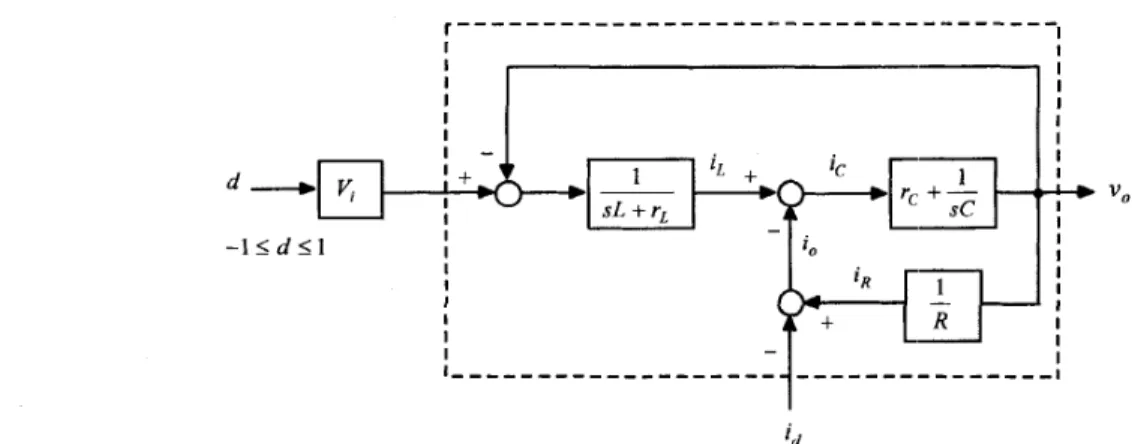
11. DYNAMIC MODEL OF THE PWM INVERTER Fig. 2 shows a PWM inverter used in an UPS system together with its output filter and load resistance. The full-
ld
bridge inverter, LC filter, and load are considered as the plant to be controlled. The voltage source vi serves as the dc bank and supplies power to the load through the full-bridge inverter. The current source i d emulates the disturbance incurred by load variation. The resistor
r c
is the equivalent series resistor(ESR) of the capacitor, while the resistor r~ is the ESR of the inductor. Owing to the existence of the four switching devices, the PWM inverter illustrated in Fig. 2 is a nonlinear system by nature. State-space averaging and linearization technique has been used to model the switching regulators as linear systems, provided that the natural frequency and modulation frequency are sufficiently low with respect to the switching frequency. In our application of UPS, the switching frequency is chosen as tens of kilohertz, which is much higher than the modulation and natural frequencies of the PWM inverter system.
A . Continuous Model of the PWM Inverter
For the ease of design, it is reasonable to assume that the dc bank voltage keeps constant for all time. Following the above assumption and the state-space averaging technique, we can get the small-signal model of the concerned PWM inverter system as
+ T L
)
i L - - h ( R : r ~ ) ' ~ ~JUNG AND TZOU: DISCRETE SLIDING-MODE CONTROL OF A PWM INVERTER 569
id
Fig. 3. The block diagram representation of the linearized PWM inverter system.
1 R
+ - - -
C R + r c i d 'where d denotes the duty ratio of switching. The block diagram representation of the system (1) is shown in Fig. 3. It provides a more detailed insight into how all the variables relate to each other.
In practice, the ESR of the filter capacitor is so small that it has little effect on the mathematical model. If we neglect the ESR of the filter capacitor, the system (1) can be further reduced to the commonly used form as
where
z
= [ i L v,]T, U =K d ,
y = v,c = [O 11
B. Discrete Model of the PWM Inverter
Sampling frequency is the first issue in deriving the discrete model of the concerned system. The selection of the best sampling frequency is a compromise between performance and cost. The best choice of sampling rate is the slowest frequency that meets all the essential requirements. The previous research reported that a digital control system will be more sensitive to errors if the sampling frequency is less than twice the dominant resonance of the open loop dynamics [17]. For the PWM inverter used in an UPS, the LC filter at output port forms the dominant resonance of the system. A rule of thumb for choosing the sampling frequency that gives reasonably smooth time response is
(3)
f s
f r - 5 5 - < 4 4 0
where f s is the sarnpling frequency and
Once the sampling, rate has been determined, the discrete counterpart of the system ( 2 ) can be obtained as
where
AT
@ = e
I'
=(AT
eAs dr) bf
=(
AT
eAs dr) hand T is the sampling period of the digital controller. Here, we have assumed that the values of U and id are virtually constant during each sampling period. As far as the PWM inverter is concerned, there are still several uncertainties that cannot be well modeled.
1) The real values of capacitance and inductance must be measured at their operating points, but it is nearly impossible in practice. Thus, only the approximated nominal values can be measured.
2 ) The load of ithe PWM inverter is not fixed. There are many types of loads may be connected to the output port of the PWM inverter.
3) The characteristics of the switching devices are not ideal in practice.
In order to generate sinusoidal output voltage with low distortion, a poweirful controller must be designed for the closed-loop regulation of the PWM inverter. In this paper, a
discrete feedforward sliding-mode control scheme is proposed to enhance the robustness of the PWM inverter suffering from load variation.
570 IEEE TRANSACTIONS ON POWER ELECTRONICS, VOL. 11, NO. 4, JULY 1996
,
,I
feedforward1
f',
controllerI -
sensor UFig. 4. The proposed discrete feedforward sliding-mode control scheme.
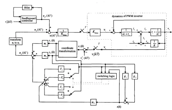
111. DISCRETE FEEDFORWARD SLIDING MODE CONTROL Fig. 4 shows the proposed discrete feedforward sliding- mode control scheme. Since the reference signal in our appli- cation is given in advance, a feedforward controller is added to improve the tracking performance of the PWM inverter. The analysis of the proposed control scheme will be presented in the following subsections.
A. Feedforward Controller
Consider the PWM inverter system
(4),
which can be written aswhere
U ( k ) = U f ( k )
+
u s ( k ) .The control force is composed of two parts: a feedforward control force ( u f ) and
a
sliding-mode control force (us). The reference command of U, and i~ are given as U,* and iT;. SinceU: and
iT;
should also satisfy(3,
we haveHere, we have assumed that the system (5) is free of distur- bance (i.e., id = 0) and uf can then be derived from (6) by eliminating iT; as 1 71 U f ( k ) = -b,*(k
+
1) - (411+
422).,*(k) - ( 4 1 2 4 2 1 - 4 1 1 4 2 2 ) U ; ( k - 1) - ( 4 1 2 7 2 - 4 2 2 7 1 ) U f ( k -I)].
(7) In fact, (6) is merely the inverse dynamics of (5) with load disturbance being disregarded. To ensure the stability of the inverse dynamics, we have assumed that the original system(5) is of minimum phase. That is, all the poles and zeros of (5) must fall within the unit circle of z-plane. By subtracting
(6) from (5), we get the error dynamics as
e l ( k
+
1) = 4 l l e l ( k )+
4 1 2 e 2 ( k )+
7l.s(k)+
f l i d ( k )e z ( k
+
1) = dzlel ( I C )+
dzzez(k)+
r2u,(k)+
f d k ) . (8)where
Q ( k ) =.o(k) -
4 ( k )
e z ( k ) = i L ( k ) - iT;(k).Since the desired state of el and e2 are both zero, the original problem of tracking a specific function has been reduced to the problem of regulating all the states to zero at this stage. It follows from (5) and (8) that the feedforward controller generates most of the control force while the sliding-mode controller only has to compensate for the error induced by load variation. The stress of the sliding-mode controller can thus be reduced due to the feedforward compensation.
The state e2 requires the command iT;, which is hard to
derive explicitly. If the load is assumed to be resistive, it can be approximated as
where
U0
Re
= 72 0
and
Re
is the estimated load resistance. In practice, however, it is difficult to measure the ratio between the output voltage and the load current because of the noisy feedback signals. Therefore, we transform the system (8) into another form in which only the output voltage is sensed as feedback. B. Coordinate Transformationcurrent ( i i ) , we define a new pair of state variables as In order to avoid estimating the command of inductor
The system (S), which has been compensated by the proposed feedforward controller, can then be rewritten as
z ( k
+
1) 4 1 2 4 2 1 - 4 1 1 4 2 2+
411
+
4 2 2 4 1 1 4 2 2 -4 & q
= L 1 2 4 2 1 - 4 1 1 4 2 2+
411
+
4 2 2 - 1 4 1 1 4 2 2 - 4 1 2 4 2 1I
+ [
Y l U S ( k )+
( 4 1 2 7 2 - 422Y1)US(k - 1) .Z(k) 71us(k)+
(412.72 - 4 2 2 7 l ) U S ( k - 1)JUNb ANU I L U U U l X U l k ! bL1UINti-MODh CONTROL OF A PWM INVERTER 57 1
filter inductor L filter capacitor C
Fig. 5. Block diagram representation of the proposed DFSMC scheme.
3.56mH 9.92 pF where load resistance sampling frequency @z
1
=[4
1 2 4 2 1 - 4 1 1 4 2 2+
4 1 1+
4 2 2 - 1 4 1 1 4 2 2 - 4 1 2 4 2 1 4 1 2 4 2 1 - 4 1 1 4 2 2+
4 1 1+
4 2 2 4 1 1 4 2 2 = 4 1 2 4 2 1 ~ ~~ 50 L2 10 kHz bz =[;I
PO1
flid(k)+
(412f2 - 422fl)id(k - 1) lZd(k)+
(412f2 - 422fl)id(k - 1)u z ( k )
= 7 1 u s ( k )+
( 4 1 2 7 2 - 42271)us(k - 1). d = [ , .It can be seen from (10) that only the output voltage needs to be measured as feedback after coordinate transformation.
Since the values of 4z3’s are dependent on the load resistor,
the system (1 1) suffers from parametric variation as the load changes. Therefore, the remaining control law U , must be designed such that the system (11) is robust against plant uncertainty. It should be noted that U , is a pseudo variable, the control force really applied to the PWM inverter is given by
0.28
The sliding-mode control strategy is adopted here to design U ,
so that the whole system can be robust against load variation. Since all the states of the system (11) are supposed to be driven to zero by U,, the discrete sliding-mode control theory developed for the regulation of servo systems can be used hereafter.
TABLE I
NOMINAL VALUES OF THE RELEVANT PARAMETERS
DC-BUS V,
I
250VESR rL
1
0 . 4 0I
O RESR rc
TABLE I1
PARAMETERS OF SLIDING-MODE CONTROLLER
in,
1
0.251I
C. Discrete Sliding-Mode Controller Considering Load Disturbance
The objective of the sliding-mode controller is to force the state trajectory of the controlled system to slide over a predesigned sliding curve in phase plane. Consider the system ( l l ) , which has been compensated by the proposed feedforward controller, the states z l ( k ) and z z ( k ) are to be
512 IEEE TRANSACTIONS ON POWER ELECTRONICS, VOL. 11, NO. 4, JULY 1996
Volt
200 7 1---, Amp 10
1
fiF
output vokage :'550 0 -50 -100 - 1 50 2.5 0 - 2 . 5 -5 -7.5 -200
L
0.02 0.025 , , - l o 0.03 (sec) Volt /' 200 ' 1 5 0 L 1fh
sliding mode control
-200 I 0.02 0.025 0.03 (sec) (a) (c) 22 40 - 20 - 0.02 0.025 0.03 (sec) -20 0 (b) (dl Fig 6
control force and sliding-hode control force (d) State trajectory in the phase plane
Simulation results of the proposed DFSMC scheme (a) Output voltage and load current (b) Value of the sliding function s ( k ) (c) Feedforward
driven to zero by the control force U,. The corresponding sliding curve is defined as
s ( k ) = g'+) = glzl(k)
+
, 9 2 z 2 ( k ) . (13) The so-called equibalent control law can be derived by disre- garding the disturbance and setting s ( k+
1) = s ( k ) [13]-1
U e q = -gT(Qz -
qzo)
a!01 = g T b , (14)
The vector g should be designed such that the closed-loop system controlled by ueq has all its eigenvalues inside the unit circle in z-plane except the trivial one A2 = 1. The criterion for choosing g will be described in the next subsection. Being unlike the conventional analog sliding-mode controller, the discrete sliding-mode controller is designed to satisfy the following reaching condition [ 141:
I 4 k
+
111<
l4k)l. (15) The inequality (15) shows that the properly designed discrete sliding-mode control law will drive the state trajectory toward the sliding curve s ( k ) = 0 step by step. According to (15), the discrete sliding-mode control law can be designed as follows [13]:The feedback gains cp1 and cpz are determined as follows 1131:
9% =
{
0 if-6,
5
a z 7 ( k ) s ( k )5 6,
i = 1 , 2 (17)Fo
if a z , ( k ) s ( k )<
-6,
-Fo if a z , ( k ) s ( k )>
6, wherer 2
1
L" - d = max lgTdl.The switching gains defined in (17) are somewhat different from those proposed in 1131. The last term of 6, is used to deal with the disturbance incurred by load variation. If
2
= 0, the control law degenerates into that proposed by 1131. The factorcpo must be chosen such that 0
<
p<
1. To make sure that the control law (17) exists, the following condition should hold:JUNG AND TZOU: DISCRETE SLIDING-MODE CONTROL OF A PWM INVERTER
Together with the fact that
Fo
is positive and the assumption513
Volt
that Q is
O<Fo<
positive, we have
Inequality (20) comes from the fact that the right-hand side of (19) is positive. Since
2
is the term corresponding to the amplitude of load disturbance, it should also be positive. Therefore, we can derive the bound of load disturbance from (20) as follows:0
i d <
-(1+ p ) l s ( k ) l+
4 1+
P)21s(k.)12+
4(1 - p)lazz(k)s(k)li = 1 , 2 . (21)
It can be seen from (21) that the condition (18) may be violated when the state trajectory get close to the sliding curve
s ( k ) = 0. This may cause the state trajectory to depart away from that curve. However, since
d
is bounded in practice, the inequality (21) will be eventually satisfied and the sliding- mode controller works again as the state trajectory is far enough from the sliding curve. Finally, the state trajectory will be kept within a circle around the origin of the phase plane. The higher the amplitude of the load disturbance is, the larger the radius of the circle is. Fig. 5 illustrates the block diagram representation of the PWM inverter system controlled by the proposed DFSMC scheme.D. Selection of Sliding Curve
In this subsection, the sliding curve of the discrete sliding- mode controller is designed through the technique of opti- mization with quadratic cost function. Consider the following system:
which is almost the same as (11) except that the disturbance
is disregarded. To facilitate further analysis, a transformation is defined as
w ( k ) = M z ( k ) (23) where M is an invertible matrix with the following property:
M [ : ] =
[:I.
With this transformation, the system (22) can be converted into the following canonical form:
- 1 0 0 : , , , ,
__
-150 -200 0 0 01 0.02 0.03 0.04 0.05 0.06 0.07 0.08 0.09 0.1 (sec) (a) 10 20 30 40 50 60 Frequency (Hz) (b)Fig. 7. (a) Output voltage of the PWM inverter (10 Hz) by using the method proposed in [16]. (b) Comparison of output distortion between the DFSMC scheme and the DSMC scheme reported in [16].
The sliding curve after transformation becomes
s ( k ) = g T z ( k ) = gTM-lw(K) g T w ( k )
= g l w I ( k )
+
62W2(k) = 0. (26) From the first equation of (25), we haveThe equations (26) and (27) constitute the dynamics of the controlled system subject to the sliding curve. We can view (27) as another new system with state tu1 ( k ) and pseudo input
w ~ ( k ) . The cost function for optimization is selected as (28)
J(w) = qwl@y
+
rw2(rq2where q and T are positive real numbers. The sliding curve
514 IEEE TRANSACTIONS ON POWER ELECTRONICS, VOL. 11, NO. 4, JULY 1996
I / I I / I I 1 1 -
+
. - -
voltage
digital controller (DSP TMS320C14) converter
Fig. 8. Hardware architecture of experimental setting.
trajectory reaches the curve s ( k ) = 0. It follows from the model of the PWM inverter system can be derived as
optimal control theory [I81 that the pseudo input should have
the following form: p ( k
+
1)] =[
0.6969 8.65451i ~ ( k
+
1) -0.0241 0.8603 i ~ ( k )w 2 ( k ) = -nw1(k) (29) 0.1289 8 7061 ,
+ 10.02671
4')
+ 1-0.12901'
d
'
)
L A L A
The ESR of the capacitor has been neglected for the ease of design.
A. Feedfonvard Controller
Disregarding the load disturbance in (34), the PWM inverter system has all its poles and zeros inside the unit circle of z-plane. The feedforward controller can thus be designed as and p satisfies the so-called discrete-time Riccati equation
p$:ll - p + ~ - p ~ z ~ 1 ~ ~ 1 2 ( . + ~ ~ ~ 1 s ) - 1 ~ ~ z 1 ~ ~ z 1 ~ = 0. (30) When the state trajectory reaches the curve S ( k ) = 0, the
equality (26) leads to
.41
w 2 ( k ) = - 7 w 1 ( k ) . 9 2
Comparing (29) with (3 I), we have
n.
(31) u f ( k ) =
7.7580~K(k
+
1) - 12.0807~,*(5)+
6.2692~,*(k - 1) - 0 . 9 3 2 5 ~ f ( k - 1).(35)
With this feedforward controller, the system (34) becomes Y ln = 2 .
If we set g2 = 1, then ijl = n. The sliding curve can be obtained as (32) [el(k
+
I ) ] =[
0.69698.65151
[el(')] e s ( k+
1) -0.0241 0.8603 e s ( k )+
r . 1 2 8 9 1[
8.70611.
0.0267 + -0.1290 Z d ( k ) (36) s ( k ) = g T z ( k ) = g T M z ( k ) = [n l]Mz(k). (33) where Owing to the inherent properties of the optimal criterion,the designed sliding curve (33) cannot only achieve better performance than the other solutions but also assure the stability of the PWM inverter system concerned.
e l ( k ) =
wo(k)
-v,*(lc)
e 2 ( k ) = i L ( k ) - i z ( k ) .The reference command of the output voltage is chosen as a 60-HZ sinusoidal wave with rms value equal to 110 V
1V. ILLUSTRATIVE EXAMPLE AND EXPERIMENTS v : ( ~ c ) = 1 1 0 J Z s i n ( 1 2 0 ~ / ~ 1 c ~ ) (37) The relevant parameters of the experimental system are
listed in Table I. The resonant frequency of the LC filter where T is the sampling period and is 100 ps in this case. is 846.9 Hz. Referring to the rule described in (3) and
the computation speed of DSP TMS320C14, we choose the sampling rate of the digital controller as 10 kHz. According to (1)-(4) and the parameters listed in Table I, the discrete-time
B. Coordinate
The system (36) can be transformed into the form with only output voltage feedback by applying the coordinate
JUNG AND TZOU: DISCRETE SLIDING-MODE CONTROL OF A PWM INVERTER .LI - ~ L - 1 _ _ 200 150 100 5 0 0 -50 -100 -1 5 0 -200 1 0 7.5 5 2.5 0 -2.5 -5 -7.5 -10 (b)
Fig. 9. Output voltage and load current under (a) resistive load variation and (b) rectifier load.
transformation defined in (10) [“‘(k
+
l ) ] =[
0.7491 0.80811 r i ( k ) ] ~ z ( k+
1) -0.2509 0.8081 ~ 2 ( k )1
0.1289uS(k)+
0 . 1 2 0 2 ~ , ( k - 1) 0.1289uS(k)+
0 . 1 2 0 2 ~ , ( k - 1) 8.7061id(k) - 8.6062id(k - 1) 8.7061id(k) - 8.6062id(k - 1) The variable U , is defined asuZ(k) = 0.1289uS(k)
+
0.1202uS(k - 1). (39)The system (38) thus becomes
The sliding-mode control force really applied to the PWM inverter is then given by
u s ( k ) = 7.7580uZ(k) - 0.9325u8(k - I ) . (41) C. Discrete Sliding-Mode Controller
To design the sliding curve, the cost function for optimiza- tion is chosen as follows:
576 IEEE TRANSACTIONS ON POWER ELECTRONICS, VOL 11, NO 4, JULY 1996
where uil and w2 are defined in (23) and the matrix M is selected as
M =
[:
;I]. (43)According to the dynamics of the PWM inverter (40) and the procedure described in the last section, the optimal sliding curve is designed as
(44)
With this sliding curve, the eigenvalues of the closed-loop system when the state is sliding on the curve are thus put at 0.382 and 1. The latter is a trivial solution due to the sliding motion. The corresponding discrete sliding-mode controller is designed through (16) and (17), and its relevant parameters are listed in Table 11.
~ ( k ) = 1.2361zl(k)
+
0 . 7 6 3 9 ~ 2 ( k ) .D.
Simulation ResultsFig. 6(a) shows the simulation results of the output voltage and load current under phase-controlled load. The output voltage is robust against load variation and does follow the reference command with tolerable tracking error. Fig. 6(b) de- picts the value of the sliding function s ( k ) . Fig. 6(c) illustrates both the feedforward and the sliding-mode control forces. The latter works only when the load deviates from its nominal value. Fig. 6(d) shows the state trajectory of the controlled PWM inverter system. It can be seen from the result that the designed sliding-mode controller can drive the state trajectory toward the sliding curve after load transition. The trajectory does reach the designed sliding curve and then approaches the origin along that curve. At last, the trajectory is confined within a circle around the origin. This verifies our explanation about the bound on load disturbance.
Fig. 7(a) shows the output voltage of the same PWM inverter (10 Hz) by using the method proposed in [16]. The waveform is more oscillatory than the one shown in Fig. 6.
Fig. 7(b) illustrates a comparison between the DFSMC scheme proposed in this paper and the DSMC scheme reported in [16].
The figure depicts the harmonic distortion of the output voltage at different frequencies under rated resistive load. The result indicates that the proposed DFSMC scheme has better steady state characteristics than the DSMC scheme.
E. Experimental Results
A 1-kVA PWM inverter based on IGBT (GT25Q101) was implemented to verify the proposed DFSMC scheme. Fig. 8 shows the hardware architecture of the experimental setting. A
high-speed digital signal processor TMS320C 14, produced by Texas Instruments Inc., is used as the digital controller. The reference signal is a sampled sinusoidal wave stored in the program memory. Since TMS320C14 is capable of generating PWM signal, no extra modulation circuit is included in the constructed system. The switching frequency of the PWM gating signal is 20 kHz, and 10 bits of PWM resolution can be obtained at this frequency. The DSP controls the switches of the PWM inverter directly so that the output voltage can
track the reference command at every sampling instant. The sampling action is realized through software interrupt that is generated by a built-in programmable timer every 100 ps.
Fig. 9(a) shows the experimental results of the output volt- age and load current under resistive load variation. The output voltage can still track the reference command in an asymptotic manner after load transition. The resemblance between the simulation and the experiment verifies the theoretical analysis
of the proposed DFSMC scheme. Fig. 9(b) depicts the exper- imental results under rectifier load. It can be seen from these results that the proposed DFSMC scheme can still work even under rough load condition.
V. CONCLUSION
In this paper, a discrete feedforward sliding-mode control scheme is developed for the closed-loop regulation of the PWM inverter used in an UPS. The proposed scheme combines a linear feedforward controller with a nonlinear sliding-mode controller. The feedforward controller generates most of the control force while the sliding-mode controller only compen- sates the output voltage for the error incurred by load variation. Moreover, we also propose a coordinate transformation such that only the output voltage of the PWM inverter needs to be measured as feedback. The sliding curve of the sliding- mode controller is designed through optimal criterion so that the behavior of the controlled PWM inverter is optimized with respect to the selected cost function. In addition, the effect of
load disturbance has been taken into the design consideration of the sliding-mode controller. A DSP-based digital-controlled PWM inverter prototype has been constructed and tested. A
high-performance DSP TMS320C14 is adopted as the main processor. The experimental results show good agreement with the theoretical analysis done in this paper. Since the feedforward controller works mildly in steady state and the sliding-mode controller is robust against load variation, the output voltage of the controlled PWM inverter is much more smooth than that reported in the previous study while the same robustness can still be achieved.
REFERENCES
D. C. Griffith, Uninterruptible Power Supplies: Power Conditioners f o r
Crirical Equipment.
B. D. Bedford and R. G. Hoft, Principles of Inverter Circuits. New
New York: Marcel Defier, 1989.
. I
York: Wiley, 1964.
I. J. Pitel. S. N. Talukdar, and P. Wood, “Characterization of uro- grammed waveform pulse width modulation,” IEEE Trans. Ind. Appli-
cat., vol. 16, no. 5, pp. 707-715, 1980.
Y. Sekino, M. Shibata, and N. Hotaka, “Inverter output voltage wave- form closed-loop control technique,” in ZEEE INTELEC Con$ Rec.,
1983, pp. 205-212.
A . Kawz“rd and R. G. Hoft, “Instantaneous feedback controlled PWM inverter with adaptive hysteresis,” IEEE Trans. lnd. Applicat., vol. 20,
no. 4, pp. 769-775, 1984.
K. P. Gokhale, A. Kawamura, and R. G. Hoft, “Dead beat microproces- sor control of PWM inverter for sinusoidal output waveform synthesis,” in IEEE PESC Con$ Rec., 1985, pp. 28-36.
T. Kawabata, Y. Shikano, and S. Higashino, “Chargeless UPS us-
ing multi-functional BIMOS inverter-Sinusoidal voltage waveform inverter with current minor loop,” in IEEE IAS Ann. Meet., 1986, pp.
5 13-520.
V. 1. Utkin, “Variable structure systems with sliding modes,” IEEE
JUNG AND TZOU: DISCRETE SLIDING-MODE CONTROL OF A PWM INVERTER 511
1171 1181
J.-J. E. Slotine and W. Li, Applied Nonlinear Control. Englewood Cliffs, NJ: Prentice-Hall, 1991.
M. Carpita, M. Marchesoni, M. Oberti, and L. Puglisi, “Power condi- tioning system using sliding mode control,” in ZEEE PESC Conf Rec.,
1988, pp. 626-633.
F. Boudjema, M. Boscardin, P Bidan, “VSS approach to a full bridge buck converter used for ac sine voltage generation,” in ZEEE ZECON
Con$ Rec., 1989, pp. 82-88.
K. Furuta, “Sliding mode control of a discrete system,” Systems &
Control Lett., vol. 14, no. 2, pp. 145-152, 1990.
C. Y . Chan, “Servo-systems with discrete-variable structure control,”
Systems & Control Lett., vol. 17, no. 4, pp. 321-325, 1991. W. J. Wang and G. H. Wu, “Variable structure control design on discrete- time systems from another viewpoint,” Control-Theory and Advanced
Technology, vol. 8, no. 1, pp. 1-16, Mar., 1992.
S. V. Drakunov and V. I. Utkin, “On discrete-time sliding modes,” in IFAC Nonlinear Control Systems Design-Selected Papers from the
IFAC Symp., 1989, pp. 273-278.
S. L. Jung and Y. Y. Tzou, “Sliding mode control of a closed-loop regulated PWM inverter under large load variation,” in IEEE PESC
Con$ Rec., 1993, pp. 616-622.
G. F. Franklin, J. D. Powell, and M. L. Workman, Digital Control of
Dynamic Systems.
F. L. Lewis, Applied Optimal Control and Estimation. Englewood Cliffs, NJ: Prentice-Hall, 1992.
Reading, MA: Addison-Wesley, 1990.
Shih-Liang Jung (S’96) was bom in Hsinchu, Taiwan, Republic of China, on September 15, 1969. He received B.S. degree in control engineering from National Chiao Tung University, Hsinchu, Taiwan, Republic of China, in 1991. He is now completing the Ph.D. degree in control engineering at the same university.
His research interests include variable structure systems, and DSP-based digital control techniques and their applications to power electronics systems.
Ying-Yu Tzou (S’81-M’88) was bom in Taiwan, Republic of China, on February 13, 1956. He re- ceived the B.S. and M.S. degree in control engi- neering from the National Chiao Tung University, and the Ph.D. degree in electrical engineering from the Institute of Electronics Engineering of National Chiao Tung University in 1978, 1983, and 1987, respectively.
During 1980-1981 he was with the Electronic Re- search and Service Organization (ERSO) of Industry Technology Research Institute (ITRI) as a Design Engineer in the Control System Department of the Factory Automation. During 1983-1986 he was with Microtek Automation, Inc., as a Project Manager for the development a computer numerical controller (CNC) for machine tools. He is currently an Associate Professor of the Department
o f Control Engineering of National Chiao Tung University and also serves as an industrial consultant. He was the Director o f the Institute o f Control Engineering during 1992-1994. He has authored numerous papers on power electronics, motion control, ac servo drives, parallel processing and control systems, and DSP applications in the control of power converters and motor drives.