In this article, the S parameters of the prototype were measured using a vector network analyzer (Agilent E5071B).
When the port 1 is excited and the port 2 is terminated to a 50-⍀ load, the measured and simulated S parameters of the pro-totype are shown in Figure 7. The measured impedance bandwidth, defined by ⫺10 dB return loss, reaches 630 MHz (1860–2490 MHz), which covers the UMTS band and 2.4-GHz WLAN band. Across the two bands, the isolations of the prototype are larger than 14 and 18 dB respectively. Because of the symmetric con-figuration, S22(S12), which is not given in this article, is consistent with S11(S21).
When one of the two ports is excited and the other port is terminated to a 50-⍀ load, the radiation patterns of the proposed antenna are measured in an anechoic chamber. Figures 8 and 9 show the patterns of the two monopoles at 2.05 GHz, respectively. The measured patterns at 2.44 GHz, which have not been shown in this article, have similar characteristics with those at 2.05 GHz. One can find that the measured radiation patterns of monopole 1 and 2 cover complementary space regions, so the proposed diver-sity antenna can provide pattern diverdiver-sity in a wireless communi-cation system.
In this article, the antenna efficiency is approximately calcu-lated by
⫽ 1 ⫺ 兩S11兩2⫺ 兩S21兩2 (1)
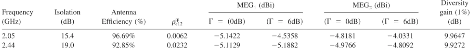
According to the method presented in [7] and the above measured results, the envelope correlation coefficiente12rp and the MEGs of the prototype are calculated and listed in Table 1. In the table, we assume that the cross-polarization discrimination⌫ ⫽ 0 dB or ⌫ ⫽ 6 dB, which are the average values in an indoor and an urban fading environment respectively, and the MEGs are proximately calculated by x-y plane pattern.
From Table 1, one can find that the received signals satisfy the conditions e12⬍0.5 and P1⬇P2( MEG1/MEG2⬍3 dB) [1]. On the basis of the conditions, the diversity gain at 1% of the cumu-lative distribution functions (CDFs) is calculated, and the results show that the high diversity gains in both bands are obtained. As a consequence, the proposed antenna has good bandwidth, isola-tion, and pattern diversity performance in wireless communication system.
5. CONCLUSION
A novel wideband diversity antenna is proposed in this article. The measured relative bandwidth, according to⫺10 dB return loss, is 29.0% (1860 –2490 MHz) with acceptable isolation over the band-width, which covers UMTS band and 2.4 GHz-WLAN band. The measured antenna patterns at 2.05 GHz are given. On the basis of the measured results, we approximately calculate the radiation efficiency, the envelope correlation coefficient, the MEGs and the diversity gain of the proposed antenna. Results show that the proposed antenna can achieve high diversity performance and is suitable for mobile handsets.
ACKNOWLEDGMENTS
This work is supported in part by the National Basic Research Program of China under Grant 2007CB310605, in part by the National High Technology Research and development Plan of China under Grant 863-2007AA01Z284, in part by the Specialized Research Fund for the Doctoral Program of Higher Education under Grant 20060003100, and in part by the Tsinghua-QUAL-COMM Associated Research Plan
REFERENCES
1. R.G. Vaughan and J.B. Andersen, Antenna diversity in mobile com-munications, IEEE Trans Veh Technol VT-36 (1987), 149 –172. 2. S.C.K. Ko and R.D. Murch, A diversity antenna for external mounting
on wireless handsets, IEEE Trans Antennas Propagat 49 (2001), 840 – 842.
3. T.-Y. Wu, S.-T, Fang, and K.-L. Wong, Printed diversity monopole antenna for WLAN operation, Electron Lett 38 (2002), 1625–1626. 4. G. Chi, L. Binhong, and D. Qi, Dual-band printed diversity antenna for
2.4/5.2-GHz WLAN application, Microwave Opt Technol Lett 45 (2005), 561–563.
5. G.A. Mavridis, J.N. Sahalos, and M.T. Chryssomallis, Spatial diversity two-branch antenna for wireless devices, Electron Lett 42 (2006). 6. S.-L.S. Yang, K.-M. Luk, Design of a wide-band L-probe patch
antenna for pattern reconfiguration or diversity applications, IEEE Trans Antennas Propagat 54 (2006), 433– 438.
7. Y. Ding, Z. Du, K. Gong, and Z. Feng, A novel dual-band printed diversity antenna for mobile terminals, IEEE Trans Antennas Propagat 55 (2007), 2088 –2096.
8. S.C.K. Ko and R.D. Murch, Compact integrated diversity antenna for wireless communications, IEEE Trans Antennas Propagat 49 (2001), 954 –960.
9. W.C. Lee, Mobile communications engineering, 2nd ed., McGraw-Hill, New York, 1998, pp. 291–335
10. Ansoft Corporation HFSS [Online]: Available:http://www.ansoft.com/ products/hf/hfss.
© 2008 Wiley Periodicals, Inc.
A CPW-FED TWO-ARM SPIRAL SLOT
ANTENNA
Chien-Jen Wang1and Jin-Wei Wu2
1Department of Electronics Engineering, National University of
Tainan, Tainan, Taiwan; Corresponding author: [email protected]
2Department of Communication Engineering, National Chiao-Tung
University, Hsinchu, Taiwan
Received 7 May 2008
ABSTRACT: A wideband coplanar waveguide (CPW)-fed two-arm
spi-ral slot antenna without a balun circuit is presented in this article. Phase progressions at arm ports are realized through the coplanar waveguide excitations. A detailed characterization of all antenna com-ponents and parameters is provided along with guidelines and
recom-TABLE 1 Performance of the Proposed Diversity Antenna
Frequency (GHz) Isolation (dB) Antenna Efficiency (%) e12 rp
MEG1(dBi) MEG2(dBi) Diversity
gain (1%) (dB)
⌫ ⫽ 共0dB兲 共⌫ ⫽ 6dB兲 共⌫ ⫽ 0dB兲 共⌫ ⫽ 6dB兲
2.05 15.4 96.69% 0.0062 ⫺5.1422 ⫺4.5358 ⫺4.8181 ⫺4.0331 9.9647
2.44 19.0 92.85% 0.0232 ⫺5.1129 ⫺5.1882 ⫺4.9766 ⫺4.8092 9.9272
mendations for broad bandwidth and small reflection. Variations of the impedance matching due to the turn numbers, the ground width sepa-rated between two neighboring turns and the slot width are tested and studied. The measured impedance bandwidth of a S11ⱕ 10 dB ranges
from 1.63 to 8 GHz and covers most of the commercial wireless commu-nication systems, such as DCS, PCS, IMT-2000, WLAN, Bluetooth, and HIPERLAN. © 2008 Wiley Periodicals, Inc. Microwave Opt Technol Lett 51: 222–225, 2009; Published online in Wiley InterScience (www. interscience.wiley.com). DOI 10.1002/mop.23947
Key words: two-arm spiral slot antenna; balun; Archimedean spiral 1. INTRODUCTION
Conventional Archimedean spiral antennas have the advantages of circular polarization, easy impedance matching, superior radiation efficiency, and possession of ultra-wideband characteristics [1– 4]. Generally, two-arm Archimedean spiral antennas are fed from the outer by the balun that the currents are of equal amplitude and with 180° out of phase [5]. But, the wideband balun circuit of equal amplitude and 180° phase difference were designed with difficulty and the total antenna size was increased, whereas the balun circuit was embedded. Because of the advantages of low radiation loss, less dispersion in comparison with a microstrip feed and easy combination with of MIC/MMIC modules for the design of active-integrated antennas, the coplanar waveguide (CPW)-fed slot
an-tennas have attracted more attention recently. In this article, the new design of a CPW-fed two-arm spiral slot antenna is shown. Because of the out-of-phase equivalent magnetic current flowing in the CPW transmission line, the phase difference of 180° can be achieved without any balun circuit. The positive and negative signals split from the feeding line are injected into the two-arm spiral slot antenna. A comparative study is carried out to exhibit the reflection coefficient versus the geometrical dimensions of the spiral slot, targeting the construction of a wideband antenna. The
rmax b L feeding network feeding slot X Y Z W S h ground substrate W
Figure 1 CPW-fed two-arm spiral slot antenna
-40 -30 -20 -10 0 1 2 3 4 5 6 7 8 Frequency (GHz) Re fl ec ti on co ffi ci en t (dB ) turn=3 turn=4 turn=5
Figure 2 Reflection coefficients of the antenna for different turn num-bers. [Color figure can be viewed in the online issue, which is available at www.interscience.wiley.com] -40 -30 -20 -10 0 1 2 3 4 5 6 7 8 Frequency (GHz) R ef lect io n cof ficien t (d B ) W=0.7mm W=1.2mm W=2.2mm
Figure 3 Reflection coefficient for different ground width separation w between two neighboring turns. [Color figure can be viewed in the online issue, which is available at www.interscience.wiley.com]
-40 -30 -20 -10 0 1 2 3 4 5 6 7 8 Frequency (GHz) R ef lect io n cof fi cien t (d B) S=0.4mm S=0.6mm S=1.0mm
Figure 4 Reflection coefficient for different spiral slot widths of the spiral slot antennas. [Color figure can be viewed in the online issue, which is available at www.interscience.wiley.com] -40 -30 -20 -10 0 1 2 3 4 5 6 7 8 Freque ncy (GHz) R ef le cti o n co effi ci en t (d B ) Sim ulation Measurement
Figure 5 Comparison of the simulated and measured reflection coeffi-cients of the proposed antenna. [Color figure can be viewed in the online issue, which is available at www.interscience.wiley.com]
0 45 90 135 180 225 270 315 -50 -40 -30 -20 -10 0 E-Plane (dB) Cross Co
1.65GHz E-plane
0 45 90 135 180 225 270 315 -50 -40 -30 -20 -10 0 H-Plane (dB) Cross Co1.65GHz H-plane
0 45 90 135 180 225 270 315 -50 -40 -30 -20 -10 0 E-Plane (dB) Cross Co3.70GHz E-plane
0 45 90 135 180 225 270 315 -50 -40 -30 -20 -10 0 H-Plane (dB) Cross Co3.70GHz H-plane
0 45 90 135 180 225 270 315 -50 -40 -30 -20 -10 0 E-Plane (dB) Cross Co5.80GHz E-plane
0 45 90 135 180 225 270 315 -50 -40 -30 -20 -10 0 H-Plane (dB) Cross Co5.80GHz H-plane
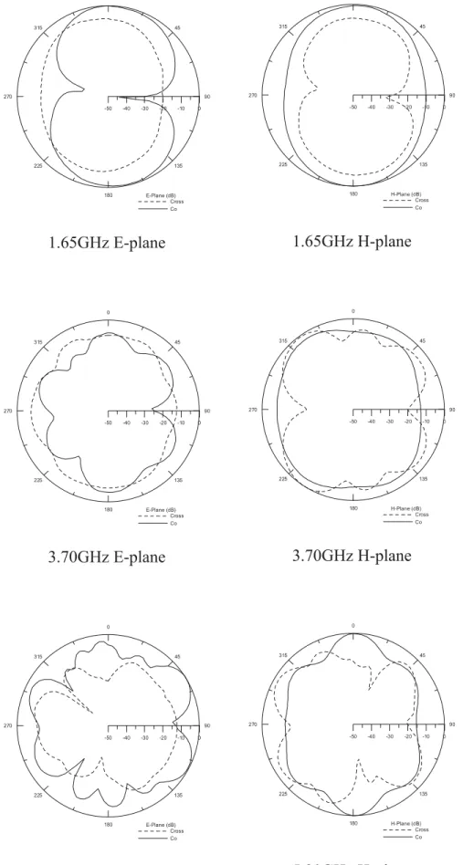
Figure 6 Measured radiation patterns of the proposed antenna
measured results of the reflection coefficients show good agree-ment with the simulated results.
2. ANTENNA DESIGN
In our work, the CPW-fed two-arm spiral slot antenna was de-signed and fabricated on high-frequency FR4 substrate, with a dielectric constant of 4.4 and the substrate thickness of 1.6 mm.
Figure 1 presents a schematic diagram of the proposed CPW-fed two-arm spiral slot antenna. The feeding structure and the spiral radiator were designed on the top plane of the substrate so that fabrication of the circuit and position alignment could be simplified. Both the out-of-phase slots of the CPW transmission line are fed into the spiral slot antenna. The angles of two arc slot lines at the feeding network are modified to obtain better imped-ance matching condition. Design concepts of the Archimedean spiral antenna were employed in our experiment to derive the radius for the CPW-fed two-arm spiral slot antenna. The empirical formula shown in Eq. (1) was used to determine the initial resonant frequency of the proposed antenna.
L⫽ 2rmax, (1)
whereLis the wavelength at the initial resonant frequency of the antenna and rmaxis the radius of the first outer slot.
The radius rmaxof 34 mm for the proposed spiral slot antenna was determined. The investigations of the geometrical parameters, including the turn number, ground width w separated between two neighboring turns, and slot width, have been achieved to derive the lower reflection coefficient for the proposed CPW-fed spiral slot antenna.
3. RESULTS
Figure 2 shows the dependence of the measured reflection coeffi-cients on the turn number with the fixed ground width (w⫽ 2.2 mm) separated between two neighboring turns and the slot width s of 0.6 mm. From the results, as the turn number increased, the initial resonant frequency of the spiral slot antenna was lowered. In addition, the impedance matching condition at the lower resonant band improved. Consequently, one rule for designing CPW-fed spiral slot antennas that can be derived from our study is that the number of turns should be increased as much as possible when the antenna area is fixed. Figure 3 shows the variations of the operat-ing frequency on the reflection coefficients for different ground width separation w between two neighboring turns with the fixed spiral slot width (s⫽ 0.6 mm) and five turns. It is clearly found that the reflection coefficients were lowered with increasing the ground width w. The reason may be that the characteristic imped-ance of the CPW transmission line was decreased as increasing the ground width w. The comparison of the measured reflection coef-ficient for different spiral slot widths of the antenna is shown in Figure 4, when the ground width w and the turn numbers are fixed by 2.2 mm and 5. As seen in the figure, the initial resonant frequency was decreased, as the spiral slot width decreased. How-ever, the magnitude of the reflection coefficient at some frequency bands increased. In our work, s⫽ 0.6 mm was chosen to obtain the better characteristics of impedance bandwidth.
Figure 5 illustrates the comparison of the simulated and mea-sured reflection coefficients of the proposed CPW-fed two-arm spiral slot antenna with five turns, w⫽ 2.2 mm and s ⫽ 0.6 mm. The measured initial resonant frequency of the proposed spiral slot antenna was 1.63 GHz. From the results, the impedance bandwidth of the proposed antenna covered most of the commercial wireless communication systems. The simulated and measured results agree
well. Figure 6 presents the measured radiation patterns of the CPW-fed two-arm spiral slot antenna at 1.65, 3.70, and 5.80 GHz. The power intensity of the cross-polarization radiations of the antenna was similar to that of the copolarization radiations. This phenomenon may be attributed to the enhancement of the surface wave because of the CPW structure and the spiral radiation aper-ture. As observed in the radiation patterns, the higher order modes were excited at higher operating frequencies in the experiments. The measured antenna gain in the broadside direction at 1.75 GHz was 2.23 dBi.
4. CONCLUSION
The novel CPW-fed two-arm spiral slot antenna has been proposed in the paper. In our design, the balun circuit is not used such that the antenna area can be miniaturized. The design rules of the proposed antenna have been experimentally derived by changing the spiral slot width, ground width between two neighboring turns and turn numbers. The measured results show that the antenna has wideband characteristics and acceptable radiation patterns.
REFERENCES
1. W.L. Curtis, Spiral antennas, IRE Trans Antennas Propag AP-8 (1960), 298 –306.
2. E. Gschwendtner, D. Lo¨ffler, and W. Wiesbeck, Spiral antenna with external feeding for planar applications, In the Proceedings of IEEE Africon, South Africa, Oct. 1999, pp. 1011–1014.
3. B. Liu and A.M. Ferendeci, Broadband slotted spiral antennas with thin dielectric substrates, In the Proceedings of IEEE Radio and Wireless Conference, Aug. 2002, pp. 59 – 62.
4. C.J. Wang and D.F. Hsu, Studies of the novel CPW-fed spiral slot antenna, IEEE Antennas Wireless Propag Lett 3, (2004), 186 –188. 5. T.H. Liu, W.X. Zhang, M. Zhang, and K.F. Tsang, Low profile spiral
antenna with PBG substrate, Electron Lett 36 (2000), 779 –780. © 2008 Wiley Periodicals, Inc.
MICROWAVE MULTI-LEVEL BAND-PASS
FILTER USING DISCRETE-TIME
YULE-WALKER METHOD
Ching-Wen Hsue,1Jer-Wei Hsu,1Yen-Jen Chen,1and Kuo-Lung Chen2
1Department of Electronic Engineering, National Taiwan University of
Science and Technology, 43 Keelung Road , Section 4, Taipei, Taiwan, Republic of China; Corresponding author:
2National Communications Commission, 6F No. 50, Sec. 1, Ren-Ai
Rd., Taipei, Taiwan, Republic of China
Received 15 May 2008
ABSTRACT: The modified Yule-Walker scheme is employed to define
arbitrary transmission scattering parameter of a multiple-level band-pass filter in the discrete-time domain. Equal-length microstrips includ-ing sinclud-ingle- and double-section stubs are used to implement the multiple-level band-pass filter. Experimental results are presented to illustrate the validity of this design method. © 2008 Wiley Periodicals, Inc. Microwave Opt Technol Lett 51: 225–229, 2009; Published online in Wiley InterScience (www.interscience.wiley.com). DOI 10.1002/mop. 24006
Key words: Yule-Walker scheme; multiple-level filter; Z domain
![Figure 2 Reflection coefficients of the antenna for different turn num- num-bers. [Color figure can be viewed in the online issue, which is available at www.interscience.wiley.com] -40-30-20-10 0 1 2 3 4 5 6 7 8Frequency (GHz)Reflectioncofficient(dB)W=0.7mmW=](https://thumb-ap.123doks.com/thumbv2/9libinfo/7534035.120169/2.918.84.444.481.765/figure-reflection-coefficients-different-available-interscience-frequency-reflectioncofficient.webp)