國
立
交
通
大
學
土木工程研究所
碩
士
論
文
虛擬實驗室之抗壓實驗
C
ompressive Strength Experiment in Virtual Material
Laboratory
研 究 生:潘天恩
指導教授:林昌佑 博士
虛擬實驗室之抗壓實驗
C
ompressive Strength Experiment in Virtual
Material Laboratory
研 究 生:潘天恩 Student:Pun Tin Ian
指導教授:林昌佑博士 Advisor:Dr. Chang-Yu Lin
國 立 交 通 大 學 土木工程學系
碩 士 論 文
A Thesis
Submitted to Department of Civil Engineering College of Engineering
National Chiao Tung University in Partial Fulfillment of the Requirements
for the Degree of Master of Science
in
Civil Engineering August 2009
Hsinchu, Taiwan, Republic of China
i
虛擬實驗室之抗壓實驗
學生: 潘天恩 指導教授: 林昌佑 博士 國文交通大學土木學系(研究所)碩士班摘要
隨著日新月異的科技發展,以及網際網路在頻寬與應用的迅速竄紅,傳 統教學中,一般文字與平面圖片無法傳達的教學內容,恰好可以經由虛擬 實境(Virtual Reality, VR)來完成並補足其缺點,特別是在工程實驗部份。 在虛擬實驗室中提供了一個全新且完整的實驗環境與操作步驟,不受時間 與空間的限制,讓學生身歷其境的隨時隨地可以上課,達到課前預習,課 後複習的完美演繹。 故此,在本研究中,針對虛擬實境的科技發展與應用作一番深入研究與 比較,並利用現在最新的 3D 軟體-3d Max, 來繪製虛擬物件與場景,最後利 用專精虛擬實境的 Virtools 來完成一個完整且功能強大的虛擬實驗室。為了 實踐虛擬功能,特別依據工程材料實驗中的混凝土抗壓實驗,帶領學生實 際體驗虛擬實驗室的優點與發展,並延伸放置網際網路之中,達到無遠弗 屆的即時教學目的。ii
Student: Pun Tin Ian Advisor: Dr. Chang-Yu Lin Department of Civil Engineering
National Chiao Tung University, Taiwan
Compressive Strength Experiment in Virtual Material Laboratory
Abstract:
With the constant progress of multimedia technology and network bandwidth, the traditional teaching environment that based on text and pictures will be integrated with media stream or virtual reality.
Visual simulation boomed out to be an essential tool in the 21st century. Slowly, VR technology has been widely proposed as a major technological advance that has potential to support for education and most importantly, it allows students to visualize abstract concepts. This research mainly illustrates the study of virtual laboratory, the difference of teaching strategies to explore the changes of students‟ concept understanding, learning motivation, computer learning motivation which influences their learning motivation and concept understanding. In this paper, the compressive strength experiment is one of the designed experiments. It integrates 3ds max, Auto CAD, Virtools to carry out a seemed-to-be-real 3D effect- Virtual Reality (VR). Through this event, students can “experience” the whole experiment procedures clearly without any space limit.
iii
Acknowledgement:
In a flake of an eye, the life in NCTU is coming to a summit; lots of remarkable memories fill my mind-Laughter, sadness, anxiety, happiness etc. No sooner, I have to step into the society where there‟s full of challenge and no more campus naivety. I really miss those moments. I sincerely feel grateful to my dear advisor, Dr. Chang-Yu Lin. He is always by my side to give me lots of supports and ideas whenever I feel helpless. Without his advices, my research will probably not be come up so fantastically. This kindness will always be carved inside my heart.
In the days of struggling with my study, my dear classmates and colleagues in the laboratories also gave me lots of support. Here, I would like to show my grace to Yi Ming who has given me lots of support, help, ideas and opinions during the whole process. This warmth always fills my heart; and also my partner, Cheh Yi. She gave me lots of help in the working procedures generously. They all bring a marvelous campus living to me
Lastly, I would like to show my high gratitude to my dearest parents. Leaving home for almost 6 years, they didn‟t utter a word of such a long departure despite of their longing mind of homing. Instead, they showed me only limitless support. Through the success of my research, I would like to share this happiness with them.
I sincerely hope that happiness and success always fill the heart of every one of them.
iv
Table of Content
摘要 ... i Abstract:... ii Acknowledgement: ... iii Table of Content... iv List of Figures………...vi Chapter 1 Preface ... 1 1.1 Motivation ... 1 1.2 Purpose ... 21.3 Method and Process... 3
Chapter 2 Background and Documents Review... 5
2.1 Foundation of learning theory ... 5
2.1.1 Behaviorism [2] ... 6
2.1.2 Cognitivism [2] ... 6
2.1.3 Constructivism [2] ... 7
2.2 Computer Aided Education (CAE) [3] ... 8
2.3 Computer Aided Design (CAD) [4] ... 10
Chapter 3 Virtual Reality (VR) and tools ... 12
3.1 An introduction to Virtual Reality (VR) ... 12
3.1.1 Impact of Virtual Reality ... 14
3.1.2 The three essential factors for Virtual Reality [6] ... 16
3.1.3 Civil Engineering Problems and Solution by VR [7] ... 17
3.1.4 Program languages of Virtual Reality [8] ... 18
3.1.5 Devices of Virtual Reality [6] ... 19
v
3.2.1 Structure of 3ds Max [9] ... 22
3.3 Introduction of Virtools- the main VR production tool [10] ... 23
3.3.1 Features of Virtools [10]... 23
3.4 Application of Virtual Reality in Civil Engineering and Architecture (CAE) [12] ... 24
3.4.1 The importance of Compressive Strength Test ... 28
Chapter 4 Construction of Virtual Civil Engineering Material Laboratory ... 30
4.1 Design of the Virtual Laboratory ... 30
4.2 Construction of Scenes and equipments ... 31
4.3 Integration of the classroom with the experiment components: ... 34
4.4 Production of the Virtual Material Laboratory ... 35
4.5 Demonstration of Virtual Material Laboratory: ... 38
4.6 Evaluation of the Virtual Material Laboratory: ... 40
Chapter 5 Conclusion and Suggestion ... 43
5.1 Conclusion ... 43
5.2 Suggestion ... 45
vi
List of Figures
Fig 3.1 Head mounted display ... 49
Fig 3.2 Rumble chair ... 49
Fig 3.3 Data glove ... 50
Fig 3.4 space mouse ... 50
Fig 3.5 3D glasses ... 51
Fig 3.6 3ds Max ... 51
Fig 3.7 Virtools ... 52
Fig 3.8 Planning of Fuji International Speedway………52
Fig 3.9 A construction stage simulation of truss bridges... 53
Fig 3.10 Transportation simulation from different view points ... 53
Fig 3.11 Presentation of natural disasters ... 54
Fig 3.12 PC girder of a bridge superstructure ... 54
Fig 3.13 Bridge responses acted by an earthquake... 55
Fig 3.14 Compressive Strength experiment ... 55
Fig 4.1 Construction of the wall………...56
Fig 4.2 Excavation of the wall and attachment of the window ... 56
Fig 4.3 Sliding Door ... 57
Fig 4.4 Material Editor ... 57
Fig 4.5 Input of material from other file ... 58
Fig 4.6 Lighting effect in 3ds Max ... 58
Fig 4.7 Building up of a hollow object ... 59
Fig 4.8 The excavated part is done with the function Boolean ... 59
Fig 4.9 Conical concrete mold ... 60
Fig 4.10 Compressive strength machine ... 60
vii
Fig 4.12 Scraper for smoothing the excess mixture ... 61
Fig 4.13 The tray for the Compressive Strength Experiment ... 62
Fig 4.14 The stick for stirring the gravels mixture ... 62
Fig 4.15 The laboratory without floor... 63
Fig 4.16 The clone options for the models ... 63
Fig 4.17 The integration of the laboratory ... 64
Fig 4.18 The import of the laboratory in Virtools ... 64
Fig 4.19 Laboratory without light ... 65
Fig 4.20 Laboratory with light casting in different positions and angles ... 65
Fig 4.21 Set up of the right clicking on the mouse on the target object to show/hide the text ... 66
Fig 4.22 Set up of the detection of the clicking on targets ... 66
Fig 4.23 Set up of the color for the text ... 67
Fig 4.24 Button set up for the start of the animation ... 67
Fig 4.25 2D messaging in the animation... 68
Fig 4.26 htm format output………..68
Fig 4.27 Before entering the laboratory ... 69
Fig 4.28 Elements on the right hand side ... 69
Fig 4.29 Elements on the right bottom side ... 70
Fig 4.30 The middle part of the classroom ... 70
Fig 4.31 The right hand side of the laboratory ... 71
Fig 4.32 The right hand side of the laboratory ... 71
Fig 4.33The camera moves forward ... 72
Fig 4.34 The camera moves backward ... 72
Fig 4.35 The camera looks up ... 73
Fig 4.36 The camera looks down ... 73
Fig 4.37 The camera looks left ... 74
viii
Fig 4.4239 The control bar of the experiment selections ... 75
Fig 4.40 The list of experiments ... 75
Fig 4.41 Text description of the target object ... 76
Fig 4.42 Click on the red ball of the handle to start the animation……….76
Fig 4.43 Set up of text descriptions added for the text display ... 77
1
Chapter 1 Preface
1.1 Motivation
Through learning and education, knowledge can be lasted for generations. For civil engineering, most of the complicated techniques are based on applied force and material mechanics and its behavior. As a consequence, analyzing the behavior of different kinds of materials is of vital importance.
In the past, since computer technique has not gained its popularity, everything was just under imagination. Until today, everything has been altered. Due to the rapid growth of research and development and large amount of computer utilities, people start to gain benefits from it in lots of aspects. More and more people are immersed in the world of virtual reality, like computer games, simulation trainings etc. It does bring huge effects and charm. If this technique can be applied to educational purpose, students‟ interest towards learning and understanding can hence be highly raised.
Apparently, it had been proved that computers could help a lot in learning before the appearance of virtual reality. In the last century, most of the computer aided education was based on 2D effects only while the booming out of virtual simulation which requires 3D studio effects, did let students immersed into the “real” environment. In this way, they can not only gain knowledge efficiently, but also can control the time and scope so as to reach the optimized expectation.
2
There are some research shows that learning through virtual reality can let a student gain more than they can by just reading books. Aside from that, evidence also shows that virtual reality possesses a great potential in education. In the field of civil engineering, lots of mechanical behavior cannot be seen by naked eyes, so getting to the laboratory becomes a must. Needless to say, the most efficient way in analyzing the behavior of a material is through experiments. An experiment is a method of investigating causal relationships among variables. It is a cornerstone of the empirical approach to acquiring data about an object to be investigated and can be used to help solve practical problems and to support or negate theoretical assumptions.
1.2 Purpose
In traditional 2D education system, students can only focus on lectures or study materials but no self-experience. They can only imagine the behaviors between particles by words or arithmetic. The following shows the advantages and disadvantages of book studies.
Advantages:
1. Easily understand the contents of the lessons 2. Effectively express the contents
3. Effectively answer students‟ problems Disadvantages:
3
2. Time for understanding is too limited in class.
A series of material experiments will be demonstrated through simulation which integrates 3ds Max, Photoshop and Virtools in order to present a novel teaching system in education. In this study, one facet is to investigate the application and theory of virtual reality; another is to take advantage of those utilities to develop a simulation based on the material experiments so as to let students fully understand every process in the experiments before carrying out by their own. As a consequence, the final target will come out as a virtual laboratory which can be applied as a future teaching system for students. In this way, students can no longer just imagine how things go; instead, they can take reference on the animation before any experience will be carried out.
1.3 Method and Process
Virtual Reality (VR) is one of the most common and important computer aided tools in the 21st century. Through its visual and sensitivity interaction, it is credibly believed to bring its full potential to lots of applications in various fields. Aside from that, VR is also a basic utility for a computer aided system since it is an easy learning interface and able to transmit messages effectively.
The ways on how to make use of a computer in assisting learning has become a study for most of the scholars. Easy learning and easy using are the major criteria in understand a lesson. Learners need not spend too much time to get familiarity with the operating systems, but at the same time, they can effectively
4
attain the materials they want. The following shows the procedures of the research:
1. Information collection: In order to display a perfect laboratory simulation, related experiments procedures must first to be collected and manipulate for once.
2. Methods to display: Since the whole virtual laboratory needs to be displayed by animation effects, every step has to be equipped with the latest 3D technique. The most suitable utilities are 3D max-2009 version and Virtools. Aside from that, another element, Photoshop is added to the work.
3. Scenery production: The production is divided into 2 parts. The first one is the static elements and classroom production. The other is the experiments simulation production. Through the whole process, students can feel like immersing themselves into the “real world” and experience the “truth”.
4. Conclusion and suggestion: Through the designing procedure, we might come across to some difficulties and problems; however, through the experience, we can bring up some suggestions and opinions for a better research in the future.
5
Chapter 2 Background and Documents Review
2.1 Foundation of learning theory
In psychology and education, a common definition of learning is a process that brings together cognitive, emotional, and environmental influences and experiences for acquiring, enhancing, or making changes in one's knowledge, skills, values, and world views. Learning as a process focuses on what happens when the learning takes place. Explanations of what happens constitute learning theories. A learning theory is an attempt to describe how people and animals learn; thereby helping us understands the inherently complex process of learning. There are two chief values in learning theories. One is in providing us with vocabulary and a conceptual framework for interpreting the examples of learning that we observe. The other is in suggesting where to look for solutions to practical problems. The theories do not give us solutions, but they do direct our attention to those variables that are crucial in finding solutions.
There are three main categories or philosophical frameworks under which learning theories fall: behaviorism, cognitivism, and constructivism. Behaviorism focuses only on the objectively observable aspects of learning. Cognitive theories look beyond behavior to explain brain-based learning. And constructivism views learning as a process in which the learner actively constructs or builds new ideas or concepts.
6 2.1.1 Behaviorism [2]
Behaviorism also called the learning perspective (where any physical action is a behavior) is a philosophy of psychology based on the proposition that all things which organisms do — including acting, thinking and feeling—can and should be regarded as behaviors. The school of psychology maintains that behaviors as such can be described scientifically without recourse either to internal physiological events or to hypothetical constructs such as the mind.Behaviorism comprises the position that all theories should have observational correlates but that there are no philosophical differences between publicly observable processes (such as actions) and privately observable processes (such as thinking and feeling).
2.1.2 Cognitivism [2]
The earliest challenge to the behaviorists came in a publication in 1929 by Bode, a gestalt psychologist. He criticized behaviorists for being too dependent on overt behavior to explain learning. Gestalt psychologists proposed looking at the patterns rather than isolated events. Gestalt views of learning have been incorporated into what have come to be labeled cognitive theories. Two key assumptions underlie this cognitive approach: (1) that the memory system is an active organized processor of information and (2) that prior knowledge plays an important role in learning. Cognitive theories look beyond behavior to explain brain-based learning. Cognitivists consider how human memory works to promote learning. For example, the physiological processes of sorting and
7
encoding information and events into short term memory and long term memory are important to educators working under the cognitive theory. The major difference between gestaltists and behaviorists is the locus of control over the learning activity. For gestaltists, it lies with the individual learner; for behaviorists, it lies with the environment.
Once memory theories like the Atkinson-Shiffrin memory model and Baddeley's working memory model were established as a theoretical framework in cognitive psychology, new cognitive frameworks of learning began to emerge during the 1970s, 80s, and 90s. Today, researchers are concentrating on topics like cognitive load and information processing theory. These theories of learning are very useful as they guide instructional design. Aspects of cognitivism can be found in learning how to learn, social role acquisition, intelligence, learning, and memory as related to age.
2.1.3 Constructivism [2]
Jean Piaget suggested that through processes of accommodation and assimilation, individuals construct new knowledge from their experiences. When individuals assimilate, they incorporate the new experience into an already existing framework without changing that framework. This may occur when individuals' experiences are aligned with their internal representations of the world, but may also occur as a failure to change a faulty understanding; for example, they may not notice events, may misunderstand input from others, or may decide that an event is a fluke and is therefore unimportant as information
8
about the world. In contrast, when individuals' experiences contradict their internal representations, they may change their perceptions of the experiences to fit their internal representations. According to the theory, accommodation is the process of reframing one's mental representation of the external world to fit new experiences. Accommodation can be understood as the mechanism by which failure leads to learning: when we act on the expectation that the world operates in one way and it violates our expectations, we often fail, but by accommodating this new experience and reframing our model of the way the world works, we learn from the experience of failure, or others' failure.
It is important to note that constructivism is not a particular pedagogy. In fact, constructivism is a theory describing how learning happens, regardless of whether learners are using their experiences to understand a lecture or following the instructions for building their own knowledge. In both cases, the theory of constructivism suggests that learners construct knowledge out of their experiences. However, constructivism is often associated with pedagogic approaches that promote active learning, or learning by doing.
2.2 Computer Aided Education (CAE) [3]
The traditional education concept starts to be changed. It starts to combine the strategies concerning computer based technologies. As a result of these developments Computer Aided Education (CAE) methods came out. The goal of CAE is to develop the learning capacity of students and increase the teaching
9
productivity and effectiveness of instructors with the help of advanced computer based technology. This technology should be an integrated part in the education. It is also desirable to use this technology to develop attractive courses for distance education.
Advantages:
Using CAE methods students can state and explain the basic concepts in the subject easily and are able to participate in discussions of advanced concepts related to the subject content. With the visualization techniques computer graphics images are created and these images display the data and the mathematical relations of the interested subject for the interpretation, particularly of multidimensional cases. CAE provides also the substructure for interactively communication possibilities with international colleagues and presentation of the subject interested worldwide. One of the tools used for CAE is Visualization Techniques: Visualization is an important technique in the understanding of spatial data. Three-dimensional objects can be created and manipulated just as easily as two-dimensional plots. It is used for the teaching purposes as the use of techniques for the display of mathematical relations and photogrammetric operations. Important advantages of the visualization are interactivity and animation possibilities. A good visualization technique must provide the following feature like Portability: The visualization software and hardware used should be portable and run on all kind of computers. The visualization technique should be flexible, allowing the user to visualize the data in a customized way with a minimum amount of work due to configuration settings. The user should be able to change all the parameters of the
10
visualization process while illustrating and investigating the data. Virtual Reality is the interactive real-time-walk-through of the model.
2.3 Computer Aided Design (CAD) [4]
Computer-aided design (CAD) is the use of computer technology for the design of objects, real or virtual. However CAD often involves more than just shapes. As in the manual drafting of technical and engineering drawings, the output of CAD often must convey also symbolic information such as materials, processes, dimensions, and tolerances, according to application-specific conventions. It may be used to design curves and figures in two-dimensional ("2D") space; or curves, surfaces, or solids in three-dimensional ("3D") objects.
CAD is an important industrial art extensively used in many applications, including automotive, shipbuilding, and aerospace industries, industrial and architectural design, prosthetics, and many more. Aside from that, it is also widely used to produce computer animation for special effects in movies, advertising, technical manuals.
Computer-Aided Design is one of the many tools used by engineers and designers and is used in many ways depending on the profession of the user and the type of software in question. There are several different types of CAD. Each of these different types of CAD systems requires the operator to think differently
11
about how users will use them and they must design their virtual components in a different manner for each.
There are many producers of the lower-end 2D systems, including a number of free and open source programs. These provide an approach to the drawing process without all the fuss over scale and placement on the drawing sheet that accompanied hand drafting, since these can be adjusted as required during the creation of the final draft.
3D wireframe is basically an extension of 2D drafting. Each line has to be manually inserted into the drawing. The final product has no mass properties associated with it and cannot have features directly added to it, such as holes. The operator approaches these in a similar fashion to the 2D systems, although many 3D systems allow using the wireframe model to make the final engineering drawing views.
12
Chapter 3 Virtual Reality (VR) and tools
3.1 An introduction to Virtual Reality (VR)
By the rapid growth of technology, Virtual reality (VR) has become an emerging implement which allows a user to interact with a computer-simulated environment, whether that environment is a simulation of the real world or an imaginary world. The main points of VR are full immersion and inside participation. A simulation technology without immersing user as an insider in a simulated environment is not a VR technology. Most current virtual reality environments are primarily visual experiences, displayed either on a computer screen or through special or stereoscopic displays, but some simulations include additional sensory information, such as sound through speakers or headphones. Some advanced, haptic systems now include tactile information, generally known as force feedback, in medical and gaming applications. Users can interact with a virtual environment or a virtual artifact (VA) either through the use of standard input devices such as a keyboard and mouse, or through multimodal devices such as a wired glove, the Polhemus boom arm, and omnidirectional treadmill. The simulated environment can be similar to the real world, for example, simulations for pilot or combat training, or it can differ significantly from reality, as in VR games. In practice, it is currently very difficult to create a high-fidelity virtual reality experience, due largely to technical limitations on processing power, image resolution and communication bandwidth. However, those limitations are expected to eventually be overcome as processor, imaging
13
and data communication technologies become more powerful and cost-effective over time.
Virtual Reality is often used to describe a wide variety of applications, commonly associated with its immersive, highly visual, 3D environments. Lastly, it is introduced that VR falls into three main categories: 1) text-based, 2) desktop and 3) immersive VR. Text-based networked VR involves real-time environments described textually on the Internet where people interact by typing commands and "speak" by typing messages on their computer keyboards. This has been valuable in distance education. Desktop VR is an extension of interactive multimedia involving three-dimensional images and added to the experience of interactive multimedia without being considered immersive.
Immersive VR, involves a mixture of hardware, software and concepts that
allow the user to interact with a three dimensional computer generated "world"
Features of Virtual Reality [5]
Winn and Bricken suggested 6 features for pedagogy:
1. Students can obtain a definite direction in learning through VR
2. Since VR is an overall operation, students can fully immerse themselves in the learning environment.
3. A direct interacting model
4. Virtual Reality can guard students in learning through different computer generated presentations.
5. The system can automate some procedures so as to allow students to be more concentrate.
14
6. Students can do tracing on certain problems repeatedly to enhance the assimilation of any complicated problems.
3.1.1 Impact of Virtual Reality
In the 21st century, Virtual Reality has become an increasing interest in the potential social impact of new technologies. Virtual Reality will lead to a number of important changes in human life and activity. Virtual reality will be integrated into daily life and activity and will be used in various human ways. Techniques will be developed to influence human behavior, interpersonal communication, and cognition.
As we spend more and more time in virtual space, there will be a gradual “migration to virtual space,” resulting in important changes in economics, worldview, and culture.
The design of virtual environments may be used to extend basic human rights into virtual space, to promote human freedom and well-being, and to promote social stability as we move from one stage in socio-political development to the next.
Heritage and Archaeology [5]
The use of VR in Heritage and Archaeology has enormous potential in museum and visitor centre applications, but its use has been tempered by the difficulty in presenting a 'quick to learn' real time experience to numerous people. Many historic reconstructions tend to be in a pre-rendered format to a shared video
15
display, thus allowing more than one person to view a computer generated world, but limiting the interaction that full-scale VR can provide.
Mass media [5]
Mass media has been a great advocate and perhaps a great hindrance to its development over the years. During the research “boom” of the late 1980s into the 1990s the news media‟s prognostication on the potential of VR — and potential overexposure in publishing the predictions of anyone who had one (whether or not that person had a true perspective on the technology and its limits) — built up the expectations of the technology so high as to be impossible to achieve under the technology then or any technology to date. Entertainment media reinforced these concepts with futuristic imagery many generations beyond contemporary capabilities.
Architecture and Real Estate [5]
Architects use this technology to create virtual plan of their designed stuffs where people can walk through, feel and then decode. It‟s an accurate idea how your house will look like after completion.
16
Automobile manufacturing industry [5]
VR technology is utilized to create simulations. Clients take test drive before deciding on which model is the best for him. This can highly reduce any complains or problems after buying.
Medical [5]
Surgeons have tried using virtual reality technology to not only educate and train, but also to conduct remote surgery with the help of robotic devices.
3.1.2 The three essential factors for Virtual Reality [6]
According to the publishing “Virtual Reality Technology” by Grigore Burdea and Philippe Coffet, they raised three essential factors for virtual reality:
1. Imagination:
It has been proposed that the whole of human cognition is based upon imagination. When sense organs are stimulated, messages will be transmitted to the nervous system and produce illusion which is like imitating the real world. 2. Immersion:
Immersion is the state of consciousness where an immersant's awareness of physical self is diminished or lost by being surrounded in an engrossing total environment; often artificial. This state is frequently accompanied by spatial excess, intense focus, a distorted sense of time, and effortless action. In this way, when users are fully immersed into the virtual environment, they may highly enhance the efficiency of the work and will be benefitted a lot.
17 3. Interaction:
Interaction is a kind of action that occurs as two or more objects have an effect upon one another. The idea of a two-way effect is essential in the concept of interaction, as opposed to a one-way causal effect. Combinations of many simple interactions can lead to surprising emergent phenomena. Interaction highly applied in Virtual Reality in the 3D area. Through this features, the machine can detect the activities with humans and carry on any further communications and motions, and thus create a better working environment.
3.1.3 Civil Engineering Problems and Solution by VR [7]
Even though the computer gives us a lot of helps as mentioned above in load-acting responses, safety checks and CAD draft drawings, with civil engineering trend to complex and requirement to project contents rises, it cannot satisfy our needs sometime like a large project to require several side participants to act coordinately. The problems that met in CAE projects can be summarized as below.
・ The whole image about complex and large-scale projects cannot be easily grasped by 2D drawings or verbal description. Some table scaled-models are very limited.
・ Planned projects are frequently modified to satisfy the need of all the aspects.
・ Project management during construction becoming difficult because of complex process.
18
・ Multi-system running in city need a more feasible tool to display.
・ Landscape and environment evaluation trend toward a high level and cannot be realized only by imagining.
・Underground projects increase so that the unseen components arranging crowdedly.
3.1.4 Program languages of Virtual Reality [8]
1. VRML (Virtual Reality Modeling Language):
It is one of the network languages or a standard file format used for illustrating virtual space, especially for emphasizing the features of independent platform, augmentation, application in low brand-width network. At the time of VRML's popularity, a majority of users, both business and personal, were using slow dial-up internet access. This had the unfortunate side effect of having users wait for extended periods of time only to find a blocky, ill-lit room with distorted text hanging in seemingly random locations.
2. X3D:
X3D defines several profiles (sets of components) for various levels of capability including X3D Core, X3D Interchange, X3D Interactive, X3D CADInterchange, X3D Immersive, and X3D Full. Browser makers can define their own component extensions prior to submitting them for standardisation by the Web3D Consortium. Here are several applications, most of them being open source software, which natively parse and interpret X3D files, including the 3D
19
graphics and animations. It is also expected to be a future standard language for 3D graphics.
3. Java 3D:
Java 3D is a scene graph-based 3D application programming interface (API) for the Java platform. It runs on top of either OpenGL or Direct3D. Compared to other solutions, Java 3D is not only a wrapper around these graphics APIs, but an interface that encapsulates the graphics programming using a real, object-oriented concept. Here a scene is constructed using a scene graph that is a representation of the objects that have to be shown. This scene graph is structured as a tree containing several elements that are necessary to display the objects.
3.1.5 Devices of Virtual Reality [6]
1. Head-Mounted Display, HMD:
It is a display device, worn on the head or as part of a helmet, that has a small display optic in front of one (monocular HMD) or each eye (binocular HMD). It mainly includes: 1) microphone which is used for communication. 2) Headset for receiving signals. 3) Head-Tracking Device for tracing the users‟ own action and they can transmit any messages of their motivations, locations etc back to the computers as well. 4) LCD Screen, which is belonged to the locus system. (Fig 3.1) HMD normally applied in aviation, tactical, engineering, medical, gaming and sports.
20 2. Force Feed-Back Devices:
It is an I/O tactile device and categorized as the following: 1) Shadow Dextrous Hand:
The Shadow Dexterous Hand is an advanced robot hand system that reproduces all the movements of the human hand and provides comparable force output and sensitivity.
2) Rumble Chair:
Thundering Audio Technology creates a true Force-Feedback sensation for unmatched interactive gaming.(Fig 3.2)
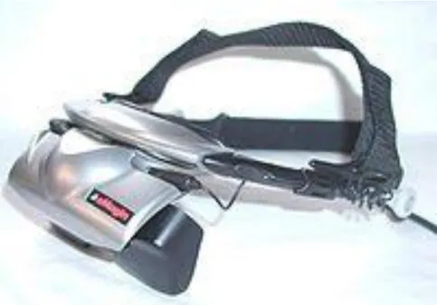
3. Data Glove:
It is a glove-like input device for virtual reality environments. Various sensor technologies are used to capture physical data such as bending of fingers. Often a motion tracker, such as a magnetic tracking device or inertial tracking device, is attached to capture the global position/rotation data of the glove. These movements are then interpreted by the software that accompanies the glove, so any movement can mean any number of things. (Fig. 3.3)
4. Space mouse:
This is a cheaper device among others. It is reformed to a 3D input device instead of the traditional 2D input technique. Users can move and rotate in the 3-dimensional space by the fingertips only. (Fig 3.4)It can also provide intuitive and precise interactive motion control of three-dimensional graphic objects in up to six degrees of freedom simultaneously.
21 5. 3D glasses:
The illusion of three dimensions on a two dimensional surface can be created by providing each eye with different visual information. Classic 3D glasses create the illusion of three dimensions when viewing specially prepared images. The classic 3D glasses have one red lens and one blue. It is made of cardboard and plastic are distributed at 3D movies. Another kind of 3D glasses uses polarized filters, with one lens polarized vertically and the other horizontally, with the two images required for stereo vision polarized the same way. Polarized 3D glasses allow for color 3D, while the red-blue lenses produce a dull black-and-white picture. (Fig. 3.5)
6. Projection VR
Projection VR permits more users with 3D glasses to get into the virtual environment at the same time. Its principle requires a projector to make projection on a large screen and users can experience the effect by wearing the 3D glasses. Most of the projection VR can be found in amazement parks, museums or 360 degree projection movies.
3.2 Introduction of Autodesk 3ds Max
3ds Max (Fig 3.6) is the third most widely-used off the shelf 3D animation program by content creation professionals. It has strong modeling capabilities, a flexible plugin architecture and a long heritage on the Microsoft Windows platform. It is mostly applied in construction, mechanical, electrical & plumbing
22
systems, process plant design and real estate, video game developers, TV commercial studios and architectural visualization studios. It is also used for movie effects and movie pre-visualization.
In addition to its modeling and animation tools, the latest version of 3ds Max also features advanced shaders such as ambient occlusion and subsurface scattering, dynamic simulation, particle systems, radiosity, normal map creation and rendering, global illumination, an intuitive and fully-customizable user interface, and its own scripting language.
In the field of architectures and civil engineering, it is also widely used. For example, Arup (A large construction company in the US) had once designed a highway and Tappan Zee Bridge which is 3.1 miles long, and the application software was 3ds Max. They claimed that this utility provided a high 3D resolution quality which no other can replace the functions and features of it. Because of this, 3ds Max is the best choice for the research.
3.2.1 Structure of 3ds Max [9]
3D Studio Max debuted around 1990 as a visualization tool for professionals in architecture, construction and engineering (“AEC”). It consists of around 100 plug-in components organized around a core engine. The product ships with a software to allow anyone (with C++ programming skills) to write new plug-ins, which integrate seamlessly in 3d Max‟s interface. Max also includes its own scripting language, Maxscript, which allows non-programmers to write their own extensions, without knowing C++. This extensibility enables 3d Max to
23
hold it‟s own among the top players in professional 3D animation. Aside from that, 3d Max also equipped with a feature that can be exported to Virtools directly. Users can combine all the components before doing any building-ins in Virtools.
3.3 Introduction of Virtools- the main VR production tool [10]
The company of Virtools (Fig 3.7) was established in France since 1993 and they offered a development environment to create 3D real-time applications and related services, targeted at system integrators, game studios and corporate end-users. e.g. Peugeot SA, Airbus Industries, Aerospatiale and Clktel/ Sierra/ Havas. Thereafter, it changed to inventing inter-conducting engines, and later on expanded to a supreme 3D simulation tool which is presently named Virtools. Thanks to its popularity and competitiveness, it is widely implemented in military, medical, architecture, computer games and fine arts etc.
Virtools, “3D for all”, as the developing platform, use a thorough visual mode to produce interacting experience and does support various 3D formats so as to let the 3D technique become more multi-functional in applications.
24
1. VR integrates multi-functional 3D format which extends the designed products to a deeper combinations of 3D XML (CATIA, DELMIA, ENOVIA, SMARTEAM, Solidworks), 3ds Max, Maya, XSI, Lightwave, Collada with 3D/VR.
2. Backup the language between the HLSL of the DirectX and OpenGL 2.0. It also includes the coloring functions of program compiling for Vertex and Pixel.
3. The new concept “PCS (Product Context Scenario) provides the whole experience from the stage of primary product design, virtual simulation, to 3D interacting operation for the every participant.
4. It has support for the latest versions of DirectX 3D graphics running within a browser.
5. Virtools provides the programming language VSL (Virtools Scripting Language) and is equipped with the smart key coloring system, context sensitive completion and function arguments displays.
6. The internet module provides instant models, images, sound and data download.
3.4 Application of Virtual Reality in Civil Engineering and Architecture (CAE)
[12]
25
computer and is being applied to many fields of industries like Civil and Architectural Engineering (CAE). The computer has been intensively applied to CAE from traditional numerical calculation of structural responses under external forces to automatic safety checks basing on specific design criteria, from draft drawings of plan and structures to CG image of a space or a scene. With those applications in design and calculation, CAE projects can be finished more efficiently, safely and in a large-scale within a short period.
1) Project Checks and Demonstrations: [12]
As a project presentation tool, VR has a great advantage over any traditional method such as the table scaled-model. It has many characteristics such as easily modified and digital-saved format. The model data can be repaired whenever necessary and be displayed in any world places. Here we show a specific case of VR application to the whole project planning of Fuji International Speedway. (Fig 3.8)
Mt. Fuji is the most important landmark in Japan and hope to be seen from any places. For obtaining a good view from different points, the VR technology by the tool, UC-win/Road, was used to adjust the position and height of each part of the project. Mt Fuji, as a large 3D model, was placed 16km distant in the data. Scene examination was performed from every position that overlooked Mt. Fuji and a simulation of driving along the management road was carried out. VR was also used to model exhibition booths and displays in the open area during event and even to check the views of billboards from TV camera positions. The Fuji speedway project involved many international companies in a variety of business categories, including course designers, drivers, construction engineers,
26
TV Companies, sponsors and race officials. UC-win/Road provided a common language to assist communications between these organizations.
2) Constructional Stage Simulations: [12]
Construction processes of any large-scaled CAE project are not easily organized and mastered by designers and constructors only relying on the drawing and specifications. Any mistake will result in the whole project delaying and cost increasing. By using VR, the construction stage is simulated so that components or parts assembling and machine using can be checked in time and spatial position. Therefore, construction can go congruously based on VR simulation images among all the participants. (Figure 3.9) are VR application to the truss bridge construction process.
3) Transportation Simulations: [12]
The traditional traffic simulation was done on the 2D plane in which the moving cars can be modelized as a point or mark, the roads and buildings are only presented by line and box, lack of real impression. VR application to transportation simulation makes simulation more realistic and more impressive. Besides of the traffic flow, vehicle type, intersection signal and car driving can be realized as a real world.
According to the traffic flow state, the effects to lessen traffic congestion can be viewed easily and simultaneously by changing road lane division, redesigning road crossings and resetting the signal light period. VR can be used to simulate the traffic flow state too for some repair or emerging cases. Except for the traffic flow simulation, the road marks and signals can be tested from the driver
27
viewing points. By driving simulation on a road of VR, any estimation can easily be done on some project planning. (Fig 3.10)
4) Structures and Response: [12]
VR technology can be used to display the structural components, details, and load-acting responses. The 3D visual images not only give a quick understanding to the structural inner parts but also give a mechanical state under external forces and even the possible damage part. College students, project design can benefit from those 3d Images and get a visual concept that only be created by imagination when using 2D drawing or numerical figure. (Figure 3.11)
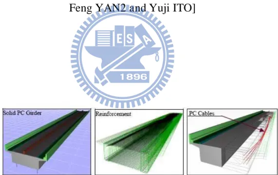
The 3 graphs in Figure 5 show a PC superstructures and its arrangement of reinforcement and PC Cable. By item selecting or object operating, the concrete and steel are separated shown clearly. The three graphs in Figure 6 show the responses of rigid frame bridge under Level 2 transverse earthquake. The step solid deformation response with original wire frame model is displayed on the left. Pier parts are modelized as fiber elements and its section defined strain damage accompanying with the whole frame displacements is shown in the middle. Frame element internal forces (red line: moments, green line: shear forces) and supported nodal reaction at each step is displayed on the right. (Fig 3.12)
5) Predicted Disaster Demonstrations [12]
Natural disasters, such as flooding, firing, typhoon, earthquake (especially in Taiwan), can be heard of nearly every day from TV or newspaper. Disaster
28
prediction and reduction are very important around the world nowadays, especially for populated city. The success of disaster prediction and loss reduction depends not only on the researchers‟ precise forecast to the possible damage, but also on the government and citizen consciousness on the potential dangers. Therefore how to present the future disaster to the related persons becomes an essential part on the success of disastrous reduction activity. (Figure 3.13)
3.4.1 The importance of Compressive Strength Test
Structural materials get through lots of revolution through centuries, from woods to bricks until concrete, which is undoubtedly playing an important role in construction material and one of the most common properties of concrete is compression. In addition to that, the amount of concrete consumed stays high in the construction industry. In consequence, compressive-strength test becomes the most common and basic experiments in material laboratory. Because of vital importance, it is strongly recommended to students to build up a reinforced memory on the understanding and importance of compressive-strength test. In civil engineering, the consumption of concrete is huge amount every day. In order to provide safety standard for construction, compressive-strength test is of vital importance (Fig 3.14). The result of the test from cast cylinders may be used for quality control, acceptance of concrete, or for estimating the concrete strength in a structure for the purpose of scheduling construction operations such as form removal or for evaluating the adequacy of curing and protection afforded to the structure.
29
Concrete mixtures can be designed to provide a wide range of mechanical and durability properties to meet the design requirements of a structure. The compressive strength of concrete is the most common performance measure used by the engineer in designing buildings and other structures. The compressive strength is measured by breaking cylindrical concrete specimens in a compression testing machine.
Due to the importance of concrete, compressive-strength experiment is chosen as the main experiment in the virtual laboratory. Through the presentation, students can easily understand the behavior and features of concrete.
In traditional education system, students can only focus on lectures or study materials but no self-experience. They can only imagine the behaviors between particles by words or arithmetic. However, if a series of material experiments will be demonstrated through simulation as a novel teaching system in education, students can feel like immersing themselves in the situation and can fully understand every process in the experiments before carrying out by his/her own. In this way, students can no longer just imagine how things go; instead, they can take reference on the animation before any experience will be carried out.
In this research, 3ds Max is implemented for building up the laboratory components and tools, and Virtools, as the development platform for producing virtual reality and virtual interaction.
30
Chapter 4 Construction of Virtual Civil Engineering Material
Laboratory
As discussed in the previous chapters, to utilize the technique of Virtual Reality (VR) in education is an essential aspect in this computer era. In this chapter, a prototype of Virtual Laboratory related to Civil Engineering material experiments is constructed. And a demonstration of the system is also provided.
4.1 Design of the Virtual Laboratory
The first step to the research is to figure out the procedures and detailed preparations for the completion of the project. As a result, data collection is a vital step before any work is carried out.
The Civil Engineering Material Laboratory of the department of civil engineering, National Chiao-Tung University will be totally converted to a Virtual Material Laboratory in this paper which provides opportunity for students to possess better understanding on the construction materials through 3D interaction effect.
In order to enhance the authenticity and more precisely modeled, equipments and tools related to the experiments was pictured including the interior components.
31
Since only the Compressive Strength Test is focused, the procedure for this experiment is fully analyzed, i.e.: to run the experiment once to find out if any difficulty involved in it before the design of the animation.
4.2 Construction of Scenes and equipments
Classroom:
To set up the classroom, students can take advantage of some of the build in drawing functions. The most important components of building a classroom will be walls and windows. For the parts of the walls, choose the create menu, and select AEC Extend. There shows the object type: Foliage, Railing and Wall. Choose the icon, wall, and create the surrounding model (Fig 4.1). Remember to press the „enter‟ key to save every input dimension in the Parameters Section; otherwise, the created figure will be gone.
When the walls are completed, then follows by the selection of Windows and Doors in the create menu to build up windows and doors for the laboratory. The Window selection shows the types of: Awning, Casement, Fixed, Pivoted, Projected and Sliding. The most suitable one will be the Pivoted style. Attaching the windows requires the step of excavation on the wall (Fig 4.2). For the part of door, the selection shows: Pivot, Sliding and Bi-fold; and the chosen one is Sliding. (Fig 4.3)
32
After accomplishing the space model, press on the hot key “m” in the keyboard for Material Editor (Fig 4.4) to create appropriate material for the wall, ceiling, windows and doors. In the material editor, we can open the “Material Browser” and choose “View List” for the appropriate material. If there is no suitable one, we can search through the internet and create a new attachment file in the list starting with “new” in the “Browse From” and then select “Bitmap”. Here the file selection format appears and then input the desired image for a newly built material. (Fig 4.5)
Lighting:
When creating a 3D environment, aside from the attachment of material, one of the most important aspects is lighting. All is just because of the realistic effect. Go to the create panel and choose the Lights option (Fig 4.6). Click the Free Spot button and place the light pointing directly down, perpendicular to the fixture. It is the easiest to use the top view to place the light because 3ds Max will automatically orient the light so that it is pointing away from the viewer no matter which view the user is in.
Conical concrete mold:
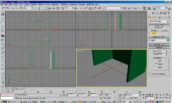
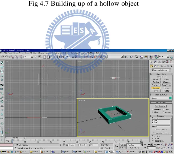
The conical concrete mold is used to make concrete models. This model is actually a hollow cylinder which will then be separated in two halves during the taking out of the concrete column during the animation. The process mainly focus on the functions of Mirror and Boolean. A hollow object is made by using the Boolean function in the Compound Object selection. Create two overlapping objects, but the height of the second one should be a bit taller than the other (Fig 4.8), overlap the two together with both ends remaining outside, and choose
33
Boolean in the selection of Compound Object. Select the shorter one and press on the “Pick Operand B” and follow by a click on the taller one. The hollow model is then completed (Fig 4.9). The mold contains a little rust, so the image containing rust is highly recommended in order to enhance the sense of reality. (Fig 4.10)
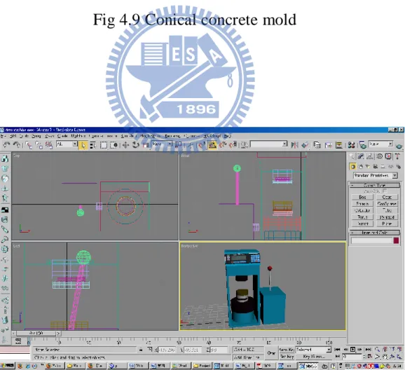
Compressive strength equipment:
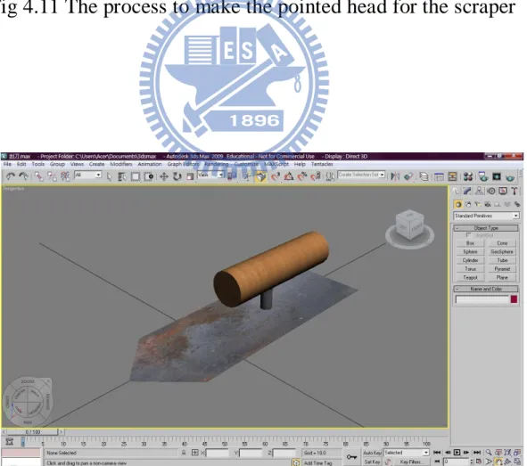
At the first sight on the picture, it seemed that this equipment require lots of technique in drawing; however, it only required more steps, but not technique when compared to others. It is mainly formed by boxes, cylinders and spheres. (Fig 4.11) For the main body of the machine which contains a hollow part, the process is the same as that of the conical concrete mold which requires the Boolean function. In order to enhance the reality of the machine, the buttons on top of the machine will be created in Photoshop. It is saved as an image, and later on will be imported as a material like the previous step described in the part of the classroom.
Scraper:
The building up of scraper requires the formation of a rectangle and two cylinders. The only complicated process is the shaping of the pointed head of the metal. First, the Width Segment in the Parameters Section is filled 3. It is like cutting the component into 3 parts and do further shaping. Get to the Modifier List and select Edit Mesh. Expand the list on Edit Mesh and choose Vertex. The points of the segments on the model will be colored with blue dots (Fig 4.12). Select the 2 points in the middle for making the descending pointing shape. The
34
selected points will be colored in red. Here, just a pull to the desired length, the pointed shape is completed (Fig 4.13).
Tray:
The model is formed by a two rectangles by using the function of Boolean. The Boolean process is the same as that of conical compressive mold. (Fig. 4.14)
Stick:
The stick is the formation of conical by adjusting the diameter to a very low value compared to the height. (Fig 4.15)
4.3 Integration of the classroom with the experiment components:
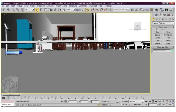
All the objects including the classroom as well as the experiment components are uniquely built and each of them are saved as a 3ds Max file separately. As a result, they have to be integrated together with the classroom model to create a complete laboratory model.
The integration requires the function Plane to build up a floor so that each model can be appeared on the same level. Without the ground, the models will appear in height difference and look like hanging in the space (Fig 4.16). Since the floor is uniquely built, ratio difference has to be adjusted by “Select and Uniform Scale” to make the edges attached to the wall bottom of the classroom
35
coincidentally. After the completion, import all the elements and put into position.
For the repeated model, make use of the Clone Option by first selecting the model and press the Shift key, move the object and release the mouse. After the step, the Clone object window appears. Select Instance in case of any change on the model, the cloned objects will be changed simultaneously as well and enter the number for the copied objects (Fig 4.17). The accomplished file then has to been output as .NMO, .CMO, VMO formats. Fig 4.18 shows the integration of the laboratory.
4.4 Production of the Virtual Material Laboratory
This section illustrates the production procedures of 3D interaction through the utilization of Virtools 3D/VR. The procedures are as follow:
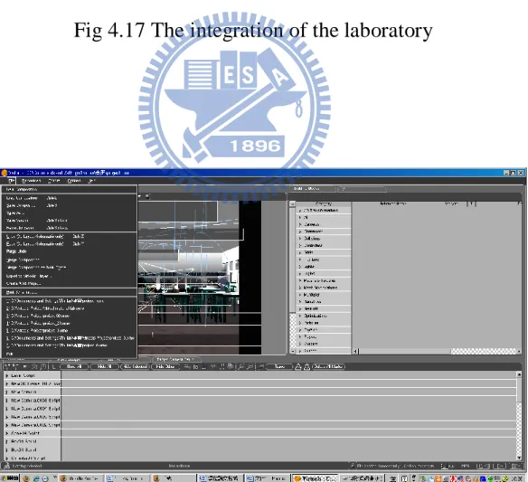
1. Model Import
The first step is to open the software, Virtools, and select the appropriate file name in “Import File” in the “File” bar (Fig 4.19). After the import of the model, the whole laboratory is appeared in total darkness (Fig 4.20), light should be added to bring ignition.
36
The coming task will be the placement and set up of the camera and light. First of all, set up a camera from the 3D Layout window which can be found on the tool menu on the left hand side, and adjust to the appropriate viewpoint, distance and angle. Press on the IC button on the left hand side to save the set up. During the process, if any unsatisfactory is found, make use of the Restore IC button to return to the previous condition.
The next task is to bring a light to the laboratory. To do this, just a click on the light source found in 3D Object set up area to bring ignition. However, the distance coverage of Point Light cannot be set to infinity; all to be done is to set the lighting mode to Direction Light. In this way, the light coverage is unlimited. If only one light is set up, the laboratory will be too dim; as a result, more light sources should be added in different positions with different directions for shadows casting to create a more realistic phenomenon. The result is shown in Fig 4.23.
2. Set up of the control of the camera:
Create a new Camera and then a new Script window. Follow by the adding of Building Block. In the selection of it, choose 3D Transformations, then Constraint and finally Look At. Click on the Building Block and adjust the speed to 10% to let the camera automatically capture the location of the 3D frame. The higher the percentage, the faster the camera goes. Then select Cameras/ Movement/ Keyboard Camera Orbit. Set the keys “Pg up, Pg down,” in the keyboard which represent “zoom in, zoom out, up, down, left and right” function in the animation process respectively.
37
Select Level Script in Level manager for a new script and add Building Block as follow:
1. In the selection of Building Block, choose Controllers/ Mouse/ Mouse Waiter. This set up shows that during the right clicking on the mouse on the target object, the 2D text appears and one more click to hide the text (Fig 4.24)
2. For the detection of the clicking on targets, choose Interface/ Screen/ 2D Picking in the same entity. (Fig 4.25)
3. The final step is to handle the 2D text frame color. In the Building Blocks, get to the Materal-Texture/ Basic/ Set Diffuse (Fig 4.26). The function „Set Diffuse‟ provides various color selection. Users can choose their favorite color for the text shown in the work.
4. Button set up for the start of the animation (Compressive Strength Test)
The set up of this button is to let users get abundant time to walk around the laboratory before getting to the experiment. In the Building Block, select Logics/message/wait message and then select On Click (Fig 4.27).
5. 2D messaging in the animation
In the experiment, certain text descriptions should be shown to students in order to follow the experiment procedures easily. Get to the Building Blocks and follow by Interface/ Text/ Text Display. Click on the Text Display box for messaging and color can be changed as well in the function „Set Diffuse‟ (Fig 4.28).
38 6. Work Display
Aside from displaying the work in Virtools, it can also be demonstration through network. The accomplishment is output as htm format so it can be browsed in webpage mode (Fig 4.29). In addition to that, the output can also support Firefox, Mozilla and Netscape etc. Before opening the file, the network will automatically download and install 3D Life Player.
4.5 Demonstration of Virtual Material Laboratory:
When the whole set up of the laboratory is completed, let‟s get inside to have a look at it (Fig 4.30). Firstly, let‟s take a look at the right side of the laboratory. It mainly places the tools for experiments: trays, funnels, flasks, sieves, scrapers, water basin (Fig 4.31). On both ends, are the concrete mixing machine, ovens and balance (Fig 4.32). For the middle part of the laboratory, it is equipped with tables and chairs for students to do some writing work (Fig 4.33). Conical concrete molds are placed at the end of it. Lastly, the left hand side of the laboratory mainly shows the machines for experiments: gravels holder, sieve machines and compressive strength machine (Fig 4.34& 4.35)
In this virtual material laboratory, it involves some parts of animation interactions:
39 1. Control of the Camera:
The set up involved the keyboard control of the camera as the first person to view the whole environment. The inner set up of the keyboards is as follow: Pg up=move forward (Fig 4.36)
Pg down=move backward (Fig 4.37) =look up (Fig 4.38)
=look down (Fig 4.39) =turn left (Fig 4.40) =turn right (Fig 4.41)
With this set up, users can walk around the virtual laboratory and view all the tools and machines easily in any way they prefer. Quoting from the introduction in Chapter 2, memories can be reinforced in mind more easily when users are getting themselves in an immersive environment. With the Pg up button, when users desire to have a much closer look at any element they want, they only press on the button to get a close up view.
2. Experiments selection:
Before getting to the inside of the laboratory, the top right hand side of the laboratory shows the control bar of the experiment selections with the name of the department (Fig 4.42). With a single press on the button, a list of material experiments is expanded (Fig 4.43). Altogether, there are 11 material experiments for students to practice. Users can select any of the experiments and just make a single click on any one of them; the window will bring them to the corresponding machine. There users can press on the target machine to see the animation effects or procedures.
40 3. Text descriptions of tools and machines:
When users first get into the laboratory, they may have no idea on the tools and machines. This may let students lack for interest in participating any further practice. As a result, this function is designed for users to get a better understanding on the tools and machines when they are walking around the laboratory, and it is designed by just clicking on the mouse. When users click on the mouse of the target object, the name of the machine/tool appears (Fig 4.44). However, the names of the selected object cannot be appeared together. When users click on another target, the name of the previous one will disappear and show up the name of the new one.
4. The start of the Compressive Strength Test:
The animation experiment of the project is the Compressive Strength Test. Students can either get to the compressive strength machine by walking to it or by clicking on the name of the experiment on the list. When users get to the front of the compressive machine, they just have to make a click on the red ball of the handle to start the animation (Fig 4.45). During the whole procedure, statements describing the steps of the experiment process are shown accordingly (Fig 4.46 & 4.47).
4.6 Evaluation of the Virtual Material Laboratory:
Through the whole production process, the 3D interaction is finally converted by Virtools 3D/ VR in this project. Make use of the interaction properties in the 3D
41
multi-media equipments and animation to create a more realistic vision to let the users experience a total immersive environment.
With the fast growing pace in VR application to education, more and more virtual experiments will be added to this virtual laboratory. By that time, students are believed to become more and more interested in learning and the education efficiency result will highly be enhanced.
Lastly, there are some points needed to be paid attention to during the procedures:
1. Image attachment:
For material edition, the size of the image selected is too large and caused sudden shut down for the computer after imported to Virtools. As a result, it is highly recommended that the size of the imported image should be based on N square pixels to avoid capacity occupying.
2. Interaction should be designed in Virtools instead of 3ds Max to avoid rises in data capacity and result in heavy burden for the computer. It is recommended that actions should be presented by Script in Virtools.
3. Virtools does not permit any total turn around action. If any animation occurs with this limit, it should be controlled not to get beyond the limitation.
4. The undo function in Virtools cannot be used consecutively. It means that it can be used once only. If any changes are made, always remember to press on
42
the “IC” button to set the initial condition. If it has to be restored to the previous situation, press on “Restore Initial Condition”.
5. For displacement, rotation and zooming in/out actions, it is recommended to design in Virtools in order to lower the capacity consumption.
![Fig 3.3 Data glove [images-amazon.com]](https://thumb-ap.123doks.com/thumbv2/9libinfo/8712222.200064/60.893.269.755.116.1015/fig-data-glove-images-amazon-com.webp)