Modeling of nonlinear pulse propagation
in periodic and quasi-periodic
binary long-period fiber gratings
Gia-Wei Chern, Jui-Fen Chang, and Lon A. WangInstitute of Electro-Optical Engineering, and Department of Electrical Engineering, National Taiwan University, Taipei, Taiwan
Received July 18, 2001; revised manuscript received January 10, 2002
A generalized transfer-matrix method is used to model nonlinear pulse propagation in a binary long-period fiber grating (LPFG). Two interface matrices are used to describe power coupling at the heterointerfaces, as in the linear case. Nonlinear phase shifts and pulse dispersion through the two basic regions are modeled by coupled nonlinear Schro¨dinger equations. Based on the generalized transfer-matrix model, a local intensity-dependent detuning parameter is introduced with which we investigate the general conditions for complete switching. Nonlinear switching in a quasi-periodic Fibonacci LPFG is also studied, and it is shown that com-plete switching can be achieved in such a quasi-periodic grating. © 2002 Optical Society of America
OCIS codes: 050.2770, 060.4370, 060.1810.
1. INTRODUCTION
Optical fibers are ideal for use in nonlinear interactions because they provide strong beam confinement over long propagation distances. Inasmuch as most optical fiber materials are subject to inversion symmetry, the nonlin-ear operation of devices made from such materials often utilizes the much weaker third-order Kerr-type nonlinearity.1 A number of interesting phenomena have been observed and explored in both counterpropagating and copropagating waveguide configurations. Optical bistability2,3and Bragg grating solitons4,5are observed in nonlinear distributed-feedback structures. All-optical switching is shown in codirectional coupling devices such as nonlinear coherent directional couplers,6–8 grating couplers,9and rocking filters.10 Switching behaviors are also observed in other fiber-based devices including those with a Mach–Zehnder configuration11,12 and nonlinear-optical loop mirrors.13,14 The switching behaviors exhibit periodic variation with respect to input power because of their special interferometric configurations.
A long-period fiber grating (LPFG) was originally pro-posed for use as an all-fiber band-rejection filter.15 The LPFG can couple light from the core mode to the copropa-gating cladding modes when the phase-matching condi-tion is satisfied. Recently, optical switching, pulse re-shaping, and optical limiting phenomena were observed in photoinduced LPFG’s at pulse intensities in a range of several gigawatts per square centimeter.16
The nonlinear propagation of pulses with durations of a few tens of picoseconds has also been analyzed in detail by use of nonlinear coupled-mode equations.17 Two types of typical intensity-dependent transmission were ob-served. For the first type, the central frequency of the pulse is adjusted to satisfy the linear phase-matching point. The energy transfer from core mode to cladding mode is almost complete when the input intensity is
small. However, at high input intensity, the central in-tense portion of the pulse becomes detuned off resonance as a result of the Kerr effect and thus remains in core mode. Only the low-intensity wings of the pulse are coupled to the cladding mode. In this case the remainder of the high-intensity pulse in the core mode is narrowed. The second type, in which the central frequency of the pulse is near the transmission node of a linear LPFG, is the off-resonance case and is our main concern here. At low intensities the pulse remains almost entirely in the core mode. As the intensity is increased, the central high-power part of the pulse becomes detuned toward the phase-matching point and starts to couple to the cladding mode. The transmission curve exhibits a limiting char-acteristic at high input intensities. Such operation of the LPFG can thus serve as an optical limiting device. Based on these two basic operations, other schemes have also been proposed. For example, through cross-phase modulation a pump pulse can switch a weak signal pulse.18 It was also shown that the intensity required for all-optical switching can be reduced to the order of 100 MW/cm2by the introduction of uniform phase-shifting re-gions within two LPFGs.19
In this paper first we extend our previously proposed transfer-matrix approach for the linear transmission properties of a photoinduced binary LPFG20to model non-linear pulse propagation. The nonlinear transmission curve of an ideal binary LPFG is compared with that of a pure sinusoidal LPFG with the same grating strength. Based on this formalism and for a quasi-continuous-wave approximation, we introduce a local normalized detuning parameter. This detuning parameter is intensity depen-dent and plays a crucial role in the switching behavior of a LPFG. The effects of self-phase modulation and of cross-phase modulation on the nonlinear coupling of pulses in a LPFG can be analytically studied by use of
such a parameter. We consider mainly the off-resonance operation of a LPFG. Because nonlinear coupling is con-trolled by the instantaneous intensity, high- and low-intensity parts of the pulse will be directed into different output modes, and this will result in pulse breakup and degrade switching performance. The use of square pulses to prevent pulse breakup in nonlinear switching was proposed.21 It is also found that the switching ratio in an LPFG can be greatly enhanced for a square pulse. To prevent the unnecessary complexities that would be in-troduced by the influence of pulse shape, we use a square pulse in the studies. For a given input intensity of the square pulse, we demonstrate that nonlinear transmis-sion in a uniform LPFG can be equivalent to linear trans-mission in a chirped LPFG. This equivalence is based on the intensity-dependent local normalized detuning pa-rameter and is a useful aid to understanding the switch-ing behavior. General conditions of the detuning distri-bution for complete switching are also discussed. We apply the generalized transfer-matrix model to study the nonlinear transmissions of pulses over a quasi-periodic Fibonacci LPFG; almost complete switching is demon-strated when a square pulse is used as the input. Be-cause a quasi-periodic grating lacks short-ranged order and the long-range order may be obscured by the intro-duction of nonlinearity, the method of determining the ex-istence of complete switching is rather interesting. The evolution of power and local detuning is investigated and compared with that of a periodic LPFG. After local aver-aging, complete switching can be explained by the equiva-lency of a chirped linear grating.
The paper is organized as follows: In Section 2 a gen-eralized transfer-matrix model for nonlinear pulse propa-gation in an ideal binary LPFG is developed. Also, pa-rameters such as critical power and effective areas are introduced. In Section 3 we consider a quasi-cw pulse and introduce a local intensity-dependent detuning pa-rameter that characterizes the in-phase superposition of couplings through the interfaces of adjacent periods. The nonlinear transmission of square pulses is also stud-ied. Section 4 is devoted to analysis of nonlinear switch-ing in a periodic LPFG. Through the analysis of the local detuning parameter, the transmission characteristics of a given intensity can be equivalent to those of a chirped LPFG in the linear coupling regime. We also discuss the general conditions of the slowly varying detuning param-eter for the ideal complete switching. The nonlinear cou-pling characteristics of a quasi-periodic LPFG are dis-cussed in Section 5. By using the nonlinear transfer-matrix model we demonstrate almost complete switching in a quasi-periodic LPFG which can be concisely ex-plained by investigation of the local detuning parameters.
2. MODELING OF NONLINEAR PULSE
PROPAGATION IN BINARY LONG-PERIOD
FIBER GRATINGS
A model of the linear transmission properties of a binary LPFG was recently developed by Chern and Wang20and was based on the transfer-matrix method and mode per-turbations. An ideal binary LPFG is composed of two ba-sic regions, which we designate region 1 and region 0 in
what follows. Region 0 is the usual fiber structure, whereas region 1 is exposed to UV irradiation and the core refractive index is thus increased by an amount ⌬nUV. In the phase-matching condition, power cou-plings between core mode and cladding modes can occur in such a grating.20,22 We use conventions introduced in Ref. 20 for quantities that belong to these two basic re-gions. Quantities written with overbars belong to region 0; the unbarred quantities are of region 1. For example, mode fields of the two regions are denoted (e¯j,h¯j) and (ej,hj), respectively, where the subscript j indicates the mode order, e.g., LP01for the fundamental core mode and LP02for the first cladding mode.23 In our previous mod-eling of a binary LPFG we treated the mode fields of re-gion 1 as perturbations of the unperturbed mode fields of region 0 and related the perturbation expansion coeffi-cients to the conventional coupling constants. Here we shall assume that these mode fields satisfy the following orthogonal relations and are normalized to carry unity power:
1 2
冕
A⬁共ej⫻ hk兲• zˆdA ⫽ ␦jk, (1) where ␦jk is the Kronecker delta function. Similar ex-pressions hold for the mode fields in region 0. As dis-cussed in Ref. 22, in an LPFG we may consider only forward-propagating modes because the excited backward modes are small. The electric fields of an optical pulse in the two regions can be written as
E共r, t兲 ⫽
兺
j
Aj共z, t兲exp关i共jz⫺0t兲兴ej, (2a)
E¯ 共r, t兲 ⫽
兺
j
A
¯j共z, t兲exp关i共¯jz⫺0t兲兴e¯j, (2b)
where Aj(z, t) and A¯j(z, t) are the slowly varying enve-lopes of the pulse in mode j that belong to regions 1 and 0, respectively. j and ¯j are the corresponding propaga-tion constants, and 0 is the central frequency of pulse. When such a pulse crosses the heterointerface between the two regions, because of discontinuities in the guiding structures, mode couplings occur at such interfaces. We can derive the transmission coefficients by requiring con-tinuity in the tangential electric and magnetic fields. Be-cause this process is linear, the coupling between the mode amplitudes can be described by a matrix. For ex-ample, assume that a cw wave field with frequency is incident upon the heterointerface from region 0 to region 1; we may use the following matrix equation to describe the changes in mode amplitude:
A共兲 ⫽ F共1兩0兲共兲A¯ 共兲. (3) Here we have used column vectors A() ⫽ 关A01co(),
A02cl(), A03cl(), ...兴Tto represent mode amplitudes of the cw wave field in region 1. Here, superscripts co and cl are used to denote core and cladding modes. The mode amplitudes in region 0 are treated similarly. And the in-terface matrix has the following form (the details of deri-vation can be found in Ref. 20):
F共1兩0兲共兲 ⫽
冋
1 ⫺ D01co 01– 0co–cl 01 co ⫺ 0 cl 0 – 01cl–co 0cl ⫺01 co 1 ⫺ D0cl 2册
, (4)where D01co and D0cl are defined in Appendix A of Ref. 20 and they are included to satisfy power conservation to the second order in perturbation. 01– 0co–cl is the conventional coupling constant in coupled-mode theory and is defined as22 01– 0co–cl 共兲 ⫽ 0nco 2 ⌬nUV
冕
Aco et01co*共兲et 0cl 共兲dA. (5)Note that the coupling constant is a function of fre-quency. In addition, all the coefficients D ⫽ D() and  ⫽ () in Eq. (4) are functions of frequency. Thus in the time domain we may use the following response ma-trix to describe the coupling of the pulse in the two modes:
A共t兲exp共⫺i0t兲 ⫽
冕
⫺⬁t
F共1兩0兲共t ⫺ t⬘兲A¯ 共t⬘兲exp共⫺i0t⬘兲dt⬘, (6)
where A(t) ⫽ 关A01co(t), A02cl(t), A03cl(t), ...兴Tand F(1兩0)(t) is the Fourier transform of F(1兩0)(). However, if the dura-tion of the pulse is tens of picoseconds, as in the descrip-tions that follow, the spectra of the amplitudes
A()exp(⫺i0t) will be quite narrowly centered at 0. In such quasi-cw pulses we may use the following ap-proximation for Eq. (6):
A共t兲 ⬵ F共1兩0兲共0兲A¯ 共t兲. (7)
Similar expressions can be used for pulses that cross the interfaces from region 1 to region 0, and the correspond-ing interface matrix is
F共0兩1兲共兲 ⫽
冋
1 ⫺ D01co 2 ⫺01– 0co–cl 01 co ⫺ 0 cl ⫺0 – 01cl–co 0cl ⫺01 co 1 ⫺ D0cl 2册
. (8)As for the propagation through the two regions, the evolution of mode amplitudes may be described by the fol-lowing coupled equations (here we take region 1 for example)17,19,24 A01co z ⫹ i 201⬙ co 2A 01 co 2 ⫽ i
冉
␥01– 01co–co兩A01co兩2⫹ 2兺
␥01– 0 co–cl 兩A 0 cl 兩2冊
A 01 co, (9)冉
z ⫹ ⌬Vg, 冊
A0 cl ⫹ i 20⬙ cl 2A 0 cl 2⫽ i
冉
␥0 – 0cl–cl 兩A0cl兩2⫹ 2␥0 – 01cl–co 兩A01co兩2 ⫹ 2兺
⫽ ␥0 – 0 cl–cl 兩A 0 cl 兩2冊
A 0 cl , (10) where j⬙⬅ d2j/d2 is the second derivative of the propagation constant with respect to frequency for mode
j. ⬅ t ⫺ (d01co/d)z is the retarded time for the core mode. ⌬Vg, is the group-velocity difference between core and cladding modes LP0cl . And the nonlinear phase-modulation coefficients are defined as
␥jk⫽ n20 c
冕
A⬁ 兩ej兩2兩ek兩2dA冕
A⬁ 兩ej兩2dA冕
A⬁ 兩ek兩2dA , (11)where n2 is the nonlinear Kerr index. Note that to be consistent with first-order perturbation treatment of in-terface coupling coefficients there is no need to distin-guish␥jkbetween the two regions. The effective area of mode j is related to the nonlinear phase-modulation coef-ficient as
Aeff, j⫽
n20
c␥jj
. (12)
Equations (9) and (10) describe the propagation of the pulses within regions 0 and 1 by taking into account the effects of dispersion, self-phase modulation, and cross-phase modulation. Combined with interface matrices (4) and (8), these constitute the governing equations to de-scribe the propagation of a nonlinear pulse in a binary LPFG. In Fig. 1 we compare the transmission curves for a binary and a uniform sinusoidal LPFG with equal length and linear coupling strength. [Physically, the in-dex modulations are chosen as ⌬nUV (binary) ⫽ /4⌬nUV (sinusoidal).] The modeling of a sinusoidal LPFG is based on the combined equations of coupled-mode theory and the nonlinear phase-modulation terms on the right-hand sides of Eqs. (9) and (10) (cf. Refs. 17 and 19). The guiding structure has a step-index profile, and the calculated modal properties can be found in detail in Ref. 22. The fiber parameters are as follows: aco ⫽ 2.625m, acl⫽ 70m, nco⫽ 1.456, and ncl⫽ 1.45. The resonant cladding mode is chosen to be the LP04 mode. The linear coupling constant01– 0co–cl ⌳ used in cal-culation is normalized as/2N, where N is the number of cells in a binary LPFG, so complete linear switching can be achieved at the resonant wavelength. The nonlinear phase-modulation coefficients are ␥co–co⫽ n20/cAeff,co, with Aeff,co⫽ 48.2m2, ␥co-cl⫽ 8.67 ⫻ 10⫺3n20/c, and
␥cl–cl⫽ 6.574 ⫻ 10⫺3n20/c. The central wavelength of the pulse is0⫽ 1.55m and corresponds to off-resonant operation. The initial pulse is a transform-limited Gaussian pulse with half-width 60 ps. Besides, we nor-malize the input power by the critical power Pc that was introduced by Jensen for nonlinear coherent directional couplers of cw couplings6and is redefined in our case as
Pc⫽
401– 0co–cl ␥01– 01co–co ⫺ 2␥01– 0co–cl
. (13)
For Fig. 1(a) the number of cells is 120 (Lg ⫽ 69.5 mm). At this length the transmission curves of the two gratings are barely distinguishable in the linear limit and in higher-intensity regions where the pulse is detuned from the resonance. Little deviation is found at the power ⬃1 Pc at which nonlinear phase modulations bring the pulse into resonance. This deviation can be at-tributed to the difference in interplay between linear cou-plings and nonlinear phase modulations of the two grat-ings. For a sinusoidal LPFG, both processes are distributed along the grating, whereas, for a binary
LPFG, couplings take place only at heterointerfaces be-tween regions 0 and 1. However, when many fewer num-ber of cells are compared, as for the case shown in Fig. 1(b), where N⫽ 15 (Lg⫽ 8.7 mm), a larger deviation at the critical power is observed, while two gratings remain similar in the linear limit and higher-intensity regions. This result implies that, as the number of periods de-creases, the nonlinear coupling behaviors that are due to these two different mechanisms near the critical power are more distinct. However, at the intensity region where the pulse is detuned, these two gratings are almost the same.
3. QUASI-CONTINUOUS-WAVE
APPROXIMATION AND
INTENSITY-DEPENDENT DETUNING PARAMETERS
In this section we consider the quasi-cw approximation, which is mathematically equivalent to neglecting the dis-persion terms in Eqs. (9) and (10). When the group-velocity difference is assumed small,17 the solution to these two equations is that the mode amplitudes acquire an additional nonlinear phase shift as
A01co共z, 兲 ⫽ A01co共0,兲exp兵i01co关A共0,兲兴z其,
A0cl共z, 兲 ⫽ A0cl共0,兲exp兵i0cl关A共0,兲兴z其, (14) and the phase shifts per unit length are
01co ⫽
冋
␥01– 01co–co兩A01co共0,兲兩2⫹ 2兺
␥01– 0co–cl 兩A 0
cl 共0,兲兩2
册
,0cl ⫽
冋
␥0 – 0cl–cl 兩A0cl共0,兲兩2⫹ 2␥0 – 01cl–co 兩A01co共0,兲兩2 ⫹ 2兺
⫽ ␥0 – 0 cl–cl 兩A
0
cl共0,兲兩2
册
. (15)Based on this result, the propagation of the quasi-cw pulse through region r can be described with the following matrix equation:
A关⌳共r兲,兴 ⫽ P共r兲关A共0,兲兴A共0, 兲. (16) Here z⫽ 0 is assumed to be the beginning of region r. When the phase shifts that are due to propagation con-stants are taken into account, the intensity-dependent phase-shift matrix is given by
P共1兲 ⫽
冋
exp兵i关01 co⫹ 01 co共A兲兴⌳共1兲其 0 0 exp兵i关0cl ⫹0cl共A兲兴⌳共1兲其册
, (17a) and similarly for region 0:P共0兲 ⫽
冋
exp兵i关¯01 co⫹¯ 01 co共A¯ 兲兴⌳共0兲其 0 0 exp兵i关¯0cl ⫹¯0cl共A¯ 兲兴⌳共0兲其册
, (17b) where⌳(1)and⌳(0)are the lengths of regions 1 and 0, re-spectively. Let us denote by An() the mode amplitudes at the beginning of region 1 in the nth period of the grat-Fig. 1. Core energy transmitted through a binary and a uniformsinusoidal LPFG as a function of normalized input peak power. The number of unit cells is (a) 120 and (b) 15 in each grating. Ec
is defined as the total energy of the pulse with input peak power
ing. Then, by using interface transfer matrices (4) and (8), we can express the transmission of the quasi-cw pulse through a unit period by the following matrix equation:
An⫹1共兲 ⫽ F共1兩0兲共0兲P共0兲共A¯n兲F共0兩1兲共0兲P共1兲共An兲An共兲. (18) We now consider resonance between the core mode and a specific cladding mode LP0. The phase differences be-tween rays coupled from core to cladding modes in the front and rear interfaces of regions 1 and 0 are just the differences in the arguments of the exponentials in Eq. (17): ⌬共1兲⬅ 共 01 co ⫺ 0 cl兲⌳共1兲⫹ 关 01 co共A兲 ⫺ 0 cl共A兲兴⌳共1兲, (19a) ⌬共0兲⬅ 共¯ 01 co ⫺¯ 0 cl兲⌳共0兲⫹ 关¯ 01 co共A¯ 兲 ⫺¯ 0 cl共A¯ 兲兴⌳共0兲. (19b) From Eqs. (4) and (8), because the cross-coupling coeffi-cients from region 0 to region 1 and from region 1 to re-gion 0 differ by a factor of ⫺1, in-phase coupling of the pulse through these two interfaces occurs when⌬(1)⫽ and⌬(0)⫽. We define the intensity-dependent phase-mismatch parameter of the nth period to be
n共1兲共An兲 ⫽ ⌬n共1兲⫺, (20a) n共0兲共A¯n兲 ⫽ ⌬n共0兲⫺. (20b) Assume that the duty ratio of each period is 0.5 and that in most cases the nonlinear phase-modulation coefficients satisfy␥co–coⰇ ␥co–cl,␥cl–cl; then the normalized detuning parameter within the nth period can be approximated as n共An兲 ⬵␥01– 01co–co⌳n兩A01,nco 兩2⫹␦n⌳n, (21) where␦nis the conventional definition of a linear detun-ing parameter with period⌳n:
␦n⫽ 共01 co⫺  0 cl兲 ⫺ 2 ⌳n . (22)
From Eq. (22) we can see that efficient couplings, say, in-phase couplings, of the pulse occur at time components such that ⬵ 0, and it is clear how the nonlinear phase modulations modify the resonance conditions.
For a nonlinear pulse propagating in a uniform LPFG, because of the intensity-dependent nonlinear phase modulation the coupling behavior is different for low- and high-intensity parts of the pulse. This difference results in eventual pulse breakup and incomplete switching. Because nonlinear complete switching can be realized through a dual-core fiber coupler by use of a square pulse,21here we investigate the transmission of a square pulse through a uniform LPFG. Figure 2 depicts the relative transmission curve for an almost ideal square pulse (FWHM, 75 ps), where the relative transmission is defined as the ratio of the integrated output power to the initial power and the input peak power is normalized to
Pc. The input pulse’s profile is shown schematically in the inset. The resonance cladding mode is chosen to be LP04, as used in the simulation of Fig. 1. The central wavelength of the pulse is set to 1.55 m, which corre-sponds to off-resonance operation. Grating strength ⌬nUV⫽ 2.51 ⫻ 10⫺4and the length of the LPFG are cho-sen to produce complete linear coupling at res ⫽ 1.541m. It can be seen that the best switching ratio
for the square pulse is more than 95% at the input peak power of⬃1.52 Pc. As was the case for Ref. 21, such an increased switching ratio for the square pulse is due to the breakup of the depressed pulse.
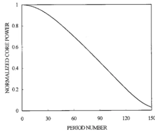
Figure 3 shows the evolution of normalized transmitted power along the LPFG with respect to the almost com-plete switching input peak power 1.52 Pc for the square pulse. In Section 4 we shall explore the complete cou-pling behavior by investigating the distribution of local detunings.
4. EQUIVALENCE OF NONLINEAR
GRATING WITH CHIRPED LINEAR
GRATING AND CONDITIONS FOR
COMPLETE SWITCHING
From Eqs. (19) it can be seen that the phase differences between rays coupled from two adjacent interfaces of re-gion 1 and 0 are intensity dependent. For a given inten-sity, the nonlinear phase modulation that contributes to the phase differences within a period can be regarded as an additional phase shift for linear coupling, i.e., the lengths of regions 1 and 0 are enlarged. Thus we can re-write Eqs. (19) as ⌬共1兲⫽ 共 01 co⫺  0 cl兲⌳ eff 共1兲共A兲, (23a) Fig. 2. Fraction of the output power emerging from the core plotted versus normalized input peak power for a 75-ps square pulse as input. Inset, normalized input pulse profile. This pulse profile is also used in Figs. 3, 4, and 6 below.
Fig. 3. Evolution of the normalized transmitted core power through a uniform LPFG with respect to input peak power Pin ⫽ 1.52 Pcof the square pulse.
⌬共0兲⫽ 共¯ 01 co⫺¯ 0 cl兲⌳ eff 共0兲共A¯ 兲. (23b) Here we have defined the effective periods,⌳eff(1)and⌳eff(0), of the two basic regions. These effective periods depend on the intensity of the wave fields inside the correspond-ing regions; the explicit dependence can be found from Eqs. (19) and (23) as ⌳eff共1兲共A兲 ⫽
冋
1 ⫹ 01 co共A兲 ⫺ 0 cl共A兲 01co⫺ 0cl册
⌳ 共1兲, (24a) ⌳eff共0兲共A¯ 兲 ⫽冋
1 ⫹ ¯01co共A¯ 兲 ⫺¯0cl共A¯ 兲 ¯01co⫺¯0cl册
⌳共0兲. (24b) As the optical power is coupled between the core and the cladding along a uniform LPFG, an equivalent LPFG composed of chirped effective periods for linear coupling results. However, it is worth noting that the model of an equivalent chirped LPFG, which is designated for a spe-cific intensity, favors square pulses rather than bell-shaped pulses to prevent the appearance of complexities introduced by the pulse shape. Such an equivalence is similar to the linear effective waveguide of spatial soli-tons proposed by Snyder et al.25 Thus by using a square pulse of a certain intensity one can obtain the linear transmission spectrum of the equivalent chirped LPFG. With such a corresponding linear spectrum, we can ex-plicitly show the intensity-dependent resonance shifts for nonlinear switching. To demonstrate this, we take the square pulse in Fig. 2 as an example. The central wave-length of the square pulse is 1.55 m, which is that for off-resonance operation, and the parameters of the LPFG are the same as those discussed in Section 3. Figure 4(a) shows the spectra of the equivalent chirped LPFGs with input peak powers Pin⫽ 10⫺4, 1.52, 2.25 Pc; and their corresponding effective periods derived from Eqs. (24) are shown in Fig. 4(b). It can be seen that when the input power is in the linear limit, as it is for Pin⫽ 10⫺4Pc, the spectrum of the equivalent chirped LPFG is almost the same as the spectrum for linear transmission. This is so because the nonlinear phase-shift terms in Eqs. (24) can be neglected at such low intensity and thus the effective periods are almost unchanged. The pulse energy trans-ferred from the core mode to the cladding mode is almost zero in this case. However, as the input peak power is increased, the spectrum of the equivalent chirped LPFG composed of effectively lengthened periods is shifted to longer wavelengths, and the transmission of the pulse starts to degrade from unity. Particularly at the powerPin⫽ 1.52 Pc, the dip in transmission loss of the equiva-lent spectrum is just shifted to the central wavelength of the pulse, which is clearly consistent with the best switch-ing contrast in Fig. 2. The decreasing effective periods along the LPFG shown in Fig. 4(b) manifest the process of continuing energy transfer from core mode to cladding mode. If the power is further increased, as can be seen for Pin⫽ 2.25 Pc, even longer effective periods once again detune the transmission of the square pulse and result in worse switching behavior. This situation corresponds to the rising part of the relative transmission curve in the higher intensity region illustrated in Fig. 2.
As we mentioned above, nonlinear coupling in a uni-form LPFG for a square pulse of a chosen intensity can be regarded as linear coupling in an equivalent chirped LPFG. Additionally, we demonstrated in Section 3 that complete switching can be achieved for a square pulse with a specific intensity through a uniform LPFG. In contrast to complete linear switching in a uniform LPFG for which in-phase coupling, say, ⫽ 0, is always satisfied,22 nonlinear coupling implies that complete switching still occurs even if in-phase coupling is not maintained throughout the grating, whether for linear or nonlinear coupling. From the definition of the local de-tuning parameter in relation (21), the lengths of period and nonlinear phase modulation are the two factors that influence the variation of the detuning parameter along the grating. In what follows, we investigate the distribu-tion of this parameter in several interesting cases, such as for complete linear switching in nonuniform binary LPFGs and for complete nonlinear switching in uniform LPFGs.
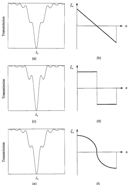
For simplicity, we first consider linear coupling in three typical nonuniform LPFGs whose spectra are depicted in Figs. 5(a), 5(c), and 5(e). These gratings correspond to a linear chirped grating, two uniform parts with different Fig. 4. (a) Transmission spectra of the equivalent chirped grat-ings for various input peak powers of the square pulse. The wavelength marked by the arrow is the center wavelength of the input pulse. (b) Effective periods of the equivalent chirped grat-ings for various input peak powers of the square pulse.
grating periods, and a quadratic chirped grating, respec-tively. In each grating the existence of complete linear coupling at a certain wavelength0can be demonstrated by use of the generalized transfer-matrix method pro-posed in Section 2. Then, to show clearly the linear cou-pling process for wavelength0in three gratings, we plot the respective evolutions of normalized detuning param-eter in Figs. 5(b), 5(d), and 5(f). Assume that the total period numbers of LPFGs are the same as N; for these cases we find that there is a common feature: The distri-bution of is halved and antisymmetrical with the grat-ing center. Thus we have the following relation for the two halves (assume that N ⫽ 2M in what follows):
M⫺m⫽ ⫺M⫹m⫹1, m⫽ 0, 1, 2,..., M ⫺ 1. (25)
Herenis the normalized local detuning parameter of the
nth period. Using this parameter, we can express the unit transfer matrix as follows20:
F共兲 ⬅ F共1兩0兲P共0兲F共0兩1兲P共1兲 ⫽
冋
⫺␦2exp共⫺i兲 ⫹␥2 ⫺␦␥关1 ⫹ exp共i兲兴
␦␥关1 ⫹ exp共⫺i兲兴 ⫺␦2exp共i兲 ⫹ ␥2
册
. (26) The same notation as in Ref. 20 is used here and is not to be confused with the normalized detuning and nonlinear coupling coefficients. ␦represents the self-coupling coef-ficient through the heterointerface, and we assume that this parameter is the same for core and cladding modes for ideal two-mode coupling.20 ␥ is the cross-coupling co-efficient of the core and cladding modes through the het-erointerface. Inasmuch as the grating strength is kept constant, the unit transfer matrix of the nth period is ex-clusively a function of the corresponding local normalized detuning parameter; thus we have Fn⫽ F(n), where the dependence F() is given in Eq. (26). The total transfer matrices of the front and rear halves areFig. 5. (a), (c), (e) Transmission spectra of the three typical nonuniform LPFGs. Note that in each grating complete linear coupling occurs at wavelength0. (b), (d), (f ) Evolution of the normalized detuning parameters for wavelength0 in the three nonuniform LPFGs that correspond to transmission spectra (a), (c), and (e), respectively.
Ffront⫽ F共M兲F共M⫺1兲...F共2兲F共1兲, (27) Frear⫽ F共⫺1兲F共⫺2兲...F共⫺M⫺1兲F共⫺M兲. (28) Here we have utilized the antisymmetric distribution of the normalized detuning parameter [Eq. (25)]. In addi-tion, from Eq. (26) it can be seen that, if n is replaced with⫺n, the unit transfer matrix satisfies the following relation:
F共⫺n兲 ⫽ 关F共n兲兴*. (29) Thus the transfer matrix of the rear half can be further written as
Frear⫽ 关F共1兲兴*关F共2兲兴*...关F共M⫺1兲兴*关F共M兲兴*. (30) However, because the unit transfer matrix in Eq. (26) is a unitary matrix, we may express the total transfer matrix of the front half, Ffrontin Eq. (27), as
Ffront⫽
冋
␣ 
⫺* ␣*
册
. (31)Under the approximation of smooth coupling evolution that is applicable to general cases, it can be demonstrated that the Frearin Eq. (30) has the following form (the ex-plicit derivation can be found in Appendix A):
Frear⫽
冋
␣* 
⫺* ␣
册
. (32)Thus, combining Eqs. (32) and (33), we have the total
N-period transfer matrix:
Ftot⫽ FrearFfront⫽
冋
兩␣兩2⫺ 兩兩2 2␣*
⫺2␣* 兩␣兩2⫺ 兩兩2
册
. (33) Assume that the input power is guided as a core mode and that the cladding mode is initially zero. From Eq. (33) note that, if兩␣兩 ⫽ 兩兩, complete switching for the dis-tribution of in the form described by Eq. (25) can be achieved. Thus the magnitudes of the core mode and the cladding mode are the same at the half-length of the LPFG for complete switching.Now we apply the above analysis to survey the com-plete switching of nonlinear coupling for a binary LPFG. Because the grating is uniform, the variation of detuning parameter is due to the nonlinear phase shifts and is de-pendent on the evolution of the power in the core and the cladding modes. We plot in Fig. 6 the evolution of along the grating. The input peak power is chosen for the best switching ratio of the square pulse shown in Fig. 2. The total number of periods for this LPFG is 150. One can find that the distribution of approximately satisfies the general conditions outlined above, and this corresponds to the equivalent linear LPFG with negatively chirped peri-ods [dashed curve in Fig. 4(b)]. In addition, as can be seen from Fig. 3, the evolution of the normalized trans-mitted power decreases smoothly and approaches 0.5 as the wave field passes through the midpoint of the LPFG. Thus the half-power-splitting condition described above is satisfied. However, also note that in Fig. 6 the antisym-metry relation is not exactly satisfied for the distribution of, which explains why the switching is not complete as it is for the ideal case.
5. NONLINEAR SWITCHING IN A
QUASI-PERIODIC LONG-PERIOD GRATING
Recently, the transfer-matrix method based on perturba-tion expansion was used to study the transmission spec-trum of a quasi-periodic LPFG.20 In this section we fur-ther apply the generalized transfer-matrix method to modeling the nonlinear transmission in a Fibonacci LPFG. As demonstrated in Ref. 20, cladding mode reso-nances occur when the difference in the propagation con-stants matches the intrinsic Fourier peaks of the struc-ture of the quasi-periodic grating. The resonance conditions are characterized by two independent integers that correspond to the underlying two incommensurate periods. We first show that the linear transmission prop-erties of a quasi-periodic Fibonacci LPFG near a trans-mission dip is equivalent to a periodic LPFG of equal length with a prescribed grating period. This equiva-lence is important in the following analysis of the nonlin-ear coupling. By applying the nonlinnonlin-ear transfer matrix model developed in Sections 2 and 3 to a quasi-periodic Fibonacci grating, we demonstrate intensity-dependent switching. In addition, when a square pulse is used as input, almost complete switching can be found. From analysis of the evolution of optical power and the distri-bution of the local detuning parameters, the nonlinear switching can be qualitatively explained.
In general, a quasi-periodic grating is defined by the underlying of Bravais lattices. After the Bravais points are defined, each point is placed on a diffractor, which may be a simple region 1 with length⌳(1). One can de-rive the resonance condition by evaluating the structure of an infinite grating. The corresponding Bravais lattice and the structure of a quasi-periodic Fibonacci grating were introduced in Ref. 20. As has been demonstrated, the Fibonacci grating can also be constructed in a recur-sive way, and the equivalence is also confirmed.26 We first define two basic blocks, designated block A and block B. A common definition for the fundamental blocks is as follows: Block A is composed of region 1 with length⌳(1) and region 0 with length ⌳A⫺ ⌳(1), and block B is com-posed of region 1 with length ⌳(1) and region 0 with length⌳B⫺ ⌳(1). The total lengths of the two blocks are thus⌳Aand⌳B, respectively. The Fibonacci multilayer of order j is defined recursively as S关 j兴⫽ S关 j⫺1兴兩S关 j⫺2兴for Fig. 6. Evolution of the normalized detuning parameters through a uniform LPFG with respect to input peak power Pin
j ⭓ 2, with S关0兴⫽ A and S关1兴⫽ AB. From this
defini-tion, it is clear that the total grating length satisfies the Fibonacci relation L关 j兴⫽ L关 j⫺1兴⫹ L关 j⫺2兴. From the structure factor, the resonance condition is
01 co⫺  0 cl ⫽ m共 ⫺ 1兲⬘⫹ n⬘ ⬘⫹ 1 2 ⌳B , (34) where m and n are two independent integers, ⫽ (1 ⫹
冑
5)/2 is the golden mean, and 1⫹ 1/⬘⫽ ⌳A/⌳B is the ratio of the two fundamental blocks. In Eq. (34) the contribution of the self-coupling term has been neglected for simplicity of the following discussion. That equation can be simplified to the following form when⬘⫽:01co⫺0cl ⫺ 共m ⫹ n兲 2
⌳¯ ⫽ 0, (35)
where ⌳¯ ⫽ (2⫹ 1)⌳
B⫽⌳A⫹ ⌳B is the averaged grating period. The physical meaning of the resonance condition can be further explored by use of the previously introduced normalized detuning parameters. We define the following normalized detuning parameters that corre-spond to a specific resonance (m, n) for the two fundamen-tal blocks as
A⫽ ⌬A⫺ 2n ⫽ 共01co⫺ 0cl兲⌳A⫺ 2n, (36a) B⫽ ⌬B⫺ 2m ⫽ 共01co⫺ 0cl兲⌳B⫺ 2m. (36b) Because for a Fibonacci sequence the number of blocks A is times that of block B,26we define the averaged detun-ing parameter¯ for a Fibonacci grating as
¯ ⬅ 1⫹ A⫹
1
1 ⫹B. (37) Then phase-matching condition (34) can be rewritten as
¯ ⫽ 0 or A⫹ B⫽ 0. (38) The phase-matching condition corresponds to vanishing of the averaged normalized detuning parameter. The transmission spectrum of a Fibonacci LPFG is obtained by the transfer-matrix method as shown in Ref. 20. We have pointed out several features of this condition. First, a single cladding mode will contribute to several transmission-loss dips. Second, the transmission dips are grouped according to the resonance condition (m, n). In other words, a Fibonacci LPFG provides a mechanism that makes several cladding modes that belong to differ-ent groups overlap in a wavelength range. This phenom-enon is quite different from the behavior of a uniform LPFG.
We now show that at an appropriate linear coupling strength a quasi-periodic Fibonacci LPFG near a reso-nance dip is actually equivalent to a periodic grating with equal length and a corresponding normalized detuning parameter. The equivalence is based on the identity of overall transfer matrices. Let us denote the transfer ma-trix of a periodic LPFG with normalized detuning param-eterPand total length L FP(P, L), and similarly that of a Fibonacci LPFG FFb(¯, L). The demonstration is based on mathematical induction. We assume that the equivalence between these two matrices is valid for
Fibonacci sequences of orders j⫺ 2 and j ⫺ 1, i.e., FFb关k兴(¯, L关k兴) ⬵ FP(P⫽ ¯, L关k兴) for k ⬍ j. From the re-cursive construction of the Fibonacci multilayer, we have FFb关 j兴⫽ FFb关 j⫺1兴FFb关 j⫺2兴. By substituting the inductive as-sumption, we obtain FFb关 j兴(L关 j兴) ⬵ FP(L关 j⫺1兴)FP(L关 j⫺2兴) ⫽ FP(L关 j⫺1兴⫹ L关 j⫺2兴) ⫽ FP(L关 j兴), where the recursive definition of the Fibonacci sequence is used. Thus the identity also holds for order j. And the inductive as-sumption is verified in our numerical calculations. In summary, we have the following equivalence:
FFb共¯, L兲 ⬵ FP共P⫽ ¯, L兲. (39) This equivalence accounts for the similarity of the trans-mission spectra near a resonance dip of a Fibonacci LPFG to a periodic spectrum and is important to the analysis of the switching behavior of the Fibonacci grating that we describe in what follows.
Next, to investigate the nonlinear switching in a Fi-bonacci LPFG we consider mainly the coupling of a pulse between the core mode and a specific cladding mode. Thus we prevent multicladding modes from overlapping near the wavelength of the pulse. Adjusting three basic parameters of a Fibonacci LPFG, namely, ⌳A, ⌳B, and ⌳(1), results in the transmission spectrum of the grating that we designed for nonlinear application, as shown in Fig. 7. Grating strength⌬nUVis 3.3⫻ 10⫺4, and param-eter⬘is set to the golden mean. The average period of grating ⌳¯ is 1050 m, and length ⌳(1) is 200 m. The number of periods is 144, which corresponds to the 10th Fibonacci sequence. As shown in Fig. 7, we label each dip with a different cladding mode number and use ar-rows of different styles to indicate the corresponding groups. Note that the ⫽ 9 cladding mode that belongs to resonance condition (1, 1) is a good candidate for our nonlinear study because of its isolation and complete lin-ear coupling. Even though optical power is also coupled from the core mode to several cladding modes that belong to different groups near this wavelength region, the non-linear effect of these cladding modes can be neglected be-cause the couplings are weak. Then we assume two-mode nonlinear coupling between the core two-mode and the Fig. 7. Transmission spectrum of a quasi-periodic Fibonacci LPFG. The transmission dips are grouped according to reso-nance conditions (m, n). The first group corresponds to (1, 2), the second to (1, 1), and the third to (0, 1).
LP06 cladding mode, and linear coupling for those weak cladding modes. The central wavelength of the input square pulse is set to 1.539 m for off-resonance opera-tion, which corresponds to the maximum transmission in the long-wavelength side of the LP06cladding mode. For a 50-ps square input pulse the relative transmission curve is as shown in Fig. 8. Except for a little degraded linear transmission that is due to coupling to several weak cladding modes at this wavelength, the figure shows the existence of intensity-dependent switching for the Fi-bonacci LPFG, just as for a uniform LPFG. And com-plete switching is almost achieved at the input peak power of Pin⫽ 1.15 Pc. To understand the local coupling behavior in the Fibonacci LPFG, we chose the input peak power Pin⫽ 1.15 Pc as an example because it had the best switching ratio. Figure 9 shows the evolution of the normalized transmitted power. It can be found that, ex-cept for a little fluctuation along the length of the Fi-bonacci LPFG, the evolution curve is similar to that shown in Fig. 3. Accordingly, to investigate such a local coupling process we plot the evolution of the intensity-dependent detuning parameter in Fig. 10(a). It can be observed that the distribution of the detuning parameter separates into two curves that belong to variations of blocks A and B and that the parameter jumps between these two curves locally. However, the averaged
normal-ized detuning parameter, which can be clearly seen in Fig. 10(b), lies on a smooth curve similar to the one discussed in Section 4 for complete switching, i.e., the antisymmet-ric distribution. Thus the almost complete nonlinear switching behavior can be understood from the equiva-lence between the Fibonacci and the periodic LPFG with an adiabatically varying normalized detuning parameter in expression (39).
6. CONCLUSIONS
The utilization of a transfer-matrix method to model non-linear pulse propagation in a binary LPFG has been ex-tended by inclusion of nonlinear phase modulations and dispersion. In contrast to those in a sinusoidal LPFG, power couplings in a binary LPFG take place only at the heterointerfaces between regions 0 and 1, and the effects of dispersion and nonlinear phase modulation occur only within regions 0 and 1. At the quasi-cw approximation the effect of dispersion can be neglected. Thus mode propagation through regions 0 and 1 can be found by use of intensity-dependent matrix equations. We then intro-duced an intensity-dependent normalized detuning pa-rameter with which to evaluate the phase mismatch within a period. This parameter provides a physical in-Fig. 8. Relative transmission of a square pulse in a Fibonacci
LPFG as a function of normalized input peak power. Note that almost complete switching occurs at 1.15 Pc.
Fig. 9. Evolution of the normalized transmitted core power through a Fibonacci LPFG with respect to input peak power
Pin⫽ 1.15 Pcof a square pulse.
Fig. 10. (a) Filled circles, evolution of the normalized detuning parameters in a Fibonacci LPFG with respect to input peak power Pin⫽ 1.15 Pcof a square pulse. Solid curve represents
the corresponding evolution of the averaged normalized detuning parameters. (b) Illustration of the evolution of the averaged normalized detuning parameters.
sight into the reason that the nonlinear phase modulation influences the local coupling. When a binary LPFG is compared to a uniform sinusoidal LPFG with equal length and linear coupling strength, the deviations be-tween two gratings owing to nonlinear phase modulation are found at the intensity when the pulse is brought into resonance. Moreover, as a shorter grating length is cho-sen, these deviations are shown to become larger.
Because pulse breakup in LPFGs results in a limited switching ratio for a conventional bell-shaped pulse, we have demonstrated that the switching contrast is in-creased significantly by use of a square pulse as input. Complete switching can be achieved for an ideal square pulse if the input power is carefully controlled. By using a square pulse, we show the equivalence of the nonlinear coupling in a uniform LPFG and the linear coupling in a chirped LPFG. Thus the intensity-dependent spectrum composed of equivalent chirped periods can be obtained. It is also shown that an antisymmetric distribution of the normalized detuning parameters can result in complete switching. By analyzing the distribution of the normal-ized detuning parameter we can understand the coupling in a chirped linear grating and the switching in a nonlin-ear phase-modulated grating in a unified way. Finally, we utilized the generalized transfer-matrix method to study nonlinear switching in a Fibonacci LPFG. The phase-matching condition for a Fibonacci LPFG was for-mulated by use of the normalized detuning parameters, and the equivalence of the Fibonacci LPFG to a periodic grating with equal length and normalized detuning pa-rameter has been demonstrated. The existence of non-linear switching in a Fibonacci LPFG was demonstrated for the first time to our knowledge, and the local power evolution and distribution of a normalized detuning pa-rameter were also studied to assist in our understanding of nonlinear switching behavior.
APPENDIX A. DISTRIBUTIONS OF
DETUNING FOR COMPLETE SWITCHING
We prove a general condition of the detuning distribution for complete power switching. The variation of detuning parameter may be caused by period chirping or nonlinear-ity. As discussed in Section 4, if the distribution of the detuning parameter is antisymmetric with respect to the center of a binary grating, then complete switching can be achieved, provided that the power splitting ratio of the front half-grating is 0.5. In what follows, we demon-strate this property by using the transfer matrices. Let us express the transfer matrix of a unit period as
F⫽ P共0兲F共0兩1兲P共1兲F共1兩0兲. (A1) Then the transpose can be expressed as
FT⫽ 关F共1兩0兲兴TP共1兲关F共0兩1兲兴TP共0兲
⫽ F共0兩1兲P共1兲F共1兩0兲P共0兲. (A2) From Eq. (30) for the transfer matrix of the rear half-grating we have Frear⫹ ⫽ FMTFMT⫺1...F1T⫽
兿
k⫽M 1 FkT ⫽兿
k⫽M 1 F共0兩1兲Pk共1兲F共1兩0兲Pk共0兲 ⫽ 关PM共0兲兴⫺1再
兿
k⫽M 1 Pk共0兲F共0兩1兲Pk共1兲F共1兩0兲冎
P1共0兲 ⫽ 关PM共0兲兴⫺1兿
k⫽M 1 FkP1共0兲 ⫽ 关PM共0兲兴⫺1FfrontP1共0兲. (A3) Thus we have derived the relation of the transfer matri-ces between the front and the rear halves of a binary grat-ing. As the grating is assumed to be lossless, transfer matrix Ffrontmay be written asFfront⫽
冋
␣ 
⫺* ␣*
册
. (A4)And, for wavelengths close to resonance, both phase ma-trices PM(0) and P
1
(0) may be approximated as diag(1, ⫺1); then, from Eq. (A3), the transfer matrix of the rear half is
Frear⫽
冋
␣* 
⫺* ␣
册
. (A5)L. A. Wang’s e-mail address is [email protected].
REFERENCES AND NOTES
1. G. I. Stegeman and R. H. Stolen, ‘‘Waveguides and fibers for nonlinear optics,’’ J. Opt. Soc. Am. B 6, 652–662 (1989). 2. H. G. Winful, J. H. Marburger, and E. Garmire, ‘‘Theory of
bistability in nonlinear distributed feedback structures,’’ Appl. Phys. Lett. 28, 379–381 (1979).
3. T. Hattori, N. Tsurumachi, and H. Nakatsuka, ‘‘Analysis of optical nonlinearity by defect states in one-dimensional photonic crystals,’’ J. Opt. Soc. Am. B 14, 348–355 (1997). 4. B. J. Eggleton, R. E. Slusher, C. M. de Sterke, P. A. Krug,
and J. E. Sipe, ‘‘Bragg grating solitons,’’ Phys. Rev. Lett. 76, 1627–1730 (1996).
5. B. J. Eggleton, C. M. de Sterke, R. E. Slusher, and J. E. Sipe, ‘‘Distributed feedback pulse generator based on non-linear fiber grating,’’ Electron. Lett. 32, 2341–2342 (1996). 6. S. M. Jensen, ‘‘The nonlinear coherent coupler,’’ IEEE J.
Quantum Electron. 18, 1580–1583 (1982).
7. S. R. Friberg, A. M. Weiner, Y. Silberberg, B. G. Sfez, and P. S. Smith, ‘‘Femtosecond switching in a dual-core-fiber non-linear coupler,’’ Opt. Lett. 13, 904–906 (1988).
8. S. Trillo, S. Wabnitz, E. M. Wright, and G. I. Stegeman, ‘‘Soliton switching in fiber nonlinear directional couplers,’’ Opt. Lett. 13, 672–674 (1988).
9. S. Trillo, S. Wabnitz, and G. I. Stegeman, ‘‘Nonlinear codi-rectional guided wave mode conversion in grating struc-tures,’’ J. Lightwave Technol. 6, 971–976 (1988).
10. S. Trillo, S. Wabnitz, N. Finlayson, W. C. Banyai, C. T. Seaton, G. I. Stegeman, and R. H. Stolen, ‘‘Picosecond non-linear polarization switching with a fiber filter,’’ Appl. Phys. Lett. 53, 837–839 (1988).
11. H. Kawaguchi, ‘‘Proposal for a new all-optical waveguide functional device,’’ Opt. Lett. 10, 411–413 (1985).
12. N. J. Doran and D. Wood, ‘‘Soliton processing element for all-optical switching and logic,’’ J. Opt. Soc. Am. B 4, 1843– 1846 (1987).
13. N. J. Doran and D. Wood, ‘‘Nonlinear-optical loop mirror,’’ Opt. Lett. 13, 56–58 (1988).
14. J. D. Moores, K. Bergman, H. A. Haus, and E. P. Ippen, ‘‘Op-tical switching using fiber ring reflectors,’’ J. Opt. Soc. Am. B 8, 594–601 (1991).
15. A. M. Vengsarkar, P. J. Lemaire, J. B. Judkins, V. Bhatia, T. Erdogan, and J. E. Sipe, ‘‘Long-period fiber gratings as band rejection filters,’’ J. Lightwave Technol. 14, 58–65 (1996).
16. B. J. Eggleton, R. E. Slusher, J. B. Judkins, J. B. Stark, and A. M. Vengsarkar, ‘‘All-optical switching in long-period fiber gratings,’’ Opt. Lett. 22, 883–885 (1997).
17. J. N. Kutz, B. J. Eggleton, J. B. Stark, and R. E. Slusher, ‘‘Nonlinear pulse propagation in long-period fiber gratings: theory and experiment,’’ IEEE J. Sel. Top. Quantum Elec-tron. 3, 1232–1245 (1997).
18. Y. Jeong and B. Lee, ‘‘Nonlinear property analysis of long-period fiber gratings using discretized coupled-mode theory,’’ IEEE J. Quantum Electron. 35, 1284–1292 (1999). 19. V. E. Perlin and H. G. Winful, ‘‘Nonlinear pulse switching using long-period fiber gratings,’’ J. Lightwave Technol. 18, 329–333 (2000).
20. G. W. Chern and L. A. Wang, ‘‘Transfer-matrix method based on perturbation expansion for periodic and
quasi-periodic binary long-period gratings,’’ J. Opt. Soc. Am. A 16, 2675–2689 (1999).
21. A. M. Weiner, Y. Silberberg, H. Fouckhardt, D. E. Leaird, M. A. Saifi, M. J. Andrejco, and P. W. Smith, ‘‘Use of femto-second square pulses to avoid pulse breakup in all-optical switching,’’ J. Lightwave Technol. 25, 2648–2655 (1989). 22. T. Erdogan, ‘‘Cladding-mode resonances in short- and
long-period fiber grating filters,’’ J. Opt. Soc. Am. A 14, 1760– 1773 (1997).
23. Recently a unified designation of modes was adopted for conventional single-core-mode fibers in which cladding modes are designated LP0n, with n⫽ 2,3 ,..., whereas LP01is related to a fundamental core mode. Another con-vention of cladding mode designation is the one used by Erdogan.22 We shall use the former convention in this pa-per.
24. G. P. Agrawal, Nonlinear Fiber Optics (Academic, Boston, Mass., 1996).
25. A. W. Snyder, D. J. Mitchell, and L. Poladian, ‘‘Linear ap-proach for approximating spatial solitons and nonlinear guided modes,’’ J. Opt. Soc. Am. B 8, 1618–1620 (1991). 26. D. Levine and P. J. Steinhardt, ‘‘Quasicrystals. I.