數位家庭門禁管理與WiFi娛樂的設計與實現
79
0
0
全文
(2) 數位家庭門禁管理與 WiFi 娛樂 的設計與實現,使用 ARM-Based 平台. 學生:黃俊傑. 指導教授:吳炳飛 教授. 國立交通大學電機與控制工程學系碩士班 摘. 要. 在數位家庭時代的來臨,必定有一個足以保護居家財產安全的數位大門,而本 論文便是以此概念來設計與實現,一個兼容於現在一般家庭的門禁系統。另一方面, 為了數位家庭的來臨,本論文亦加入無線且數位的娛樂,提供無線數位音樂廣播, 與家庭數位照片相簿的無線瀏覽。. 在系統的實現方面,本論文使用 ARM-based 為硬體平台,以 Linux 為作業系統, 並整合了無線網路 IEEE802.11b、USB PC camera、RFID module、密碼鍵盤等 Device Drivers。而在軟體應用方面,本系統完成了:使用 RFID tag 與使用密碼鍵盤輸入密 碼,達到雙重認證的功能;使用 USB PC camera,提供門口影像顯示和支援手機的 遠端監視功能;利用影像變動偵測達到自動錄影並存入遠端伺服器以及警報啟動並 自動以簡訊通知手機的功能;使用無線網路,達到音樂無線廣播分享以及家庭相簿 功能。. 1.
(3) The design and Implementation of the Entrance System and WiFi-Entertainment in Digital Home Using ARM-based Platform. Student:Chun-Chieh Huang Advisor:Prof. Bing-Fei Wu. Department of Electrical and Control Engineering National Chiao Tung University ABSTRACT. In the trend of digital home, it shall have an intelligent and securely digital door for protecting the personal property and security. With this concept, this thesis proposes an intelligent entrance system in a house. On the other hand, for the trend of digital home, this thesis is also a WiFi entertainment of digital music broadcasting and electrical photo album. In this thesis, the system is an ARM-based embedded system with a Linux OS, and is integrated Linux devices drivers of a wireless card, a USB PC camera, an RFID module and a keypad. The software applications provide the two-tier identification entrance system which uses a keypad to input the password and an RFID tag for identification; a door camera which grabs the images for being shown on the LCD screen and supports remote monitor by cell phones; a motion detection function which invokes an auto recording function to record the images to remote server, and invokes the alarm and an SMS to cell phone; a WiFi entertainment with MP3 broadcasting and home gallery.. 2.
(4) ACKNOWLEDGEMENTS 這篇論文能夠順利的完成,首先要感謝的是我的指導教授 吳炳飛教授。在交大 的這兩年,吳教授給了我很好的研究環境,以及廣泛電機領域的資源,並且在適時 地給我指導,讓我受益良多,因此增廣不少知識,亦激發出創造力與實作能力,才 能順利完成此論文。. 再來是感謝所有 LAB615 實驗室的同學,志旭學長、子萱、小熊、皓昱、宗堯、 映伶、元馨,平日的相處,以及吃飯時間一起悠閒的用餐,都使得我的碩士生涯增 加不少樂趣;課業、計畫案、專業知識的討論與切磋,也讓我的專業知識能更上一 層樓。還有要感謝已經畢業的同學,Sunteen、信元、鐵男、榮煌、祺文、螞蟻,在 在的讓我在交大這兩年留下很多記憶,研究不再枯燥乏味。. 另外要感謝我的家人,在這兩年的求學中,他們一直在背後支持著我,關心著 我,讓我感到家中的溫暖。. 最後要特別感謝我的愛人張雅婷,在我求學的這兩年,你一直在支持著我,就 算受盡委屈,卻是默默承受,沒有給我一絲的壓力。你是我最重要的精神支柱,亦 是我的避風港。雅婷,我愛你。. 僅以本論文 獻給我的愛人,以及我的家人。. 3.
(5) Table of contents 中文摘要…………………………………………………………………………………………………1 ABTRACT................................................................................................................................................2 ACKNOWLEDGMENTS……………………………………………………………………………...3 TABLE OF CONTENTS……………………………………………………………………………….4 FIGURE LIST…………………………………………………………………………………………..7 TABLE LIST…………………………………………………………………………………………....9 CHAPTER 1. INTRODUCTION ...................................................................................................10. 1-1. SYSTEM OVERVIEW .............................................................................................................. 11. 1-2. THE SCENARIOS ...................................................................................................................12. 1-3. ENTRANCE SYSTEM..............................................................................................................13. 1-3-1. Overview.........................................................................................................................13. 1-3-2. Two-tier identification ....................................................................................................13. 1-3-3. Image Auto Recording Function .....................................................................................14. 1-3-4. Alarm Function...............................................................................................................14. 1-3-5. Notification to Cell Phone ..............................................................................................15. 1-3-6. Remote Management Function .......................................................................................15. 1-3-7. Remote Monitor Function...............................................................................................16. 1-4. THE WIFI ENTERTAINMENT SYSTEM ....................................................................................16. 1-4-1. Overview.........................................................................................................................16. 1-4-2. Home Gallery .................................................................................................................17. 1-4-3. MP3 broadcasting ..........................................................................................................17. CHAPTER 2. IMPLEMENTATION OF HARDWARE ...............................................................18. 2-1. HARDWARE OVERVIEW ........................................................................................................18. 2-2. ARM-BASED PLATFORM .......................................................................................................18. 2-2-1. Overview.........................................................................................................................18. 2-2-2. PCM-7130 SBC ..............................................................................................................19. 2-2-3. System Display................................................................................................................21. 2-2-4. System I/O on SBC..........................................................................................................21. 2-3. ADDITIONAL PERIPHERALS ..................................................................................................22. 2-3-1. RFID Module..................................................................................................................22. 2-3-2. Keypad............................................................................................................................24. 2-3-3. USB Camera and Flash Disk..........................................................................................24. 2-3-4. PCMCIA Wireless Card ..................................................................................................25. CHAPTER 3. IMPLEMENTATION OF SOFTWARE ................................................................27. 4.
(6) 3-1. OVERVIEW............................................................................................................................27. 3-1-1. Software Overview..........................................................................................................27. 3-1-2. Development Flow..........................................................................................................28. 3-2. LINUX KERNEL AND DRIVERS ..............................................................................................29. 3-2-1. Linux Kernel, Ramdisk, Bootloader................................................................................29. 3-2-2. NFS (Network File System) ............................................................................................31. 3-2-3. The Drivers.....................................................................................................................31. 3-3. WEB SERVER ........................................................................................................................32. 3-3-1. Thttpd, PHP and MySQL................................................................................................33. 3-3-2. Block Diagram................................................................................................................33. 3-4. THE USB CAMERA APPLICATIONS .......................................................................................34. 3-4-1. Functional Diagram .......................................................................................................34. 3-4-2. Photo Grab .....................................................................................................................35. 3-4-3. Images Display ...............................................................................................................40. 3-4-4. Motion Detection ............................................................................................................44. 3-4-5. Image Auto Recording ....................................................................................................46. 3-4-6. Notification to Cell Photo...............................................................................................50. 3-5. TWO-TIER IDENTIFICATION ..................................................................................................53. 3-5-1. Block Diagram................................................................................................................53. 3-5-2. Controlling the RFID Module.........................................................................................54. 3-5-3. MySQL Database Access ................................................................................................56. 3-6. WIFI AUDIO BROADCAST .....................................................................................................59. 3-6-1. Darwin Streaming Server (DSS) .....................................................................................59. 3-6-2. Controlling the Wireless Card.........................................................................................62. 3-7. PHP APPLICATIONS ..............................................................................................................64. 3-7-1. MySQL Management - PHPMyAdmin............................................................................64. 3-7-2. Web Camera – SimplePHPWebCam...............................................................................64. CHAPTER 4. EXPERIMENTAL RESULTS.................................................................................66. 4-1. SYSTEM APPEARANCE ..........................................................................................................66. 4-2. ENTRANCE SYSTEM..............................................................................................................67. 4-2-1. Grabbing Images and Showing ......................................................................................67. 4-2-2. Two-tier identification ....................................................................................................68. 4-2-3. Auto Recoding.................................................................................................................70. 4-2-4. Cell Phone Remote Monitor ...........................................................................................70. 4-3. WIFI BROADCAST ................................................................................................................72. 4-3-1 4-4. Configuration of PDA Wireless Network ........................................................................72 SUMMARY ............................................................................................................................74. CHAPTER 5 5-1. CONCLUSION AND FUTURE WORK................................................................76. CONCLUSION ........................................................................................................................76. 5.
(7) 5-2. FUTURE WORK .....................................................................................................................76. CHAPTER 6. REFERENCE...........................................................................................................78. 6.
(8) Figure List FIGURE 1. THE SYSTEM OVERVIEW ......................................................................................................... 11 FIGURE 2. THE OVERVIEW OF THE ENTRANCE SYSTEM...........................................................................13 FIGURE 3. THE STATE DIAGRAM OF THE TWO-TIER IDENTIFICATION ......................................................14 FIGURE 4. THE ALARM OF THE TWO-TIER IDENTIFICATION FUNCTION ...................................................15 FIGURE 5. THE ARCHITECTURE OF THE WIFI ENTERTAINMENT SYSTEM .................................................16 FIGURE 6. HARDWARE OVERVIEW ...........................................................................................................18 FIGURE 7. PCM-7130 EMBEDDED SYSTEM .............................................................................................19 FIGURE 8. PCM-7130 SBC .....................................................................................................................20 FIGURE 9. THE BLOCK DIAGRAM OF PCM-7130 SBC.............................................................................21 FIGURE 10. THE APPEARANCE OF RFID MODULE ....................................................................................23 FIGURE 11. THE APPEARANCE OF KEYPAD ..............................................................................................24 FIGURE 12. THE APPEARANCE OF USB DEVICE ......................................................................................25 FIGURE 13. THE APPEARANCE OF DWL-650H........................................................................................25 FIGURE 14. THE OVERVIEW OF FIRMWARE ..............................................................................................27 FIGURE 15. THE DEVELOPMENT FLOW ....................................................................................................28 FIGURE 16. PLACE OF A DEVICE DRIVER IN LINUX ..................................................................................32 FIGURE 17. FUNCTIONAL BLOCK AND DATAFLOW OF WEB SERVER ........................................................33 FIGURE 18. THE FUNCTIONAL BLOCK OF CAMERA APPLICATIONS ........................................................35 FIGURE 19. GRAB PHOTOS FLOW CHAT ....................................................................................................35 FIGURE 20. MMAP INTERFACE GRABS DIAGRAM ......................................................................................39 FIGURE 21. READING IMAGE LOOP .........................................................................................................40 FIGURE 22. SDL INTERFACE FLOW CHAT .................................................................................................41 FIGURE 23. SDL USAGE OF DISPLAYING ON THE SCREEN .........................................................................42 FIGURE 24. MOTION DETECTION WITH DOUBLE DIFFERENCE .................................................................44 FIGURE 25. THE STATE DIAGRAM OF MOTION DETECTION .....................................................................45 FIGURE 26. CONCEPTUAL CLIENT/SERVER MODEL .................................................................................46 FIGURE 27. THE COMMANDS COMMUNICATION ......................................................................................48 FIGURE 28. THE RECORD SERVER AND CLIENT DIAGRAM .......................................................................48 FIGURE 29. NOTIFICATION TO CELL PHOTO SYSTEM ...............................................................................50 FIGURE 30. THE SMS SENDING DIAGRAM ..............................................................................................51 FIGURE 31. SMS SENDING FLOW WITH TWSMS .....................................................................................53 FIGURE 32. THE TWO-TIER IDENTIFICATION STACK DIAGRAM .................................................................53 FIGURE 33. THE TWO-TIER IDENTIFICATION FLOW DIAGRAM ..................................................................55 FIGURE 34. THE TWO-TIER IDENTIFICATION STATE DIAGRAM .................................................................56 FIGURE 35. USING PHP TO ACCESS MYSQL ...........................................................................................57 FIGURE 36. MUTICAST ............................................................................................................................60. 7.
(9) FIGURE 37. UNICAST ...............................................................................................................................60 FIGURE 38. DSS PLAYLIST CONTROL ......................................................................................................61 FIGURE 39. DSS MP3 BROADCAST .........................................................................................................62 FIGURE 40. WEB CAM WORKING FLOW ..................................................................................................65 FIGURE 41. THE SYSTEM APPEARANCE ...................................................................................................66 FIGURE 42. THE CONNECTORS APPEARANCE OF SYSTEM ........................................................................66 FIGURE 43. GRABBING IMAGES AND SHOWING ON SCREEN ....................................................................67 FIGURE 44. NO IMAGES WHEN NO MOTION OCCURED ...........................................................................67 FIGURE 45. SHOW THE IMAGES WHEN MOTION DETECTED.....................................................................68 FIGURE 46. APPEARANCE OF TWO-TIER IDENTIFICATION ........................................................................68 FIGURE 47. THE DEMO OF TWO-TIER IDENTIFICATION ............................................................................69 FIGURE 48. THE DOOR OPEN SIGNAL .......................................................................................................69 FIGURE 49. RECODING SERVER MESSAGE ...............................................................................................70 FIGURE 50. REMOTE MONITOR BY CELL PHONE .....................................................................................70 FIGURE 51. CELL PHONE CONNECTS TO HFS ..........................................................................................71 FIGURE 52. CELL PHONE DOWNLOADS A RECORD VIDEO .......................................................................71 FIGURE 53. CELL PHONE PLAYS THE RECORD VIDEO ..............................................................................72 FIGURE 54. PDA WIRELESS CONFIGURATION..........................................................................................72 FIGURE 55. PDA WIRELESS NETWORKING IP CONFIGURATION...............................................................73 FIGURE 56. CONNECTS TO MP3 BROADCASTER SERVER VIA PDA ..........................................................73 FIGURE 57. PLAYING THE BROADCASTING MUSIC VIA PDA....................................................................74. 8.
(10) Table List TABLE 1. VIDEO_CAPABILITY STRUCTURE FIELDS ...................................................................................36 TABLE 2. VIDEO_CHANNEL STRUCTURE FIELDS ......................................................................................37 TABLE 3. VIDEO_MBUF STRUCTURE FIELDS ............................................................................................38 TABLE 4. SDL_INIT FLAGS ......................................................................................................................43 TABLE 5. THE SDL_SETVIDEOMODE FLAGS PARAMETERS .....................................................................43 TABLE 6 CLIENT/SERVER COMMANDS.....................................................................................................47 TABLE 7. THE MEMBER TABLE CONTENT ..................................................................................................57 TABLE 8. THE SYSTEM RESOURCE USAGE OF ENTRANCE SYSTEM ..........................................................75 TABLE 9. THE SYSTEM RESOURCE USAGE OF MP3 BROADCASTING .......................................................75. 9.
(11) Chapter 1 Introduction The door has been used for thousand years. However, the door evolution was almost in variedly material, ex. the wood door and iron door. The criminal can easily destroy the door or the door lock to entry the house, even the iron door was used in every family. In Taipei (2002), the criminal breaks into a home to steal the property and steal the motorcycles were 89 percent among in thirty thousand cases of criminals stealth in one year. Most crimes used the opportunity that the occupants are absent to break into a home. Hence a usual door is security less in many families at present. Although the security company can solve the above problems, the price is expensively. They focus the inside situations in the home, not focus on a securely door, and they need some persons to monitor the house situations every minute that is the reason of high price. In addition to, some functions of the security system would be closed when the occupant is at home, ex. door inside camera, windows opening detection, cause of the occupant need the private and fresh air. With the digital home trend, the evolution of the door need more securely and intelligently for protecting the personal property and enhance security at home. For example, a door camera is necessary to recode the crime; a beep can alarm automatically when the crime occurring, and a security system can notify to the occupant immediately when the door was broke by invaders…etc. On the other hand, the entertainment is an important concept with the digital home. For above reasons, this thesis proposes an intelligent entrance system which is an ARM-based embedded system, which integrates a USB PC camera, an RFID[1] module and a keypad. In addition to, the entrance system may be closed when occupant is at home, the security functions may therefore be idle too. In addition this thesis also proposes an entertainment system combined with the entrance system. It can be executed when the security is idled. A wireless network device was integrated in the system for providing WiFi[2] entertainments. The software applications are the tow-tier identification entrance system, door camera, alarm, motion detection and image auto recording, auto notification to cell phone, remote monitor and wireless 10.
(12) entertainment with MP3 broadcasting and home gallery. It would be discussed as following sections.. 1-1 System Overview Figure 1 shows the overview of the system. The system is an ARM-based platform which had two primary functions, one is an intelligent entrance system and the other is a WiFi entertainment system.. Web server include a database. Remote Disk. WiFi. Remote Computer. Play broadcasting MP3. ARM-Based platform. Internet. IO bus. ethernet. ISP. alarm W iFi. Open door detect ctrl. ADSL. IO bus. Camera. C. Remote Disk. View home gallery. RFID reader C. Cell Phone. Keypad. Figure 1. The System Overview. The ARM-based platform is the primary hardware device which was placed near the door inside. It has three paths of data flowing. One is the door controlling path which includes four peripherals and two signals, the peripherals are a RFID reader, a keypad, an alarm, a camera which were placed at home outside or it can be embedded in the door; the signals are a door opening detection and a door opening control that was simulated with two IO signals of the ARM-based platform. The second path is Ethernet network which connects to internet via an ADSL modem in home, this thesis supposes the internet connection was already existed, therefore the ADSL modem just the concept for connecting to internet in home. The third path is WiFi network which provides the WiFi entertainments when the entrance system was idled. The WiFi entertainment system such as a media center, it includes the MP3 music and digital photos, the family can playing the music and viewing the photos anywhere at home 11.
(13) using portable devices.. 1-2 The Scenarios The scenarios are shown as following: 1.. The families want to open the door to into the house. The families first need enter the password via keypad, and then using the. RFID tag[3] (card) near to the RFID reader[4], if identifications are successes, the door would then be opened. 2.. The criminal attempt to make a mark on the door. The camera can grab the images from the door outside for motion detection. function which then detects the variation of images. Therefore, if the criminal uses the tags or wedding invitation to make a mark for invading reference or able to invade the house, then the motion detection function would invoke the alarm and record the images automatically. 3.. The criminals attempt to break into the house. If the criminals broke down the door, the door opening detection signal. would invoke the alarm, auto recording functions which records the images to a remote server for protecting the crime records, in the same time, a SMS would send to the main member of family. 4.. The main member of family receives the warring SMS from the ARM-based system. The main member of family can use the PC or cell phone (which can view. the web page via GPRS) for viewing the images from door outside, if the crime is occurring, he can then call the polices or neighborhoods. On the other hand, if the images from door outside were looked like nothing happen, then the family can use PC or cell phone to download the recorded videos (images stream) from the recoding server and plays it by player on PC or cell phone to figure out what thing was happen. 5.. The validly tag was stolen by criminal or losing. When the members of family lose the tag, which can be registered to invalid. by modifies the database in the ARM-based embedded system via internet. Although the tag is valid between the tag has registered to invalid, the criminal can’t entry the house either, cause of the criminal need to know the password to 12.
(14) pass the keypad identification. 6.. Using WiFi entertainments. If the entrance system is closed by the occupants, than they can use the PDA. to play a broadcasting music or viewing the home photos album from WiFi entertainment system.. 1-3 Entrance System 1-3-1 Overview Figure 2 shows the overview of the entrance system.. Web server include a database. Remote Disk. Remote Computer. ARM-Based platform. Internet. IO bus. ethernet. ISP. alarm. Open door detect ctrl. ADSL. IO bus. Camera. C. Remote Disk. RFID reader C. Cell Phone. Keypad. Figure 2. The Overview of The Entrance System. The entrance system includes six features— a two-tier identification; image auto recording; an alarm function against invading; auto notification to cell phone device; a remote management function and a remote monitor function. The six functions are described as below.. 1-3-2 Two-tier identification The two-tier identification comprises RFID (Radio frequency identification) tags and password identification. The hardware devices 13.
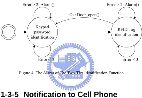
(15) include an RFID reader and keypad whose placement is shown in Figure 2. A user entries the password via keypad for first identification, then second identification is using RFID tags to approach the RFID reader. If the identifications are success then the door would open. The simple state diagram was shown as following.. Error. Error. Keypad enter identification. Ok: Door_open(). RFID Tag identification. Figure 3. The State Diagram of The Two-Tier Identification. The two-tier identification is used to prevent the tags of RFID losing or stealing problems.. 1-3-3 Image Auto Recording Function The entrance system has a camera which grabbing photos anytime from door outside. If something moving is detected by motion detection, then the corresponding function (software) in the system will recode the photos automatically, and store them to a remote server. The reason of store record photos to a remote server is to avoid that the invaders break down the system; consequently, even though the system was broke, the criminal record would store on the remote server.. 1-3-4 Alarm Function The system will invoke an alarm, when it detects the invasion; there are two ways to invoke the alarm: 1. When door was opened without following the normal procedure. Use the tag and enter the password can open the door automatically, if not and the door was opened, than the alarm were enable. Example: the criminals break down the door to entry the house; the criminal uses the 14.
(16) copying key to open the door. 2. When the identification failed three times. If the tag reader program sensed the tag and checked the tag was error three times, or if the password reader program read the keypad and checked the tag was error three times, than the alarm would be invoked. The state diagram was shown in Figure 4. This fundamental is to avoid that the criminals testing the illegal tags or enter passwords many times to attempt to into the house.. Error > 2: Alarm(). Error > 2: Alarm() Ok: Door_open() Keypad password identification. RFID Tag identification. Error < 3. Error < 3. Figure 4. The Alarm of The Two-Tier Identification Function. 1-3-5 Notification to Cell Phone Except the above alarm function will enable when the crime was occurred, the notification will enable too. The notification program will notify the cell phone number of the main members; therefore, main member can get the situation at the first time and take next steps for resisting the criminals. The timing for enabling the notification is when the invasions was detected as above 1-3-4.. 1-3-6 Remote Management Function The main member can use the browser to login the management program of the system for managing the member data and the rights of members. The member data was related with the two-tier identification function, because the identification will read the tag data and password of 15.
(17) the member data for verifying the door opening conditions.. 1-3-7 Remote Monitor Function The member of family can use the browser for watching outside of the entrance via internet any time. The entrance system has a web page for providing images from door outside immediately; hence families can watch it any time.. 1-4 The WiFi Entertainment System 1-4-1 Overview Figure 5 shows the architecture of the WiFi entertainment system.. Media Database E IEE. b .11 802. Play broadcasting MP3. ARM-Based platform. IEE E8 02. 11b. View home albums. Figure 5. The Architecture of The WiFi Entertainment System. The WiFi entertainment system has two part functions— home gallery; 16.
(18) MP3 broadcasting that were described as follows.. 1-4-2 Home Gallery The home gallery is the collection of home digital picture which was obtained from home digital camera. The families can use the browser to see the digital photo in home or internet, and can manage it, such as uploading new photos or deleting existing photos.. 1-4-3 MP3 broadcasting The MP3 was broadcasted by one user, then the music were broadcasting everywhere in home. In this case, the families need to use the media player for playing MP3, such as WinAmp or Quick Time. The browser can play the broadcasting MP3 too, if it invokes the right media player program for playing.. 17.
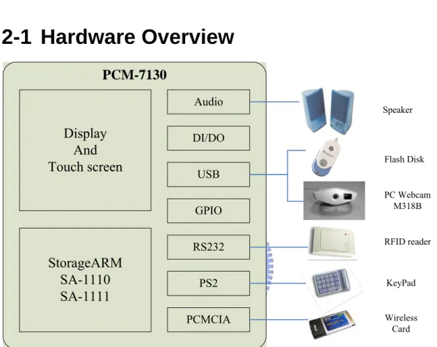
(19) Chapter 2 Implementation of Hardware 2-1 Hardware Overview PCM-7130 Audio. Display And Touch screen. Speaker. DI/DO Flash Disk. USB GPIO RS232. StorageARM SA-1110 SA-1111. PC Webcam M318B. RFID reader. PS2. KeyPad. PCMCIA. Wireless Card. Figure 6. Hardware Overview. 2-2 Arm-based Platform 2-2-1 Overview Figure 7 shows the appearance of Arm-based platform, its name is PCM-7130 embedded system which was produced by ADVANTECH[5]. PCM-7130 includes three main modules which are PCM-7130 single board computer, display module and other inputs/outputs. The I/O of PCM-7130, applied in this thesis, will be described in the following chapters.. 18.
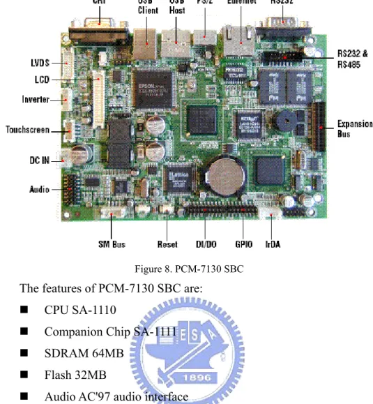
(20) Figure 7. PCM-7130 Embedded System. The introduction and features of PCM-7130 were shows as Chapter 5 .. 2-2-2 PCM-7130 SBC Figure 8 shows the appearance of PCM-7130 SBC. There are many IOs in the PCM-7130 SBC; in this thesis, the applied IOs are, USB Host, PS/2, Ethernet, RS232, General Purpose Input Output (GPIO), DI/DO, Audio, Touch screen, and LCD. In 2-2-4 System I/O would explain what these IO do.. 19.
(21) Figure 8. PCM-7130 SBC. The features of PCM-7130 SBC are: . CPU SA-1110. . Companion Chip SA-1111. . SDRAM 64MB. . Flash 32MB. . Audio AC'97 audio interface. . Buzzer for alarm. . SM Bus Interface. . Embedded Linux X Embedded Linux kernel V.2.4.18 or above X. The Figure 9 shows the block diagram of PCM-7130 SBC.. 20.
(22) Figure 9. The Block Diagram of PCM-7130 SBC. 2-2-3 System Display The system display includes LCD display and touch panel. The LCD display can show: 1. The image streams which are grabbed from the USB camera for the monitoring situation from door outside by user. 2. The graphic user interface (GUI) for setting up the system options. In addition, the touch panel is an input interface for user who can input the commands via the touch panel for controlling the system. The features of the display are: . LCD TTL Interface 18-bit active color LCD/ 16-bit. . LCD LVDS Interface 18-bit LVDS interface. . TouchScreen Interface 4-wire resitive touchscreen interface. . Resolution Up to 800 x 600 @ 16 bpp. 2-2-4 System I/O on SBC The system I/Os of the SBC are very important in this thesis, because 21.
(23) they are the bridge of various devices which described in 2-3. What devices would connect with the IO and what the devices can be used that would be explained as following in brief: . USB Host: This is USB 1.1 version on the SBC, connecting two kinds of devices: USB camera and USB flash disk.. . PS/2: The PS/2 connects with keypad module for entering the password by the users.. . Ethernet: For internet connection, and could be connected with home network. The spec. is 10Mb.. . RS232: The RS232 was applied to connect the RFID module whose demand program would control the RFID module via RS232.. . GPIO: The GPIO of the PCM-7130 can be programmed with interrupt mode. In this thesis, it was applied with the communication between the different processes.. . DI/DO: The pure digital input and digital out was used for debugging and simulating the door open status.. . Audio: For alarm system used.. . PCMCIA slot: Connected the wireless card.. 2-3 Additional Peripherals Except the primary hardware PCM-7130, the RFID module, keypad, USB camera and USB flash disk and PCMCIA wireless card are peripherals in the system. They were described separately in the following chapters.. 2-3-1 RFID Module The RFID full name is Radio frequency identification which is a generic term for technologies that use radio waves, to automatically identify people or objects. There are several methods of identification, but the most common is to store a serial number (ex. UID) that identifies a person or object, and perhaps other information, on a microchip that is attached to an antenna. The antenna enables the chip to transmit the identification information to a reader. The reader converts the radio waves reflected back from the RFID tag, into digital information that can then be passed on to 22.
(24) computers that can make use of it. The appearance of RFID module included three parts in this thesis. They are RFID board, an antenna and RFID tag. The following figures show the appearance of RFID module.. Figure 10. The Appearance of RFID module. 1. RFID board: The RFID board would read the RFID tag, into digital information to host via RS232. The specifications of RFID board in this thesis shows as following: . Frequency : 13.56MHz. . Tag : ISO15693. . Interface : 3-wire ( CMOS,TTL ). . Baud-Rate : 19200, 8, n, 1 (default). . Power Supply : 5V / 200 mA (max). . Standby current : 5V / 300uA. . Operating Temperature :. . Operating Range :. . Mechanical Dimension : 30.0(L) * 28.0(W) * 8.7(H)mm. 0 ~ 60 °C. 6cm (Avg.). 2. Antenna: The more bigger size of antenna can increase the sense distance of the RFID searching the tag, the features are: . Antenna : 50Ω. . Mechanical Dimension : 30.0(L) * 28.0(W) * 8.7(H)mm. 23.
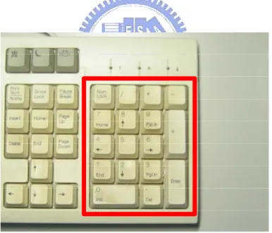
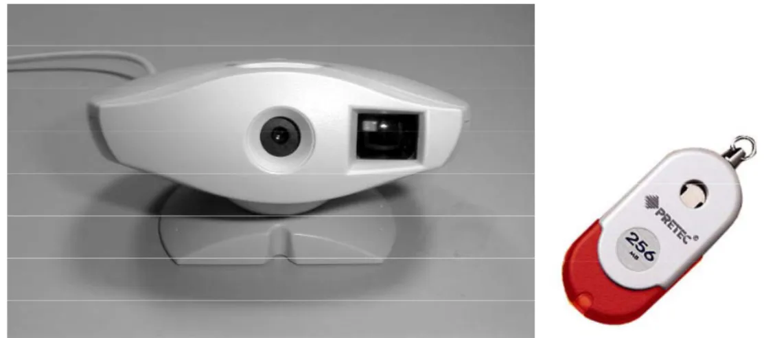
(25) 3. Tag: The tag is compliant with the ISO/IEC 15693 standard. With a user memory of 2k bits, organized in 64 blocks. The specifications of tag are: . Supported Standard ISO 15693-2,-3. . Recommended Operating frequency 13.56 MHz. . Factory programmed Read Only Number (UID) 64 bits. . Memory (user programmable) 2k bits organized in 64 x 32-bit blocks. . Data retention time (at +55°C) > 10 years. . Operating temperature -25°C to +70°C. The application of RFID was, reads the UID of tag and identifies it.. 2-3-2 Keypad The keypad has 9 number keys and an enter key, it was connected with PS/2 on SBC. The purpose of keypad is providing a password input interface for user. The numeric key of PC keyboard was used for simulating a keypad user interface in this thesis. The appearance was shown as following:. Figure 11. The Appearance of Keypad. 2-3-3 USB Camera and Flash Disk The USB flash disk was media storage, such as MP3 music, digital photos, and it is also used for some applications in storage. The USB camera used the M318B USB camera which was a YUV camera. In the software chapter, it would be explained how to make it work. 24.
(26) The following figure shows the appearances.. Figure 12. The Appearance of USB Device. 2-3-4 PCMCIA Wireless Card The DWL-650H Wireless LAN (WLAN) PC Card is a direct-sequence (DS) product. DS is a spread spectrum network operating between 2.4 and 2.5 GHz. The DWL-650H WLAN adapter allows PC Card equipped host systems to configure, connect to and establish a wireless network. The appearance of DWL-650H was shown as following:. Figure 13. The Appearance of DWL-650H. Features Include: . Multiple operating mode options for Access Point (AP) or peer-to-peer (802.11 Ad Hoc) associations with the wired network or other computers. 25.
(27) . Low-power operation for battery-powered devices with PC Card slots.. . Standard NDIS (Network Driver Interface Specification) drivers.. . Card and Socket Services support.. . WEP 40- and 128-bit data security.. . Power management (Continuously Aware Mode (CAM) and Power Save Polling (PSP)).. . In ESS (802.11 Station) mode, the adapter connects to an access point (AP). In ESS mode, the adapter can roam freely between access point cells in the network or transmit and receive across subnets. MUs appear as network nodes to other devices in the network. ESS is the default mode for the adapter.. . Use the IBSS (802.11 Ad Hoc) mode to form peer-to-peer networks without access points. Use IBSS to create networks where needed within established cells. The MU starting the IBSS network (the first WLAN adapter transmitting a beacon) determines the channel and data rate used for the other adapters in the IBSS network.. 26.
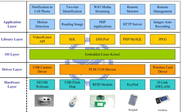
(28) Chapter 3 Implementation of Software 3-1 Overview 3-1-1 Software Overview Notification to Cell Phone. Two-tier Identification. WiFi Media Streaming. Remote Monitor. Remote Management. Application Layer. Motion Detection. Reading Image. PHP Applications. HTTP Server. Images Auto Recording. Library Layer. Video4Linux API. SDL. DSS/Perl. PHP/MySQL. JPEG. Embedded Linux Kernel. OS Layer. Driver Layer. USB Camera Driver. Hardware Layer. M318B Webcam. Wireless Card Driver. PCM-7130 Drivers. USB Flash Disk. RFID Module. KeyPad. D-Link DWL-650. Keypad. wireless. Figure 14. The Overview of Firmware. Figure 14 shows the overview of firmware, which has five layers. The firmware overview, excluded the hardware layer, would be the software overview, and the software overview has four layers: are driver layer; OS layer; library layer and application layer. Bottom layer is the driver layer which has USB camera driver, wireless card driver and PCM-7130 drivers that would be discussed in 3-2-3. The OS layer is embedded Linux kernel which would be discussed in 3-2-1. The library layer provides some API for applications using, it could reduce the 27.
(29) developing times and program size of the applications, and be easily for source management. At last, the top layer is application layer which include all of applications in this thesis, and it would be discussed in later chapters.. 3-1-2 Development Flow Applications Develop Loop. Kernel Develop Loop. Compile ARM Applications. Compile ARM Linux Kernel. Copy The Binary Files of Applications to NFS root Directory. Download Kernel or Ramdisk to PCM-7130 Via RS232. Using cp command in Linux Using UltraEdit or vi Modification or Bug Fix. Using Xmodem in RS232 Terminal Using UltraEdit or vi. Observe the Execution Flow from RS232 Terminal. Using RS232 Terminal to Communicate with PCM-7130. Using RS232 Terminal to Communicate with PCM-7130. Modification or Bug Fix. Success ? No. No Yes. End. Figure 15. The Development Flow. Figure 15 shows the development flow which includes two developing loops, the kernel and applications develop loops. The kernel would be downloading into PCM-7130 after the Linux OS kernel compilation in the kernel developing loop, and the downloading tool was Xmodem tool through RS232 terminal, which can be a super terminal in 28.
(30) Windows or minicom in Linux. The execution flow could be consequently observed from the kernel booting up messages by RS232 terminal which was communicated with the console port on PCM-7130, if the result was subsequently success, then the developing loop would end, if not, then the source code need to be modified or fixed. After the modification was done then go to the compilation step. The other was application loop. The binary files of applications need to copy to NFS (Network File System) root file directory after the applications compilation; the applications could be executed on the embedded system by console port (the 3-2-2 would explain it), and the execution flow could be then observed from the application execution message via RS232 terminal, if the result was success, then the develop loop would end, if not, then the source code need to to modified or fixed. After the modification was done then go to the compilation step.. 3-2 Linux Kernel and Drivers 3-2-1 Linux Kernel, Ramdisk, Bootloader Linux kernel, available for many architectures, is an good candidate for an embedded system, and it already is used widely in this area. Its open nature makes it particularly attractive to developers. The. ADVANTECH. produced. PCM-7130. and. provided. the. corresponding Linux kernel of version 2.4.18-rmk3. The kernel includes important components which are the IO drivers of PCM-7130; therefore, the IO of PCM-7130 could easily to be used by developers. However, the options of Linux kernel still need to be modified, because the original Linux kernel does not enable sufficient IOs. Thus, it would be enabled when the IO requirements the kernel source. This would be discussing in the following chapter. The compilation and running flows of Linux kernel in PCM-7130 is described in this section. . Compiling the Linux kernel z. The Linux kernel need to be compiled after the kernel options was changed or the source code was modified. 29.
(31) z. make zImage: Use this command in Linux (the commands in this section was executed in Linux, except downloading commands) to compile the kernel that would consequently generate ‘kernel.img’ in the /$KernelPath/arch/arm/boot path.. . Maintaining the root file system – Ramdisk z. The ADVANTECH had provided an existing ramdisk, named by ramdisk.gz, therefore, the existing ramdisk only need to maintain not create it.. z. gunzip ramdisk.gz: Use gunzip to uncompress it. The file ramdisk would be then generated.. z. mount -o loop ramdisk /mnt/ramdisk: The contexts of the file, ramdisk, would be mounted in /mnt/ramdisk directory.. z. Maintain the files in /mnt/ramdisk, copy or delete the files in the /mnt/ramdisk directory.. z. gunzip -9 ramdisk.gz: Compress the file ramdisk again. The new ramdisk is generated by this command.. . Downloading the kernel and ramdisk to PCM-7130 z. Use blob bootloader to download the kernel and ramdisk to PCM-7130.. z. Connect the PCM-7130 com1 with PC, and then start a RS232 terminal program in PC, and power up the PCM-7130. The blob message would show on RS232 terminal, then input the following commands in RS232 terminal:. z. xdownload kernel: Use Xmodem protocol to send the kernel.img into the RAM.. z. flash kernel: Write the RAM data into flash ROM.. z. xdownload ramdisk: Use Xmodem protocol to send the ramsidk.gz into the RAM.. z. flash ramdisk: Write the RAM data into flash ROM.. z. boot: Finally, use boot command to booting the Linux kernel following the above commands.. 30.
(32) 3-2-2 NFS (Network File System) The NFS was developed to allow machines to mount a disk partition on a remote machine as if it were on a local hard drive. This allows fast and seamless sharing of files across a network. The installation steps involved are: . Setting up NFS server in Linux z. rpm –ivh nfs-utils-1.0.1-3.9.rpm: Use this command to install.. z. Edit /etc/exports as: (the /mnt/arm-root is the root dir of NFS) /mnt/arm-root PCM-7130_ip(rw,no_root_squash). z . service nfs start: Use this command for starting NFS. Starting NFS in PCM-7130 z. Booting the PCM-7130 first.. z. Configure PCM-7130 TCP/IP network (use ifconfig, route).. z. mkdir /mnt/arm-root: make the mount dir.. z. mount host_ip:/mnt/arm-root /mnt/arm-root: mount the root dir of NFS by Linux.. z. The PCM-7130 can access the /mnt/arm-root which is root dir of NFS in host, i.e. Linux, if no error occurred.. 3-2-3 The Drivers User program. Kernel. Driver. Bus. Controller Device. Software. Hardware. Utility. 31.
(33) Figure 16. Place of a Device Driver in Linux. Figure 16 shows the place of a device driver in Linux relative to the device: . User program or utility: A user program, or utility, makes calls on the kernel but never directly calls a device driver.. . Kernel: The kernel runs in supervisor mode and does not communicate with a device except through calls to a device driver.. . Device driver: A device driver communicates with a device by reading and writing through a bus to peripheral device registers.. . Bus: The bus is the data path between the main processor and the device controller.. . Controller: A controller is a physical interface for controlling one or more devices. A controller connects to a bus.. . Peripheral device: A peripheral device is a device that can be connected to a controller, for example, a disk or tape drive. Other devices (for example, the network) may be integral to the controller Many devices were employed in this thesis that include PCM-7130 IO. devices, USB camera, USB flash disk, keypad, RFID module with RS232, PCMCIA wireless card.; however, the devices need to enable the drivers or add the new drivers in Linux before using these devices. The devices need to be enabled in Linux that is discussed in this section, and the installation of new devices would be discussed as following chapters. The driver must be setting up first when the devices are used, as shown Figure 16. In fact, the drivers are the part of kernel, so we need to adjust some of the kernel option for enabling the drivers.. 3-3 Web Server The web server in PCM-7130 can provide the web base remote monitor, web based remote management, and some entertainment. The structure of web server includes a PHP[6] script and MySQL[7] database. The PHP is used to access MySQL and generals the web pages, and the MySQL can provide a useful database in home, 32.
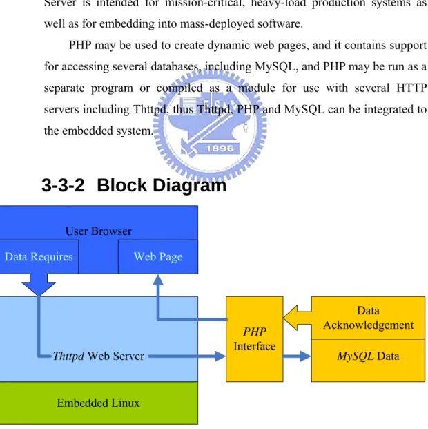
(34) ex. family member data, home photos… etc.. 3-3-1 Thttpd, PHP and MySQL Thttpd[8] is an HTTP server, it has the feature as simple, small, portable and fast, and it is suitable in embedded system. PHP is a widely-used general-purpose scripting language that is especially suited for Web development and can be embedded into HTML. And PHP is a server-side scripting language whose primary purpose is to generate HTML content. The MySQL software delivers a very fast, multi-threaded, multi-user, and robust SQL (Structured Query Language) database server. MySQL Server is intended for mission-critical, heavy-load production systems as well as for embedding into mass-deployed software. PHP may be used to create dynamic web pages, and it contains support for accessing several databases, including MySQL, and PHP may be run as a separate program or compiled as a module for use with several HTTP servers including Thttpd, thus Thttpd, PHP and MySQL can be integrated to the embedded system.. 3-3-2 Block Diagram User Browser Data Requires. Web Page. PHP Interface. Thttpd Web Server. Data Acknowledgement. Embedded Linux Figure 17. Functional Block and Dataflow of Web Server. 33. MySQL Data.
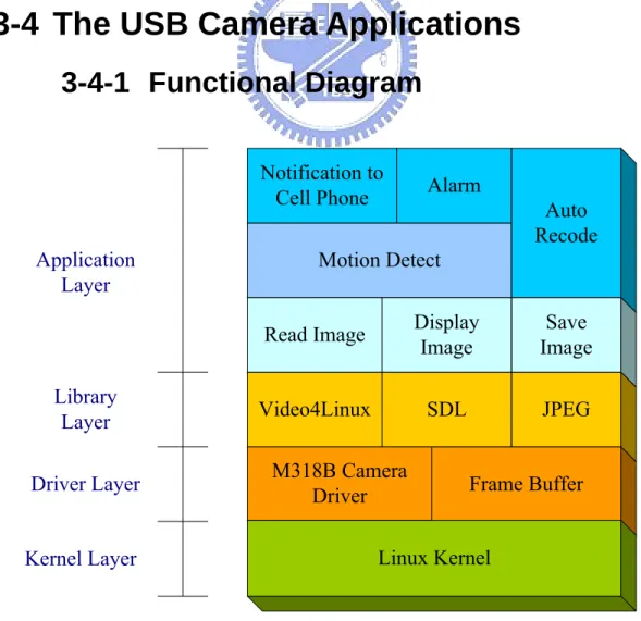
(35) Figure 17 shows the functional block and dataflow of the web server. The functional block has three layers: the bottom layer is embedded Linux which includes driver, kernel and some API; the upper layer is a web server which has three items that are Thttpd, PHP and MySQL; the top layer is a user browser, it may be any web browser, including I.E. or web browser of cell phone. The dataflow for accessing MySQL via a browser is shown as Figure 17; A user uses the web browser for sending the request (as a URL which extension is php) to Thttpd web server which transfers the contents of the web page to PHP interface if the web page of request is php script, PHP then executes the php script, and accesses the database in MySQL that depend on the content in php script, MySQL subsequently returns the data of database to PHP, then PHP can send the web content back to Thttpd, finally, Thttpd sends the web page to the. browser.. 3-4 The USB Camera Applications 3-4-1 Functional Diagram Notification to Cell Phone Application Layer. Library Layer Driver Layer. Alarm Auto Recode. Motion Detect Read Image. Display Image. Save Image. Video4Linux. SDL. JPEG. M318B Camera Driver. Frame Buffer. Linux Kernel. Kernel Layer. 34.
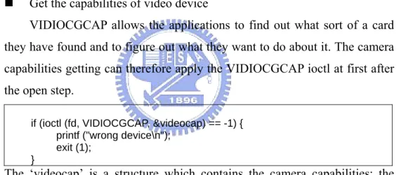
(36) Figure 18. The Functional Block of Camera Applications. Figure 18 shows the functional block of USB camera Applications. This figure has three modes (layers), the bottom mode to up mode are kernel mode, driver mode and application mode respectively. The kernel mode is Linux kernel, the driver mode is the USB driver of M318B camera[9], and the application mode include photo grab, photo display, motion detection and top applications notification to cell phone and alarm. The applications in Figure 18 would be discussed in the following chapters.. 3-4-2 Photo Grab The USB cam grabs photos in Linux need Video4Linux[10], which is intended to provide a common programming interface for the many TVs and capture cards now on the market, as well as parallel port and USB video cameras.. Start. Open the video device. Reading images loop. Get the capabilities of video device. Close the vedio device. Set the channel of video device Stop. Figure 19. Grab photos flow chat. 35.
(37) Figure 19 shows the flow chat of photos grabbing, it has five steps, using the Video4Linux was described as following: . Open the video device: The hardware devices in Linux would be the files, the video device. would be the ‘/dev/video0’ file when the driver started as explained in 3-2-3 . Using the ‘open’ system call which could open the video device for controlling, the C code shows as following: if ((fd = open (“/dev/video0”, O_RDWR)) == -1) { perror ("ERROR opening V4L interface \n"); exit (1); }. The ‘fd’ is the file descriptor in above C code, using this to control the video device. . Get the capabilities of video device VIDIOCGCAP allows the applications to find out what sort of a card. they have found and to figure out what they want to do about it. The camera capabilities getting can therefore apply the VIDIOCGCAP ioctl at first after the open step. if (ioctl (fd, VIDIOCGCAP, &videocap) == -1) { printf ("wrong device\n"); exit (1); }. The ‘videocap’ is a structure which contains the camera capabilities; the Table 1 shows the fields of video_capability Structure:. name. The device text name. This is intended for the user.. channels. The number of different channels you can tune on this card. It could even by zero for a card that has no tuning capability. For our simple FM radio it is 1. An AM/FM radio would report 2.. audios. The number of audio inputs on this device. For our radio there is only one audio input.. minwidth,minheight. The smallest size the card is capable of capturing images in. We set these to zero. Radios do not capture pictures The largest image size the card is capable of capturing. For our radio we report 0. This reports the capabilities of the device, and matches the field we filled in in the struct video_device when registering.. maxwidth,maxheight type. Table 1. video_capability Structure Fields. 36.
(38) . Set the channel of video device The VIDIOCGCHAN ioctl allows a user to ask about video channels.. The M318B has a single camera input. The corresponding VIDIOCSCHAN ioctl allows a user to change channel and to request the norm is changed for example to switch between a PAL or an NTSC format camera. The following C code shows the usage of VIDIOCGCHAN and IDIOCSCHAN. the VIDIOCGCHAN ioctl was call fist to get the videochan structure then using the IDIOCSCHAN ioctl to set the video channel. if (ioctl (fd, VIDIOCGCHAN, &videochan) == -1) { printf ("Hmm did not support Video_channel\n"); isVideoChannel = 0; } videochan.norm = VIDEO_MODE_NTSC; if (ioctl (fd, VIDIOCSCHAN, &videochan) == -1) { printf ("ERROR setting norme \n"); exit (1); }. The fields of video channel structure are: channel The channel number we are selecting name. The name for this channel. This is intended to describe the port to the user Appropriate names are therefore things like "Camera" "SCART input". flags. Channel properties. type. Input type. norm. The current television encoding being used if relevant for this channel.. Table 2. video_channel Structure Fields. . Reading images loop The reading images has two methods as using ‘read’ system call and the. mmap interface, however the mmap interface is faster and it supports the M318B camera, so the mmap was used for reading images in this thesis. To use the mmap interface a user must sets the VIDIOCGMBUF ioctl which reports the size of buffer to mmap and the offset within the buffer for each frame. The number of frames supported is device dependent and may only be one, but the M318B has four frames. The following C code shows the usages of VIDIOCGMBUF ioctl and mmap.. 37.
(39) if (ioctl (fd, VIDIOCGMBUF, &videombuf) < 0) { perror (" init VIDIOCGMBUF FAILED\n"); } pFramebuffer = (unsigned char *) mmap (0, videombuf.size, PROT_READ | PROT_WRITE, MAP_SHARED, fd, 0);. Using VIDIOCGMBUF ioctl to get the structure of videombuf whose structure contents are the following figure, then using the mmap for mapping the video space to processor’s address space. size. The number of bytes to map. frames. The number of frames. offsets. The offset of each frame. Table 3. video_mbuf Structure Fields. . Reading images loop Using the mmap interface to read images for M318B which supports. mmap interface, the following figure shows the steps:. truct video_mbuf Use mmap() for mapping video frame to kernel buffer. Use sync make sure data was ok. Sync frame 2 and capture frame 1. 38. VIDIOCSYNC. VIDIOCMCAPTURE. 6.. VIDIOCSYNC. Application in user space. VIDIOCSYNC. Driver in kernel space. 5.. VIDIOCMCAPTURE. 4.. Let camera do capture photo first. Continue to frame 4 than loop to frame 1. VIDIOCMCAPTURE. Application in user space. mmap(). Driver in kernel space. VIDIOCMCAPTURE. 3.. VIDIOCMCAPTURE. 2.. VIDIOCGMBUF. Driver return 4 frames with video buffer. VIDIOCMCAPTURE. 1..
(40) Figure 20. mmap interface grabs diagram. 1. Get video_mbuf Getting the capabilities of mmap interface is the first thing before using it that was discussed as above. 2. Use mmap() Use the mmap for mapping the video device frames buffers to the kernel buffer which is a big buffer containing video frames, the process address buffer can therefore read the images directly. 3. Capture image Once the mmap has been made the VIDIOCMCAPTURE ioctl starts the capture to a frame using the format and image size specified in the video_mmap (which should the same with or small than the initial query size). When the VIDIOCMCAPTURE ioctl returns the frame is not captured yet, the driver just instructed the hardware to start the capture. The application has to use the VIDIOCSYNC ioctl to wait until the capture of a frame is finished. It is allowed to call VIDIOCMCAPTURE multiple times (with different frame numbers in video_mmap->frame of course) and using VIDIOCSYNC ioctl to sync the images. The four VIDIOCMCAPTURE is issued for capturing the images with the hardware in this step. 1. Sync image until return to process Use. the. VIDIOCSYNC. ioctl. to. video. device. after. VIDIOCMCAPTURE ioctl, the image is ready when the VIDIOCSYNC ioctl returns, the image can then be processed. 2. Sync frame 2 and Capture frame 1 The. video. frame. 1. of. hardware. can. be. issued. with. VIDIOCMCAPTURE ioctl again after the VIDIOCSYNC ioctl of frame 1. The frame 2 can be subsequently used VIDIOCSYNC ioctl for waiting the image ready after the previous frame (frame 1) was processed. 3. Continue to frame 4 than loop to frame 1. 39.
(41) CAPTURE CAPTURE CAPTURE CAPTURE. frame 1 frame 2 frame 3 frame 4. Process frame 2. Process frame 1 SYNC frame 1. CAPTURE frame 1. SYNC frame 2. CAPTURE frame 2. CAPTURE frame 4. SYNC frame 4. CAPTURE frame 3. SYNC frame 3. Process frame 4. Process frame 3. Figure 21. Reading Image Loop. Figure 21 shows the reading image loop. The loop would start after capture all frames, then executing the same procedure that VIDIOCSYNC and and VIDIOCMCAPTURE process with the frame 1 until frame 4 than loop back to frame 1. How to process these frames would be discussed as below.. 3-4-3 Images Display. 40.
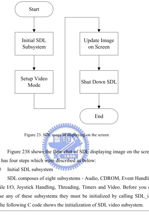
(42) Figure 22. SDL interface flow chat. Displaying the images on the screen (LCD display) is the first thing to do after the image was read. The displaying tools is applied with SDL[11] (Simple DirectMedia Layer) interface (APIs) which is shown in Figure 22, SDL is a cross-platform multimedia library designed to provide low-level access to audio, keyboard, mouse, joystick, 3D hardware via OpenGL, and 2D video framebuffer. The video device driver supports a framebuffer device in Linux kernal, so a user can easily use SDL API for displaying image on LCD screen for using framebuffer .. 41.
(43) Start. Initial SDL Subsystem. Update Image on Screen. Setup Video Mode. Shut Down SDL. End Figure 23. SDL usage of displaying on the screen. Figure 238 shows the flow chat of SDL displaying image on the screen, it has four steps which were described as below: . Initial SDL subsystem SDL composes of eight subsystems - Audio, CDROM, Event Handling,. File I/O, Joystick Handling, Threading, Timers and Video. Before you can use any of these subsystems they must be initialized by calling SDL_init. The following C code shows the initialization of SDL video subsystem. if ((SDL_Init (SDL_INIT_VIDEO) == -1)) { printf ("Could not initialize SDL: %s.\n", SDL_GetError ()); exit (-1); }. The parameter specifies are: SDL_INIT_VIDEO. Initializes the video subsystem.. SDL_INIT_TIMER. Initializes the timer subsystem.. SDL_INIT_AUDIO. Initializes the audio subsystem.. SDL_INIT_CDROM. Initializes the cdrom subsystem.. SDL_INIT_JOYSTICK. Initializes the joystick subsystem. SDL_INIT_EVERYTHING. Initialize all of the above.. SDL_INIT_NOPARACHUTE Prevents SDL from catching fatal signals.. 42.
(44) SDL_INIT_EVENTTHREAD. Initializes the event thread.. Table 4. SDL_Init flags. . Setup Video Mode Use SDL_SetVideoMode to set up a video mode with the specified. width, height and bits-per-pixel. The following C code shows the usage of SDL_SetVideoMode, which would return a pointer of SDL_Surface structure, the image can then be filled into the pointer pscreen->pixels. The parameter are width, height, bpp and flags, the width and height parameters are the specific of the video, the bpp parameter is the number of bits per pixel, so a bpp of 24 uses the packed representation of 3 bytes/pixel., and the flags parameters are show in Table 5. pscreen = SDL_SetVideoMode (image_width, image_height, 24 , SDL_SWSURFACE); if (pscreen == NULL) { printf ("Couldn't set %d*%dx%d video mode: %s\n", image_width, image_height, bpp * 8, SDL_GetError ()); exit (1); } SDL_SWSURFACE Create the video surface in system memory SDL_HWSURFACE Create the video surface in video memory SDL_ASYNCBLIT. Enables the use of asynchronous updates of the display surface. SDL_ANYFORMAT Normally, if a video surface of the requested bits-per-pixel (bpp) is not available, SDL will emulate one with a shadow surface. Passing SDL_ANYFORMAT prevents this and causes SDL to use the video surface, regardless of its pixel depth. etc …. etc …. Table 5. The SDL_SetVideoMode flags parameters. . Update Image on Screen Use SDL_UpdateRect to makes sure the given area is updated on the. given screen. The rectangle must be confined within the screen boundaries. The SDL_UpdateRect parameters are pscreen, x, y, w, h, if x, y, w and h are all 0, SDL_UpdateRect will update the entire screen. The C code shows 43.
(45) the usage of SDL_UpdateRect as following: SDL_UpdateRect (pscreen, 0, 0, 0, 0);. . Shut down SDL Use SDL_Quit to shut down SDL. SDL_Quit ();. 3-4-4 Motion Detection The motion detection is referenced with PHPMotionDetect[12], the motion detection is on, if the grabbed image is different than the previous image. Then some applications in top layer would be issued if the motion detection is on, ex. auto recorder, notification. The following figure and article was described in more detail:. time Image 5. Image 4. Image3. MAD (3,4). Image2. Image 1. MAD (1,2). If ( |MAD1 - threshold|>1 ) and ( |MAD2 - threshold| > 1 ) then Motion Detected !! Figure 24. Motion Detection with Double Difference. Figure 24 shows the motion detection with double difference, the double difference is to prevent the error motion detection occurs with the error image, because the M318B sometime grabbed error images. Using MAD[13] (mean absolute difference) formula calculates the variance of image1 with image2, show as following:. 44.
(46) MAD =. 1 N. ∑∑ S ( x, y ) − S 1. y. 2. ( x, y ). x. The x, y are the row and column which is a pointer of dot in the image, the N is total dots in the image, the S1 and S2 are image1 and image2, therefore the MAD is the sum of the difference of every dot in image to divide the total dots in the image. The motion detection occurs with four frames around, if the 12 images grabbed in 1 second by M318B, the motion detection then occurs 3 times per second. (The M318B grabs 11 images per sec.) .. No. Wait Difference. No. Yes. Wait Two-times Difference. Yes. NO. Motion Detection. Yes. Figure 25. The State Diagram of Motion Detection. Figure 25 shows the state diagram of motion detection, it has three states which are: . State 1 : Wait Difference The difference is occurred, if the absolute value of MAD is bigger than. 1, this value was obtained from the characteristic of M318B webcam whose MAD is sometimes not stable in some static frames. If the difference was not occurred then the state would not change else the state would change to the Double Difference stat. . State 2 : Double Difference The double difference means the difference continuous occurs twice. that can avoid the grabbing image has error. If the double difference not occurs, then back to state 1, or go to next state. In the other hand although the motion detection need more two images to decide it, it only spends 1/3 sec. in reasonable time. . State 3 : Motion Detection This state was keep by the motion detection, if motion does not be 45.
(47) detected than the state changes to state 1.. 3-4-5 Image Auto Recording The motion images would be recorded to the remote server, when the motion detection occurred. The reason of recording motion images to the remote server is to prevent the inventors break down the system.. Figure 26. Conceptual Client/Server Model. Figure 26 presents a simple client/server model. Client/Server model is a concept for describing communications between computing processes that are classified as service consumers (clients) and service providers (servers). Each client/server relationship is established between two functional modules when one module (client) initiates a service request and the other (server) chooses to respond to the service request. Examples of service requests (SRs) are "Upload the JPEG files" "Streaming the image data" etc. For a given service request, clients and servers do not reverse roles i.e., a client stays a client and a server stays a server. The client/server model was implemented in the record server. The server side is PC base computer which used Linux OS to simulate the remote server, the client side is PCM-7130, a server program and client program are in Linux and PCM-7130 respectively as shown in Figure 26. Table 6 presents the communication commands with the server and 46.
(48) client.. Server Response Commands. Client Request Commands. LOGIN. TYPE. PASSWORD. Image types: JPG, YUV, AVI …. OK. SIZE. ERROR Massage. STREAMING. BYE. QUIT. Table 6 Client/Server Commands. . Server Response Commands z. LOGIN, PASSWORD: These commands are for identifying the login user. If login user was wrong, then the server would break the connection.. z. OK: Responses the client request command was okay.. z. ERROR Massage: Responses the client request command was error, and the reason.. z . BYE: Responses the ‘QUIT’ command of client.. Client Request Commands z. TYPE: Requests the file type for record data with the server.. z. Image types: The image types are jpg, yuv, avi…etc. The client can send the image type commands (JPG, YUV, AVI…etc.) to server after ‘TYPE’ command. This command would decision the saving type in the record server.. z. SIZE: The size of record data can be send before streaming the record data. After this command the record data size can be send with client.. z. STREAMING: This command tells the server the record data has been ready to send, after response command ‘OK’ replied form server, the client can send the record data to server.. z. QUIT: Closes the connection by client.. 47.
(49) Linux. PCM-7130. Linux. PCM-7130. Record Server. Record Client. Record Server. Record Client. Request Response. AMING Request cmd: STRE Response data: OK. Request Response. Record Data Record Data. Figure 27. The Commands Communication. The following Figure 27 illustrates the communication of the server and the client with the commands. The request/response commands are the communication system in this client/server model. In this model, the server would response the ‘OK’ or ‘ERROR massage’ by every request command is issued of the client. The client would continue sending the record data to the server until recording stop, after the client issued the ‘STREAMING’ request command and the ‘OK’ command by the server response when the record server identified the login user and the client initialed the record server.. Linux 5 FFMPEG . Recorded Video (.3gp). PCM-7130 JPEG stream. JPEG stream. 4 .. 3 .. 1. login. Record Server. Record Client. Socket. Socket. TCP/IP. TCP/IP. Low layer. Low layer Internet. Figure 28. The Record Server and Client Diagram. 48. 2 .. YUV stream.
(50) Figure 28 illustrates the record client (PCM-7130) and a record server (Linux) using the TCP/IP protocol stack. The client and server each interact with a protocol in the socket layer of the stack. The procedure of the client images saving to record server when auto recode is issued. 1. The client process logins on the record server The client first connects to record server program using socket interface, the server subsequently identifies the client rights that responses the ‘Login’ and ‘Password’ command to the client, if the username and password are correct whose the client sent then the server identify is okay or the server would break down the connection. 2. YUV convert to JPEG in client The first image type is YUV cause of the M318B camera, and the file size is too bigger for YUV image to send. The YUV image files therefore need to reduce size with compressed, hence the compressed image has many file type, ex. avi, mpg, jpg … etc, and the jpg encoder is wonder for the others as the compressive performance of PCM-7130. PCM-7130 applied jpeg encoder with JPEG Group’s ‘jpeglib’ which is ISO JPEG standard and more convenient to use. 3. The client process sends the jpeg stream to the record server The client process would send the jpeg stream to record server after the jpeg image file is ready, if the client process wants to finish the streaming, then it can sent ‘Quit’ command or break down connection by directly. 4. The server stores the jpeg stream The server process gets the jpeg stream from the client via internet, the server then save the jpeg files in a directory and make a sequent name with its. 5. JPEG convert to 3gp (third generation video) format video file to FTP directory using FFmpeg The server would back to listen mode for waiting the connection with client when the connection is broke, in the same time the server invokes the FFmpeg program in background to encode the jpeg stream (which obtained by step 4) to a video file for the users watching it. FFmpeg is a very fast video and audio converter, and it supports many video and audio codec. The 49.
(51) FFmpeg make the jpeg stream to video file with 3gp format for suiting in cell phone. Using the following execution to encode jpeg stream to 3gp video format: ffmpeg –r 11 –i /jpeg_src_dir/%05img.jpg –vcodec mpeg4 /ftp_dir/name.3gp. The options: z. -r rate: set the frame rate. z. -i filename: input file name. z. -vcodec codec: force video codec. z. last parameter: output file name. 3gp is the third generation video standard. It is a file format specially developed for hird generation mobile devices. It is based on the MP4 file format.. 3-4-6 Notification to Cell Photo. Figure 29. Notification to Cell Photo System. Figure 29 presents the system of notification to call photo, the PCM-7130 sent the cell phone number and the short massage to TwSMS[14] Company via internet. The SMS server in TwSMS processed the data from 50.
(52) PCM-7130 then sent the SMS to cell phone. TwSMS is a SMS sending company in TW. It provides many methods for sending SMS to cell phone by user. Those methods are web interface, mail to SMS and API interface which includes PHP, perl, Java, JSP and ASP. The PCM-7130 used the PHP to send the SMS to cell phone via TwSMS in this thesis.. SMS Platform Send SMS. 4.. PCM-7130 PHP Script. TW-SMS 3.. 2.. HTTP. HTTP. TCP/IP. TCP/IP. Low layer. Low layer. 1.. User name: Password: Phone Number: Massage:. Internet Figure 30. The SMS Sending Diagram. Figure 30 illustrates the SMS sending system using the TCP/IP protocol stack in this thesis. Edit the sms.php file: The sms.php is a php script file of SMS sending that provided by TwSMS. The file need to edit before below steps and it includes four important parameters, which are: z. Username: Registered username on TwSMS web page. Using the php API to send the SMS need this username which is registered on TwSMS web page.. z. Password: The password is registered with username as above.. z. Phone Number: The cell phone number for sending SMS.. z. Massage: The massage for sending SMS, the size is limit at 160 chars. 51.
(53) 1. Execute PHP script for sending SMS via HTTP: The PHP script (sms.php) uses HTTP protocol to send the SMS data to 2. TwSMS http server. Execute the php script: z. php sms.php: This command would invoke the php to execute the content of sms.php.. 3. TwSMS receives the SMS from PCM-7130 via internet: TwSMS may receive the PCM-7130 SMS data if step 2 had been success. 4. Send The SMS to cell phone by TwSMS The SMS is queued in the SMS platform after receive the SMS data, the SMS would send to cell phone when the system were non-busy. The following figure shows the detail with the SMS sending flow.. Application (PHP/ASP/JSP/ JAVA/Other). Browse (IE / Netscape / Other). HTTP/SMTP/FTP/ SOCKET. Web Server. Input Queue. TwSMS Service Platform. Output Queue DB. Operator (TCC/TAT/FET/KGT/CHT/PHS/APBW/MOBITAI). 52.
數據
+7
Outline
相關文件
[This function is named after the electrical engineer Oliver Heaviside (1850–1925) and can be used to describe an electric current that is switched on at time t = 0.] Its graph
• The ArrayList class is an example of a collection class. • Starting with version 5.0, Java has added a new kind of for loop called a for each
• To introduce the use of the LPF as a tool for planning the school English Language curriculum; and
Understanding and inferring information, ideas, feelings and opinions in a range of texts with some degree of complexity, using and integrating a small range of reading
Promote project learning, mathematical modeling, and problem-based learning to strengthen the ability to integrate and apply knowledge and skills, and make. calculated
Students are asked to collect information (including materials from books, pamphlet from Environmental Protection Department...etc.) of the possible effects of pollution on our
The TRG consists of two components: a basic component which is an annual recurrent cash grant provided to schools for the appointment of supply teachers to cover approved
For the proposed algorithm, we establish a global convergence estimate in terms of the objective value, and moreover present a dual application to the standard SCLP, which leads to
For the proposed algorithm, we establish its convergence properties, and also present a dual application to the SCLP, leading to an exponential multiplier method which is shown
