國
立
交
通
大
學
資訊科學與工程研究所
碩
士
論
文
無線感測網路下基於所在房間位置
之高效率室內定位技術
An Efficient Room-based Indoor Localization Scheme
for Wireless Sensor Networks
研 究 生:邱奕銘
指導教授:王國禎 博士
無線感測網路下基於所在房間位置
之高效率室內定位技術
An Efficient Room-based Indoor Localization Scheme for
Wireless Sensor Networks
研 究 生:邱奕銘 Student:Yi-Ming Chiu
指導教授:王國禎 Advisor:Kuochen Wang
國 立 交 通 大 學
資 訊 科 學 與 工 程 研 究 所
碩 士 論 文
A ThesisSubmitted to Institutes of Computer Science and Engineering Department of Computer Science
National Chiao Tung University in Partial Fulfillment of the Requirements
for the Degree of Master
in Computer Sciencmae June 2009
Hsinchu, Taiwan, Republic of China
無線感測網路下基於所在房間位置
之高效率室內定位技術
學生:邱奕銘 指導教授:王國禎 博士
國立交通大學資訊科學與工程研究所
摘 要
隨著無線網路及超大型積體電路技術的快速發展,有更多的無線感測網
路應用,如利用無線感測網路來提供病患的位置資訊,以協助醫療照護就
是很好的例子。在室內的環境中,提供所在房間位置資訊比提供位置座標
資訊更有參考價值。雖然目前基於訊號強度之定位演算法可達到不錯的準
確度,但其利用座標資訊直接轉換為房間資訊卻常有一定程度的誤差。在
本論文中,我們提出在無線感測網路下基於所在房間位置之高效率室內定
位技術,其主要目標為提供高準確率之房間定位資訊以及降低演算法的計
算成本。本研究藉由地圖資訊,限制標地物可移動的位置,並結合以座標
i資訊為基礎之特徵值比對演算法來減少無線網路多重路徑訊號影響所造成
房間位置資訊的誤判,並降低定位誤差。實驗結果顯示,在RADAR定位系統
上應用我們的方法可以將房間資訊的定位準確度自69% 提升到94%,並且將
定位誤差由3.19公尺降低為2.24公尺。我們也與以提供房間位置資訊的定
位演算法Signpost做比較,實驗結果顯示雖然我們的方法會比Signpost多
了一秒的定位延遲時間,但在各種的干擾環境下,我們的房間資訊的定位
準確度比Signpost增加20%。
關鍵詞:室內、定位技術、無線感測網路、房間資訊。
An Efficient Room-based Indoor Localization
Scheme for Wireless Sensor Networks
Student:Yi-Ming Chiu Advisor:Dr. Kuochen Wang
Department of Computer Science National Chiao Tung University
Abstract
With rapid advances in wireless and VLSI technologies, applications of wireless sensor networks (WSN), such as target localization in medical environments, are getting more and more popular. In an indoor environment, identifying a target in a logical area, such as a room is more meaningful than identifying a location represented by coordinates. In existing indoor localization algorithms, although their average location estimate errors may be low, they may not provide high accuracy room-level information, which is usually transformed from the predicted coordinates obtained by their localization algorithms. In this thesis, we present a room-based indoor localization scheme using a path-restricted room-level localization algorithm (PRLA) and a fingerprinting based technique for wireless sensor networks. The design of the proposed PRLA localization system meets two objectives. The first is high accuracy of room-level localization and the other is low computational overhead. Experimental results show that by applying our PRLA scheme to the RADAR system, it significantly improves its room-level hit rate from 69% to 94% and reduces the average error distance from 3.19 m to 2.24 m. In addition, the proposed PRLA scheme can be applied to any coordinate-based indoor location system to enhance its room-level hit rate and localization accuracy. We also compared the proposed PRLA with Signpost which is also a room-based
localization scheme. Experimental results demonstrate that the delay time to enter a room of the proposed PRLA was one second more than that of Signpost; however the proposed PRLA is more reliable than Signpost because its average room-level hit rate is 20% better than Signpost’s in our experiment when we move around in the same room.
Acknowledgements
Many people have helped me with this thesis. I am in debt of gratitude to my thesis advisor, Dr. Kuochen Wang, for his intensive advice and guidance. I would also like to show my appreciation for all the classmates in the Mobile Computing and Broadband Networking Laboratory for their invaluable assistance and inspirations. The support by the National Science Council under Grant NSC 97-3114-E-009-001 is also gratefully acknowledged. Finally, I thank my father, my mother and my friends for their endless love and support.
Contents
Abstract (in Chinese)……….………...i
Abstract (in English) ... iii
Contents ... vi
List of Figures ... viii
List of Tables ... ix
Chapter 1 Introduction ... 1
1.1 Motivation ... 1
1.2 Research objective ... 2
1.3 Thesis organization ... 2
Chapter 2 Related Work ... 4
2.1 Room-level localization system ... 4
2.2 Qualitative comparison of existing indoor localization approaches ... 4
Chapter 3 Proposed Room-based Localization Scheme ... 8
3.1 Architecture of the proposed localization system ... 8
3.2 Off-line phase... 8
3.2.1 Fingerprints buildup………..…8
3.2.2 Fingerprints partition ... 9
3.2.3 Path-restricted information buildup ... 9
3.3 On-line phase ... 11
3.3.1 Room-level localization ... 12
3.3.2 Localization estimator ... 12
Chapter 4 Experimental Results and Discussion ... 16
4.2 Experimental results ... 18 Chapter 5 Conclusions ... 23 5.1 Concluding remarks ... 23 5.2 Future work ... 23 Bibliography ... 24 vii
List of Figures
Figure 1. Localization problem. ... 2
Figure 2. Main idea of Signpost. ... 5
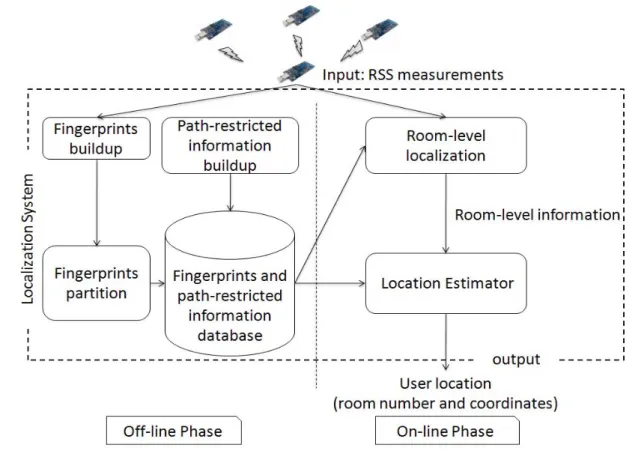
Figure 3. Architecture of the proposed localization system. ... 9
Figure 4. An example floor layout. ... 11
Figure 5. Path-restricted block diagram of Figure 4. ... 11
Figure 6. The flowchart of room-level localization algorithm. ... 14
Figure 7. Room-level localization algorithm ... 15
Figure 8. Testbed setup ... 17
Figure 9. Octopus II sensor node [4]. ... 17
Figure 10. Room-level hit rate versus number of anchor nodes ... 20
Figure 11. Comparison of the 25th, 50th, 75th percentile values and the average error distance. ... 20
Figure 12. Walking path of test environment 1 ... 21
Figure 13. CDF of delay time to enter Room4 ... 21
Figure 14. Walking paths of test environment 2 ... 22
ix
List of Tables
Table 1. Qualitative comparison of existing indoor localization schemes ... 7 Table 2. Signal strength information ... 10
Chapter 1
Introduction
1.1 Motivation
A wireless sensor network (WSN) is composed of a large number of sensor nodes used to sense data from some interesting areas or targets [15] [16]. This type of networks is becoming cheap and has low power consumption. In recent years, localization systems using WSN for military and homecare applications are getting more and more popular. In outdoor environments, the global positioning system (GPS) [2] is a feasible solution for localization. However, equipping GPS receivers to a large scale WSN is not a cost effective solution in most applications and the GPS receiver may compute locations incorrectly in indoor environments because its signals are line-of-sight (LOS). For indoors, most existing localization algorithms using wireless signals such as GSM [23] or Wi-Fi [1] can hardly achieve a reasonable localization precision due to the multipath effects caused by the indoor space’s complexity [6].
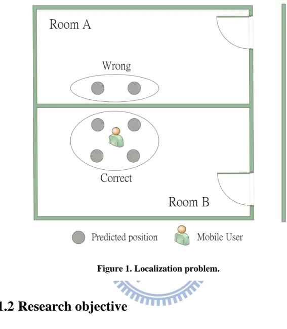
A crucial problem that these algorithms will suffer is that they will make erroneous judgements when the user is approaching a wall. As shown in Figure 1, as the user stands close to the wall, the predicted position obtained by the localization system may be one of the gray dots around the user. If the room-level information is transformed from the predicted position, it may make an erroneous judgement when the gray dot is not in the same room as the user’s. The reason is that wireless signals are easy to suffer from interferences, such as people moving around the sensors [25]. Such interferences make wireless signals vary in a short period and affect the predicted position from one room to another. Our goal is to determine the correct room that the user is in and enhance the localization accuracy.
Figure 1. Localization problem.
1.2 Research objective
In this thesis, we propose a path-restricted room-level localization algorithm (PRLA) to identify a logical area, such as a room, where the user is located, instead of transforming from the predicted position directly. We also apply our proposed PRLA to the RADAR system which is a coordinate-based algorithm in order to enhance its localization accuracy and room-level hit rate.
1.3 Thesis organization
The rest of this thesis is organized as follows. In Chapter 2, we survey related work on indoor localization. In Chapter 3, we describe our design approach in detail. Chapter 4
presents the testbed setup and discusses experimental results. Conclusions and future work are discussed in Chapter 5.
Chapter 2
Related Work
2.1 Room-level localization system
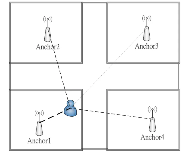
In recent past, many localization systems have tried to solve the problems of location estimation and object tracking using different wireless technologies such as wireless local area networks (WLAN) [17] [18], wireless sensor networks (WSN) [5] [10] [19] and GSM [20]. The indoor room localization estimation (Signpost) [12] is based on wireless sensor networks, using a wireless personal area network (WPAN) standard Zigbee. It is a room-based localization scheme to provide room-level localization information. For example “Mary is in room1.” The author considered the behaviors of the received signal strength (RSS) measurements around walls, doors and other obstacles. In Figure 2, we can see that the signal strength for the link between the user and anchor1 is stronger than that of any other link. The main idea of Signpost is to select an anchor with the strongest RSS. Each anchor is associated with a room. However, sometimes an erroneous room indication may occur when the user is located close to a wall.
2.2 Qualitative comparison of existing indoor localization
approaches
As shown in Table 1, we briefly describe some existing indoor localization approaches. In [6], it uses spatial connective information to filter out distorted messages and uses a simplified weighted coordinate-center of gravity localization method to calculate mobile node coordinates. Experimental result showed the average error distance is 2.6 m, but the author
mentioned that this method had a problem of lower precision positioning in the marginal position.
Figure 2. Main idea of Signpost.
HIS2 [7] is used to monitor a patient’s activity. It uses different types of IR sensors and
presents a decision algorithm to identify which room the user is located. This method cannot get the real coordinates of a user. It can only provide a symbolic location. A symbolic location is an abstract description of an object’s location. It can refer to a place or person. For example, “Mary is in front of the desk.”
There are two kinds of fingerprinting techniques. One is a deterministic method and the other is a probabilistic method. The deterministic method utilizes only current collected sensing data and applies a deterministic inferences to estimates a target’s location. The
probabilistic method calculates the appearance probability of the current RSS measurement for a user. If a location has a maximum probability, it will be the predicted position where the user is located [24].
The Horus system [13] [14] is based on wireless LANs, using the IEEE 802.11 standard. It is a probabilistic fingerprinting localization system. The autocorrelation between consecutive samples from the same access point can be as high as 0.9, since it can adjust the RSS from each access point. It is a method that takes high autocorrelation into account to achieve high accuracy. Its average error distance can be down to 2 m [14].
Delaunay Triangulation [8] is a geometric method for determine triangular vertices. In [8], a mobile sensor node records the packet delivery ratios from a set of static nodes and forms a set of Delaunay triangles. Then it chooses a most likely one to provide a boundary and calculate the mobile sensor node’s location.
The most widely used localization technique in indoor wireless networks is fingerprinting [3]. This technique is superior to other indoor localization techniques such as triangulation [3]. The fingerprinting technique has the abilities to deal with specific indoor environment problems such as non-line-of-sight (NLOS) and multi-path propagation conditions. The most referenced localization approach is RADAR [1] [11]. Its localization algorithm is called nearest neighbor in signal space (NNSS). The mobile device collects the RSS measurements from a set of access points during the offline phase and then calculates the most likely training point to be the predicted position that the user is located during the online phase. The average error distance of the NNSS algorithm is 3-5 m [1].
In this thesis, we present a room-based indoor localization scheme using a path-restricted room-level localization algorithm (PRLA) and a fingerprinting based technique for wireless sensor networks. The details of the design approach are presented in next chapter.
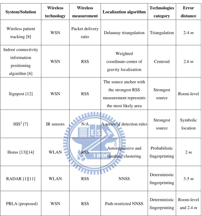
Table 1. Qualitative comparison of existing indoor localization schemes
System/Solution Wireless
technology
Wireless
measurement Localization algorithm
Technologies category Error distance Wireless patient tracking [8] WSN Packet delivery
ratio Delaunay triangulation Triangulation 2-4 m Indoor connectivity information positioning algorithm [6] WSN RSS Weighted coordinate-center of gravity localization Centroid 2.6 m Signpost [12] WSN RSS
The source anchor with the strongest RSS measurement represents
the most likely area
Strongest
source Room-level
HIS2 [7] IR sensors N/A A series of detection rules Strongest source
Symbolic location
Horus [13][14] WLAN RSS Autoregressive and database clustering
Probabilistic
fingerprinting 2 m
RADAR [1][11] WLAN RSS NNSS Deterministic
fingerprinting 3-5 m
PRLA (proposed) WSN RSS Path-restricted NNSS Deterministic fingerprinting
Room-level and 2.4 m
Chapter 3
Proposed Room-based Localization
Scheme
3.1 Architecture of the proposed localization system
The architecture of the proposed localization system is shown in Figure 3. The most important hardware requirement of our approach is only to put a sensor node as an anchor in each area. We don’t need any navigator like GPS or other hardware like RFID. This makes our localization system more cost effective. Our localization system can be divided into two phases: off-line phase and on-line phase.
3.2 Off-line phase
The main tasks in the off-line phase are building up a fingerprints database, constructing path-restricted information from the map, and partitioning the fingerprints database according to the map information.
3.2.1 Fingerprints buildup
We use a laptop equipped with a sensor node to collect RSS measurements received from each anchor node. The sensor collects RSS measurements in each direction (North, East, South, and West) at every training point and sends them to the fingerprints database. We records 100 samples of the RSS measurements received from each anchor node and compute the sample mean that corresponding to each anchor node in each direction.
Figure 3. Architecture of the proposed localization system.
3.2.2 Fingerprints partition
In this stage, we add the room number of the corresponding training point. We then record the data in the database in a form shown in Table 2, where x and y are the coordinates of a training point. The Room number represents which room the training point located. D is the direction, which indicates a direction (N, E, S, or W). The rest of the fields are the sample means of RSS measurements obtained from each anchor node in the fingerprints buildup stage.
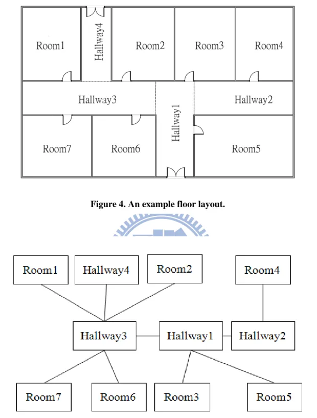
3.2.3 Path-restricted information buildup
The main idea of the path-restricted information is based on the basic ray-tracing algorithm in [22]. The purpose of the path-restricted information is to restrict the target to move to certain logical areas where it can be. In this way, we can filter out the RSS from an anchor such that there is no path from the target to the room that the anchor is located. This
can make the room-level information more accurate in the on-line phase. In order to provide path-restricted information in the on-line phase, we first construct a path-restricted block diagram corresponding to a floor layout. Figure 4 and Figure 5 show an example. The path-restricted block diagram is a topology which consists of a set of blocks and edges. A block represents a logical area, such as a room. If two blocks connected by an edge, it means that we can move from one block to another and vise versa. After data preprocessing in the off-line phase, all sensed data are stored in a database.
Table 2. Signal strength information
Coordinates ( x , y )
Room
number D
Received signal strength (RSS)
Anchor1 Anchor2 … Anchorn
1 1 1 N -48 -33 -22 1 2 2 S -10 9 -26 . . . . . . . . . . . . . . . . . . . . . 12 33 9 E 12 -47 -39
D = direction, N = north, S = south, E = east, W = west
Figure 4. An example floor layout.
Figure 5. Path-restricted block diagram of Figure 4.
3.3 On-line phase
The main tasks in the on-line phase are to determine which room the target is located and estimate the target’s location based on the RSS measurements from each anchor node.
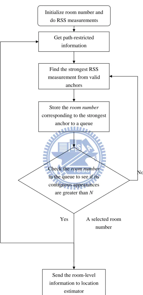
3.3.1 Room-level localization
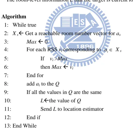
Here, we describe our room-level localization algorithm. The flowchart is shown in Figure 6 and the room-level localization algorithm in pseudo code is given in Figure 7. The inputs of this stage are the RSS measurements received from each anchor node and an initial room number. The output is the room-level information. It could be an area (e.g., a hallway or a room). As shown in Figure 7, in line 2, we find valid room numbers that the target can move to corresponding to the initial room number or the previous room number from the path-restricted information that has been constructed in the off-line phase. In line 4-8, we will only compare the RSS measurements corresponding to the valid room numbers found in the previous step and choose the room number where an anchor with the maximum signal is located. Then, we save the room number corresponding to the chosen anchor node into the queue of size n. Finally, we will check the room numbers in the queue to see if these room numbers are the same. If the same room numbers repeat in the queue for n times, then this room number is the current room number of the target and the number will be send to the localization estimator.
3.3.2 Location estimator
The location estimator is used to calculate a target location based on RADAR [1]. We use the nearest neighbor in signal space (NNSS) algorithm to select the location from the partial database that best matches the observed RSS measurements, which corresponds to the room number obtained from the room-level localization algorithm. By this method, we can reduce computation overhead. If there are more rooms in the map, our method have lower computation overhead.
In order to select the location that best matches the observed RSS measurements, we compute the distance between the unknown position target and each stored location in the database using the Euclidean distance (1) measure,
(
)
(
)
...
(
)
(1)
2 , 2 2 , 2 2 1 , 1 n n iss
ss
ss
ss
ss
ss
d
=
−
+
−
+
+
−
where n is the number of anchor nodes. The vector (ss1, ss2, …, ssn) is the average RSS
measurements stored in the database and (ss’1, ss’2… ss’n) represents the RSS measurements
collected from each anchor node during the on-line phase. And we then pick the location with
Get path-restricted information
Find the strongest RSS measurement from valid
anchors
Store the room number corresponding to the strongest
anchor to a queue
Check the room number in the queue to see if its contiguous appearances
are greater than N
No
Yes
Send the room-level information to location
estimator
Initialize room number and do RSS measurements
Figure 6. The flowchart of room-level localization algorithm.
A selected room number
11: Send L to location estimator 12: End if
13: End While
Figure 7. Room-level localization algorithm.
8: add ai to the Q
9: If all the values in Q are the same 10: LÅthe value of Q
4: For each RSS vi corresponding to ai∈ X s
5: If vi >Max
6: then Max Å vi
7: End for
Algorithm
1: While true
2: X sÅ Get a reachable room number vector for as
3: Max Å 0
OUTPUT
The room-level information L that the target is current located.
as: a given initial room number or a selected room number where the
target is currently located,
a
s∈
A
Room-level localization algorithm INPUT
V: RSS vector from k anchor nodes. V ={v1,v2,…,vk} .
A: all the room numbers in the map.
Xi: the valid room number vector of room i,
{
a1,a2,...,a}
,a AXi = e e∈ and e = number of edges
Chapter 4
Experimental Results and Discussion
4.1 Testbed setup
As shown in Figure 8, our testbed is located at the Engineering III building at the National Chiao Tung University. The total area is about 15.6 * 19.2 square meters. There are 7 areas (4 rooms and 3 hallways). The hardware components of the testbed include seven sensor nodes, a mobile user with a sensor node and a localization server. An anchor node is a sensor node that is placed in the central location of each room and it periodically broadcasts signals. It also can be used to route sensed data from the mobile user to the localization server. We set the beacon interval to be 250 ms. In our experiments, the mobile user is a person equipped a Zigbee sensor node. The key component is the localization server. The server is not only used to compute the predicted position of the mobile user but also is used to store a database. Our training points (stored locations) for the fingerprinting technique were taken at the center of each 1.2 * 1.2 square meter grid. We have a total of 76 training points in the testbed.
We used the OctopusⅡ sensor node [4], as shown in Figure 9, to implement our Zigbee
sensor network. These nodes were provided by the Wireless Sensor Network Center [4]. OctopusⅡ can execute TinyOS based applications.
Figure 9. Octopus II sensor node [4]. Figure 8. Testbed setup
4.2 Experimental results
We first applied our proposed PRLA scheme to the RADAR system and compare it with the original RADAR system. As mentioned before, the RADAR system’s localization algorithm is called NNSS [1]. We set the queue size to be 10 in our experiment. In each room, we pick 5 locations, with random orientations, and run each localization algorithm to measure the average error distance and room-level hit rate at different training points. The error distance is the distance between the predicted location and the actual location. If the predicted room number and the actual room number that the mobile user is currently located match, we call it is a correct room-level estimate. The room-level hit rate can be obtained as follows:
(2) estimates level -room of Number estimates level -room correct of Number rate hit level -Room =
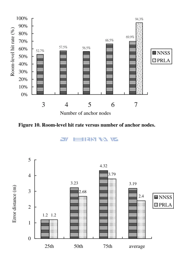
In Figure 10, although our proposed PRLA scheme used 7 anchor nodes, it can provide the room-level hit rate up to 94%. It is 24.4% better than the NNSS [1] when both scheme use
7 anchor nodes. Figure 11 shows the comparison of the 25th, 50th, 75th percentile values and
the average error distance. We found that when we applied our proposed PRLA scheme to the RADAR, the average error distance can be reduced from 3.19 m to 2.24 m. The reason why we can reduce the average error distance is that we have a good room-level hit rate to predict the room where the target is located, and the search space for the predict location is restricted to this room.
We also compare the proposed PRLA with another room-level localization scheme which is called Signpost algorithm in [12]. We want to know the difference of the delay time to enter a room and the room-level hit rate between the two algorithms through the following two scenarios.
Figure 12 shown the walking path of test environment 1, where we walk through Hallway1, Room3, enter Room4, exit Room4, exit Room3, finally go back to the Hallway1.
In Figure 13, we show the cumulative distribution function (CDF) of the delay time to enter Room4. We collected 50 experiment data. Experimental results show that Signpost can correctly detect the room with 96% accuracy and the delay time is less than 2 seconds. But the proposed PRLA scheme can correctly detect the room with 92% accuracy and the delay time is less than 3 seconds. This is because the proposed PRLA uses a circular queue to make the localization scheme more stable. Note that the bigger the queue size is, the more time we use to determine a room.
In Figure 14, we show the walking path of test environment 2, where we walk around Room2, Room3 and Room4,respectively, and in each room we stay for 5 minutes. At the same time, we run each localization algorithm to determine the room that the user is located. Figure 15 shows the room-level hit rate obtained in each room. We saw that the average room-level hit rate of our proposed PRLA scheme is 20% better than that of Signpost, when walking around Room2, Room3, and Room4. The high room-level hit rate of the proposed PRLA scheme is due to the path-restricted information. With this information, it can filter out unused signals sent by those anchor nodes located in not reachable rooms. According to the above two experimental results, the delay time to enter a room of the proposed PRLA was one second longer than that of Signpost; however the proposed PRLA was more reliable than Signpost because its average room-level hit rate is 20% better than Signpost, as shown in Figure 15.
1.2 3.23 4.32 3.19 1.2 2.68 3.79 2.4 0 1 2 3 4 5 25th 50th 75th average NNSS PRLA
Figure 11. Comparison of the 25th, 50th and 75th percentile values and the average error distance. 52.7% 57.5% 56.5% 66.5% 94.3% 69.9% 0% 10% 20% 30% 40% 50% 60% 70% 80% 90% 100%
3
4
5
6
7
NNSS PRLAFigure 10. Room-level hit rate versus number of anchor nodes.
Number of anchor nodes
Room-leve l hit r ate (%) Error distan ce (m) 20
Figure 12. Walking path of test environment 1.
Figure 14. Walking paths of test environment 2. 86% 67% 62% 72% 96% 87% 95% 92% 0% 10% 20% 30% 40% 50% 60% 70% 80% 90% 100%
Room2 Room3 Room4 average
Signpost PRLA ` Room-leve l hit r ate (%)
Figure 15. Room-level hit rate in test environment 2.
Chapter 5
Conclusions
5.1 Concluding remarks
We have presented an indoor localization system using a path-restricted room-level localization algorithm (PRLA) and a fingerprinting based technique in wireless sensor networks. Experimental results show that by applying our PRLA scheme to the RADAR system, it significantly improves the room-level hit rate from 69% to 94% and reduces the average error distance from 3.19 m to 2.24 m. In addition, the proposed PRLA scheme can be applied to any coordinate-based indoor location system to enhance its room-level hit rate and localization accuracy. We have also compared PRLA with Signpost which is also a room-based localization scheme. The results demonstrate that the delay time to enter a room of the proposed PRLA was one second longer than Signpost; however the proposed PRLA is more reliable than Signpost because its average room-level hit rate is 20% better than that of Signpost.
5.2 Future work
In the future we can apply the proposed PRLA to other coordinate-based localization algorithms, such as the Horus system [14] which uses a probabilistic fingerprinting technique to provide better localization accuracy. And we can also experiment to put more than one anchor node to an area (depends on area size), such as a room, to improve the room-level hit rate and thus localization accuracy.
Bibliography
[1] P. Bahl and V. N. Padmanabhan, ” RADAR: An in-building RF-based user tracking system,” in Proc. IEEE INFOCOM 2000, Vol.2, pp.775-784, 2000.
[2] P. Enge and P. Misra. “Special issue on gps: The global positioning system,” in Proc., 87(1):3-172, January 1999.
[3] A. Haeberlen, E. Flannery, A.M. Ladd, A Rubys, D.S. Wallach and L.E. Kavraki, “Practical Robust Localization over Large-Scale 802.11 Wireless Network,” The tenth ACM Int.Conf. MOBICOM2004, pp.70-84, Philadelphia, PA, USA, Sep. 2004.
[4] “Wireless Sensor Network Center,” [Online] Available: http://www.wsnc.ntu.edu.tw/ [5] L. Klingbeil and T. Wark, “A Wireless Sensor Network for Real-Time Indoor
Localisation and Motion Monitoring,” in Proc. Information Processing in Sensor Networks, pp.39-50, Apr. 2008.
[6] S. Wenming, H. Chuanhe, S. Mingkai, “ A Novel Positioning Algorithm in Wireless Sensor Networks Based on Indoor Connective Information,” in Proc. Sensors Applications Symposium, pp1-5, Feb. 2007.
[7] N. Noury, G. Virone, T. Creuzet, “The health integrated smart home information system (HIS2): rules based system for the localization of a human,” in Proc. Microtechnologies in Medicine & Biology 2nd Annual International, pp318-321, May, 2002.
[8] M .D'Souza, T. Wark, M.Ros, “Wireless localisation network for patient tracking, “ in Proc. Intelligent Sensors, Sensor Networks and Information Processing, pp.79-84, Dec. 2008.
[9] Asis Nasipuri and Kai Li, ”A Directionality Based Location Discovery Scheme for Wireless Sensor Networks,” in Proc. ACM international conference on Wireless sensor networks and applications, 2002, pp.105-111.
[10] A. Boukerche, H.A.B. Oliveira, E.F. Nakamura, A.A.F. Loureiro, “A Novel Location-Free Greedy Forward Algorithm for Wireless Sensor Networks,” in Proc. Communications, pp.2096-2101, May. 2008.
[11] P. Bahl and V. N. Padmanabhan, “Enhancements to the RADAR user location and tracking system,” Microsoft Corp., Tech. Rep. MSR-TR- 2000–12, Feb. 2000.
[12] K. D’HOE, G. Ottoy, P. Keersebilck, “Indoor room location estimation,” Development and application system, Suceava, Romania, 2008
[13] M. Youssef, A. Agrawala, and A. Udaya Shankar, “WLAN location determination via clustering and probability distributions,” IEEE Int. Conf. Pervasive Comput. Commun., Mar. 2003, pp. 143–151.
[14] M. Youssef and A. K. Agrawala, “Handling samples correlation in the Horus system,” IEEE INFOCOM 2004, Hong Kong, vol. 2, pp. 1023–1031, Mar. 2004.
[15] M. Lee and S. Lee, “Data Dissemination for Wireless Sensor Networks,” in Proc.Object
and Component-Oriented Real-Time Distributed Computing, pp.172-180, May. 2007. [16] M. Gao, F. Zhang, J. Tian, “Design and Implementation of Wireless Sensor Network
Data Collection Terminal Based on ARM9,” in Proc. Computing, Communication, Control, and Management, pp.587-590, Aug. 2008.
[17] M. Brunato and R. Battiti, “Statistical learning theory for location fingerprinting in wireless LANs,” Comput. Netw., vol. 47, pp. 825–845, 2005.
[18] R. Battiti, T. L. Nhat, andA.Villani, “Location-aware computing:Aneural network model for determining location in wireless LANs,” Tech. Rep. DIT-02–0083, 2002.
[19] S.H. Chaudhary, A.K. Bashir, “[ETCTR] Efficient Target Localization by Controlling
the Transmission Range in Wireless Sensor Networks,” in Proc.Networked Computing
and Advanced Information Management, vol. 1, pp.3-7, Sept. 2008.
[20] V. Otsason, A. Varshavsky, A. LaMarca, and E. de Lara, “Accurate GSM indoor localization,” UbiComp 2005, Lecture Notes Computer Science, Springer-Varlag, vol.
26 3660, pp. 141–158, 2005.
[21] “Moteiv,” [Online] Available: http://www.moteiv.com.
[22] J. Hightower and G. Borriello. Particle filters for location estimation in ubiquitous computing: A case study. In N. Davies, E. Mynatt, and I. Siio, editors, in Proc. Sixth International Conference on Ubiquitous Computing, volume 3205, pages 88–106. Springer-Verlag, September 2004.
[23] V. Otsason, A. Varshavsky, A. LaMarca, and E. de Lara, “Accurate GSM indoor localization,” UbiComp 2005, Lecture Notes Computer Science, Springer-Varlag, vol. 3660, pp. 141–158, 2005.
[24] H. Liu, H. Darabi, P. Banerjee and J. Liu, ” Survey of Wireless Indoor Positioning Techniques and Systems,” IEEE Trans. Syst., Man, Cybern. C, Appl. Rev, vol.37, pp.1067-1080, Nov. 2007.
[25] “An indoor localization system for integrated wireless local area networks and sensor
networks (in Chinese),” [Online] Available: http://acnlab.csie.ncu.edu.tw/wasn06/CR2/p59.pdf

![Figure 9. Octopus II sensor node [4].](https://thumb-ap.123doks.com/thumbv2/9libinfo/8595307.189925/28.892.132.748.111.1077/figure-octopus-ii-sensor-node.webp)