Terephthalate)/Liquid Crystalline Polymer Blends by Solid
Epoxy Resin as a Coupling Agent
HUNG-CHIH CHIN, KUO-CHAN CHIOU, and FENC-CHIH CHANG*
Institute of Applied Chemistry, National Chiao-Tung University, Hsin-Chu, Taiwan, Republic of China
SYNOPSIS
A selected reactive coupling agent can be served as an effective compatibilizer for certain immiscible and incompatible blends should both blend constituents possess the necessary functional groups that can react with the coupling agent at comparable rates. Solid epoxy resin with two epoxide endgroups per molecule was demonstrated to be an efficient reactive compatibilizer for the incompatible blends of poly(ethy1ene terephthalate) (PET) and co- polyester liquid crystalline polymer (LCP) by functioning as a coupling agent. The main chain structure of the epoxy resin is neither identical nor miscible with PET and LCP and tends to reside at interface during melt mixing. This preferential residence gives the epoxy compatibilizer greater opportunity to react with both PET and LCP simultaneously to produce the in situ-formed epoxy-b-PET-b-LCP mixed copolymer. This in situ-formed mixed copolymer is highly effective in compatibilizing the PET/LCP blends. This reactive epoxy compatibilizer enhances the LCP fibril formation and results in substantial improvements on stiffness and toughness of the PET/LCP blends. 0 1996 John Wiley &
Sons, Inc.
INTRODUCTION
When blended with isotropic thermoplastics (TPs), the semirigid thermotropic liquid crystalline poly- mers (LCPs) tend t o orient parallel t o the flow di- rection to the fibrilar L C P morphology as in situ- formed reinforced composites. Since the pioneer work of Wilkes and Colleagues'-3 on the polymer blends containing LCP in the early 1980s, this area of technology has attracted tremendous attention during last decade with hundreds of articles ap- pearing in open literature and patents. A key t o achieve the desirable reinforcement of the TP ma- trices with LCPs is the creation of L C P fibrils by use of appropriate processing conditions. This ap- proach has been widely applied to various TP blend systems and was described in a few recent
review^.^.^
Except for a few cases, most T P / L C P blends are considered t o be immiscible and incompatible with* To whom correspondence should be addressed.
Journal of Applied Polymer Science, Vol. 60, 2503-2516 (1996)
0 1996 John Wiley & Sons, Inc. CCC 0021-8995/96/132503-14
poor interfacial adhesion. Poor interfacial adhesion of the T P / L C P blends is partially responsible for the lower mechanical properties usually observed when comparing with the theoretically predicted values. At first look, the solution seems t o be ob- viously simple by compatibilizing the T P / L C P blends, a common approach similar to most com- patibilized TP/TP blends. Compatibilization of TP/ TP blends by either reactive or nonreactive com- patibilizers has a much longer history and is rela- tively well understood a s described in several recent A well-compatibilized TP/TP blend is characterized with finer phase domains, lower in- terfacial tension in the melt state, increased inter- facial adhesion in the solid state, higher morpho- logical stability against coalescence, and improved mechanical properties. However, most compatibil- ized T P / L C P blends have the tendency t o reduce the number and length of the resulted LCP fibrils or even convert the LCP fibrils into droplet do- Therefore, a typically compatibilized TP/
L C P blend relative t o the uncompatibilized coun- terpart, the gain achieved by the adhesion increase 2503
may or may not be able to offset the loss due the reduction of the reinforced LCP fibrils. This is probably the reason why the observed mechanical properties of the compatibilization of TP/LCP blends varied with systems and conditions. This is probably also the reason why the compatibilization of TP/LCP blends has not received the same atten- tion as the TP/TP blends.
Compatibilization of the TP/LCP blends have rarely been reported until very recently. The inter- changed product between the blend constituents (one is LCP) were probably the first approach to compatibilize the TP/LCP blends. Amendola et al.13 used the ester interchanged products of polycarbon- ate (PC) and copolyester LCP to compatibilize the PC/LCP blends. Most interchanged products as compatibilizers for their respective components usually result in inferior toughness and reduced crystallinity (if the TP is a crystalline polymer), which were described in details in our recent
re vie^.^
Compatibilized blends of polypropylene (PP) with various L C P S " J ~ * ' ~ - ' ~ made up of more than half of all the reported compatibilized TP/LCP blends until present. The PP/LCP blends compatibilized with
PP functionalized by maleic anhydride14-17 and acrylic acid" resulted in higher strength and stiff- ness (tensile strength and modulus) but lower toughness (tensile elongation and impact strength). On the other hand, the PP/LCP blends compati- bilized with epoxy-containing copolymers1'~'2 or an ethylene-based reactive t e r p ~ l y m e r ' ~ resulted in toughness improvement but suffered the loss of strength and stiffness. Polymer blends between LCP with polystyrene (PS) and Noryl [alloy of PS and poly(pheny1ene oxide) (PPO)] compatibilized by styrene-glycidyl methacrylate copolymer (SG) re- sulted in both toughness and stiffness improvements simultaneously.'0~19 Essentially, all abovementioned compatibilized TP/LCP blends utilized the reactive type compatibilizers or at least tried. Kobayashi et al. recently reported the use of nonreactive copoly- mer, a thermotropic liquid crystalline block-graft copolymer composed of thermotropic polycarbonate (LCPC) in the backbone, and PS segment in the side chain to compatibilize the incompatible blends between LCPC with PS (A/A-B/B type)" and with PPO (A/A-C/B type, where C and B are miscible).'l Poly(ethy1ene terephthalate) (PET)/LCP blends using various types of copolyester LCPs have been one of the most intensively investigated TP/LCP blend system. In fact, the earliest reported TP/LCP blends used P E T as the matrix in the The miscibility or compatibility of the various PET/LCP blends vary depending on the LCP structure. Amano
and NakagawaZ2 studied the drawing behavior of the PET/LCP blends and reported that the orientation of the LCP was induced as well as that of the P E T during drawing. Brostow et al.23 investigated the thermophysical, rheological, and mechanical prop- erties of the PET/LCP blends and developed an is- land model to explain the results. Zhuang et al.24 showed substantial viscosity reduction and me- chanical property improvement of the PET/LCP blends. KO et al.25 also investigated the structure- properties behavior of the extruder cast film of the PET/LCP blends. Shin and Chung26 studied the in- terfacial adhesion and the mechanical properties of
the PET/LCP blends and found that the interfacial adhesion was much improved by the introduction of
a long flexible spacer in the LCP main chain. Sil- verstein et al.27 studied the core and skin gradient structure of the injection molded blends of PET/ LCP and showed the highest orientation in the flow direction a t the mold surface and the lowest a t core region. Perkins et a1.'* studied the effect of temper- ature, composition, and shear rate on the viscosity and morphology of the PET/LCP blends. Mithal et al.29 studied the in situ composite fibers of the PET/ LCP blends and found almost additive behavior with regard to tensile modulus and strength but resulted in a radical decline in tensile elongation. Kyotani et al.30 reported the tensile modulus increases linearly with the increase of the LCP content for the blend containing
>lo%
LCP but hardly contributed to the improvement of the tensile properties for <5% LCP. Seppala et al.31 reported partial miscibility between P E T and LCP and the presence of LCP serves as a nucleating agent to accelerate the P E T crystalli- zation. Heino and Seppala3' reported that a t high shear rate, the viscosity ratio of LCP/PET between 0.5 and 1.0 led to good fiber formation. Kim and Denn33 reported some interactions betweenPET
and LCP based on the observed melting and crystalli- zation depression of the blends. Mehta and D e ~ p u r a ~ ~ also investigated the PET/LCP fibers and reported significant improvement in modulus and strength. Narayan-Sarathy et al.35 blended P E T with a novel LCP with a flexible side group and re- sulted in 80% reduction on the apparent viscosity for only 2-5% LCP presence in the blends.Including the above mentioned literature, the ap- plication by adding a third component compatibil- izer, reactive or nonreactive type, into an incom- patible PET/LCP blend has not yet been found by the authors a t present. We discovered that many epoxy-containing compounds or polymers are ex- cellent in compatibilizing the polyester/polyester, polye~ter/polyamide,~~ p ~ l y e s t e r / P P O , ~ ~ and poly-
amide/PP03' blends. The basic criterion for such an approach to be applicable is that both blend con- stituents must possess certain necessary functional groups that can react with the epoxy under melt conditions to form various copolymers containing segments of both blend components. The blends containing copolyester LCP with many thermo- plastic polyesters are classified in the polyester/ polyester blend system.
This paper reports the resultant structure-prop- erties of the PET/LCP blends compatibilized by a solid-state bisphenol-A epoxy resin (MW 5000).
EXPERIMENTAL
The P E T with IV-1.0 was obtained from the Shin- kong Synthetic Fibers Corp. of Taiwan. The copo- lyester LCP, Vectra A900, was donated by the Hoechst Celanese Corp. The reactive compatibilizer, a bisphenol-A solid epoxy resin NPES-707 with MW 5000, was donated by the Nan Ya Plastics Corp. of Taiwan. The catalyst ethyl triphenylphosphonium bromide was purchased from Merck.
Melt blending was carried out on a 30-mm cor- otating twin-screw extruder. The extruded pellets were dried in an oven a t 100°C for at least 10 h and injection molded into standard ASTM testing spec- imens using an Arburg 3-oz injection-molding ma- chine. The detailed processing conditions for the extrusion and injection molding are listed in Table
I. The torque versus time relation was obtained in a Torque Rheometer, system 90, from Hakke Co. a t 285°C and under constant rotating speed of 30 rpm. Melt flow rates of the blends were carried out ac- cording to ASTM-D1238 a t 285°C using a 2.16-kg load on an Automatic Flow Rate Timer, Model 3A of Ray-Ran Co. The capillary rheological measure- ments were carried out by following the ASTM-
Table I Processing Conditions
D3835 method at 285°C by using a rheometer from Kayeness Company.
Thermal properties were studied by the differ- ential scanning calorimetry (DSC) from -25 to 300°C at a heating rate of 15"C/min on a DSC an- alyzer from Seiko Co. of Japan. The percent of PET
crystallinity in the blends was determined by the following equation:
Where X c is the percent crystallinity of the blend, AH, is the measured heat of fusion of the P E T com- ponent of the blend, AHpE* is the theoretical heat of fusion of the 100% crystallinity of the pure PET,
and x is the mass fraction of the P E T in the blends. The morphologies of the cryogenically fractured surfaces of the injection-molded specimens were ex- amined a t core and skin regions perpendicular and parallel to the injection flow direction. The LCP
fi-
brilar morphologies were also inspected by a hot- stage microscope by heating the sample a t 275°C to melt the P E T matrix while retaining the original LCP morphology.Notched and unnotched Izod impact strengths were measured a t ambient conditions according to ASTM-D256 methods. Standard tensile tests were also carried out a t ambient conditions by following the ASTM-D638 method using a cross-head speed of 5 mm/min.
RESULTS AND DISCUSSION
Fundamentals on Reactive Compatibilization
A conventional C-X reactive compatibilizer in a bi- nary A / B blend system has the nonreactive C seg- ment structurally identical or miscible with com-
~~
Extrusion blending
Stage: 1 2 3 4 5 6 7 8 9 Die
Temp. ("C) 180 270 275 280 285 285 280 280 280 285 Motor rate: 250 rpm
Feeder rate: 300 g/min Injection molding Zone 1 Temp. ("C) 260 Screw rate: 200 rpm Mold temperature: 80°C Cycle time: 20 s 2 285 3 285 Nozzle 280
ponent A and the reactive
X
groups that are capable of a chemical reaction with component B of the blend to form in situ the C-X-B graft or block co- polymer during melt processing. By blending A, B,and C-X simultaneously, because the reactive C-X compatibilizer is inherently more miscible or more compatible with the component A, C-X is preferably
to reside evenly in the A phase before the occurrence of the anticipated reaction. Therefore, the reaction between C-X and component B should take place
at the interface and the in situ-formed C-X-B co- polymer tends to anchor along the interface to re- duce the interfacial tension in the melt state. Not all added C-X compatibilizer in the blend has the chance to make contact and react with B component during a typical melt-mixing process and a portion of them may have the chance to react more than once. The extent of such in situ reactions depends on reactivity, blending sequence, presence of a suit- able catalyst, processing conditions, and the X con- tent in the C-X compatibilizer. C-X itself is not considered as a compatibilizer for the A / B blend; only the in situ-formed C-X-B copolymer is able to function as a compatibilizer of the blend. Such a reactive compatibilization approach is not univer- sally applicable to all polymer pairs. Reactive com- patibilization approach is potentially valid only for those blend pairs with a t least one blend component possessing certain necessary functional groups ( as chain ends or within main chain) that can be reacted with the reactive compatibilizer. In general, a blend component possessing chain-end functional groups
is particularly suitable for such in situ reactive com- patibilization. Typical examples are - COOH (and/or -OH) of polyester, - NHp of polyamide,
and phenolic -OH of PPO. The functional groups X in C-X compatibilizer copolymer can also be as chain-ends or evenly distributed within the main chain to produce in situ the block or graft copolymer.
For a graft type reaction by preblending the C-X compatibilizer with B component in a sequential blend process, excessive reaction tends to take place and produces the highly branched comb-like graft copolymer or even a crosslinked network, which is certainly undesirable. Usually, a lightly grafted co- polymer, one or a few grafts per main chain, is more efficient than the heavily grafted Therefore, it is essential to properly control the extent of the graft reaction by optimizing the reactive group con- centration, blending sequence, catalyst, and pro- cessing conditions to achieve the best performance of the resultant
blend^.^
If both blend components (A and B ) contain the functional groups that can react with the reactive
compatibilizer with comparable rate, a fraction of
the in situ-formed copolymers may include both A
and B components. Evidence indicated that the for- mation of the mixed copolymer is advantageous and resulted in further improvement of the compatibil- ized blend.” The compatibilized Noryl/ LCP blend improved more in morphological and mechanical properties than the corresponding compatibilized
PS
/
LCP blend above their respective uncompati- bilized blends. In the NoryllLCP blend system, the reactive compatibilizer, SG, is able to react with both LCP and PPO (in Noryl) with comparable reactiv- ity, and a certain amount of the mixed graft copol- ymer (SG-g-LCP-g-PPO) is expected to be formed.” In the P S / L C P system, PS is a nonreac- tive component, and only the SG-g-LCP graft co- polymer is expected to be formed.” The mixed co- polymer is expected to be more effective as a com- patibilizer of the blend, which is probably responsible for the difference observed between these two blend systems.If the in situ-formed mixed copolymer is indeed more effective in compatibilizing a blend where both blend components possessing the necessary func- tional groups, then the presence of the C segment and its miscibility with component A required for a conventional reactive C-X compatibilizer may not be critical or even undesirable. That means a com- pound C-X, a small molecule, an oligomer, or a polymer containing multiple X functional groups should also act as a reactive compatibilizer for the A/B blend, disregarding the miscibility between the C segment in C-X and one of the blend constituents. In that sense, C-X simply functions as a coupling agent to produce the mixed copolymer containing both A and B components. Realistically, lower com- patibility between C segment with blend constitu- ents A and B is actually desirable because the C-X coupling agent would prefer to reside a t interface and has a better opportunity to contact and react with both A and B components simultaneously. Therefore, blends between copolyester LCP with many thermoplastic polyesters are expected to be compatibilized by any epoxy compound with mul- tiple epoxy functional groups. Both copolyester LCPs and thermoplastic polyesters possess simi- lar - COOH and -OH endgroups, and their reac-
tivities with epoxy are also expected to be compa- rable. Therefore, a fraction of the in situ-formed products should be in the form of mixed copolymer. Several blend systems including the LCP component have been demonstrated by us that such a coupling agent approach is highly efficient when both blend components contain the necessary functional
Table I1 Extruder Current and Die Swelling Ratio Extruder Current Composition (Amp) PET 23.5 PET/LCP/Epoxy 90/10/0.5 21.5 PET/LCP/Epoxy 90/10/1 21.6 PET/LCP 90/10 21.2 PET/LCP/Epoxy 90/10/2 21.2 PET/LCP/Epoxy/Cat 90/10/2/0.02 22.1 Die Swelling Ratio 1.35 1.38 1.35 1.35 1.31 1.31 ~ ~~
Extruder temperature range; 270-285°C; screw rotation rate; 250 rpm; feeding rate, 60 g/min. groups. The main segment structure of the coupling
agent used in this study (solid epoxy resin) is neither identical nor miscible with the blend components LCP and PET. This intermediate molecular weight epoxy resin with two epoxy endgroups simply func- tions as a coupling agent unlike most other conven- tional reactive compatibilizers. A low-molecular- weight multiple functional epoxy compound was demonstrated to be even a better reactive compa- t i b i l i ~ e r , ~ ~ resulting in drastic improvements in me- chanical properties. As mentioned earlier, this un- conventional reactive compatibilization through in
situ coupling reaction can be applied to many blend systems as long as both blend constituents contain- ing the needed functional groups that can react with the reactive coupling agent with comparable reac- tivity. If one of the blend component is innert, it can be prefunctionalized with certain reactive groups, partially or fully, and the same coupling ap- proach is still valid. Polypropylene is a nonreactive component in the blends of PP/polyamide and PP/
PBT. By functionalizing a small fraction of the PP
with maleic anhydride (MPP), the ethylene-glycidyl methacrylate (EGMA) became a effective reactive compatibilizer for the blends of PP/polyamide4' and PP/poly(butylene terephthalate ( PBT)43 by func- tioning as a coupling agent to form the EGMA-g- PP-g-PA and EGMA-g-PP-g-PBT mixed copoly- mers, respectively.
swelling ratios based on the PET/LCP = 90/10 blend series. The extruder currents of the blends, with and without compatibilizer, are less than the pure PET. Addition of small amount of LCP im- proves the TP matrix processibility by lowering its shear viscosity which has been well reported.24,2s,32,35 The increase of the extruder current due the ex- pected molecular weight increment by the reactive compatibilizer is not very significant. The observed die swelling problem of the uncompatibilized blends has been reduced after compatibilization.
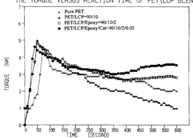
Torque Versus Time
Figure 1 illustrates the torque versus time curves for P E T and the uncompatibilized and compatibil- ized PET/LCP 90/10 blends. Pure P E T and the un- compatibilized blend show torque decline continu- ously with time, an indication of thermal degrada- tion. The compatibilized blend maintains its torque fairly steady up to 600 min. The compatibilized blend containing 200 ppm catalyst results in slight in- creases of the resultant torque value. Obviously,
THE TORQUE VERSUS REACTION TIME OF PET\LCP BLEND
1 ., PurePET A PETLCP=90/10 o PET/LCP/Epoxy=PO/IO/2 m PETLCPIEpoxy/Cat=90/lO/2lO 02 6 - Processi bi lity
Processing of this PET/LCP blend system at lower LCP content is rather smooth even without the presence of the compatibilizer. At higher LCP con- tent (15%), processing problems such as die swelling
or melt fracture occasionally occurred. In generally, the presence of the compatibilizer did improve the extrusion processibility and resulted in smoother extrusion. Table
I1
shows the summarized results of the required extruder power outputs and the die04 0 40 100 150 200 2 0 300 350 4 0 0 450 d00 E!50 $00 TIME kXCdND)
'
I I l l Figure 1ious PET/LCP 90/10 blends.
IE 4-
thermal stability improvement is an additional ad- vantage by using the reactive compatibilizer.
n PET 0 PL-90 0 PL-9C-92 PL-9C-92-C
Melt Flow Rates (MFRs)
Table I11 gives the MFR data of all the blends in- vestigated. Without the presence of the compatibil- izer, the PET/LCP blends result in higher MFR as would be expected. The MFR decreases from all three blend series with the increase of the quantity of the compatibilizer and the presence of the cata- lyst. Molecular weight increase from the anticipated reactions between the epoxy with P E T and LCP is believed to be responsible for the observed lower MFR from the compatibilized blends. The interfacial friction caused by the in situ-formed copolymer an- choring along the interface may also partially con- tribute to the shear viscosity increase.
Capillary Rheornetry
Figure 2 shows the apparent viscosity versus shear rate curves for pure P E T and uncompatibilized and compatibilized PET/LCP 90/10 blends. Substantial reduction on the P E T viscosity after blending with
10% LCP has been observed. The addition of 2 phr of the epoxy compatibilizer does not cause any vis- cosity increase, and it actually decreases the viscos- ity slightly. However, the compatibilized blend con- taining 200 ppm catalyst results in substantial vis- cosity rise but still lower than that of the pure PET.
Table I11 MFR of the PET/LCP Blends
Composition MFR (g/min) P E T PET/LCP 95/5 PET/LCP/Epoxy 95/5/0.5 PET/LCP/Epoxy 95/5/1 PET/LCP/Epoxy 95/5/2 PET/LCP/Epoxy/Cat 95/5/2/0.02 PET/LCP 90/10 PET/LCP/Epoxy 90/10/0.5 PET/LCP/Epoxy 90/10/1 PET/LCP/Epoxy 90/10/2 PET/LCP/Epoxy/Cat 90/10/2/0.02 PET/LCP 85/15 PET/LCP/Epoxy 85/15/0.5 PET/LCP/Epoxy 85/15/1 PET/LCP/Epoxy 85/15/2 PET/LCP/Epoxy/Cat 85/15/2/0.02 40.6 42.2 38.5 30.3 27.5 25.5 44.2 33.5 27.2 20.0 18.0 45.3 33.1 30.5 20.3 18.6 Load, 2.16 kg; Temperature, 285°C. It 2 ii 3 Apparent Shear R a t e ( l / s e c ) Figure 2
for P E T and various PET/LCP 90/10 blends.
Apparent viscosity versus shear rate curves
DSC Analyses
Thermal properties analyzed by DSC for pure P E T and various blends are summarized in Table IV. The Tgs and T,s of the P E T component in the blends are only slightly higher than the pure P E T but are not very substantial. The P E T crystallinity in- creases by blending with a small amount of LCP, which has been well-recognized. The presence of LCP can serve as a crystallization nucleation agent to promote P E T crystallization. The presence of the epoxy compatibilizer further increases the P E T crystallinity for the blends containing 5 and 10% of LCP. The epoxy compatibilizer results in finer LCP domains, which should provide greater surface con- tacting area between phases to induce higher P E T crystallinity. However, in the PET/LCP 85/15 blends, the compatibilized blends show slight de- crease of the P E T crystallinity. The addition of 200 ppm catalyst in the compatibilized blends results in substantial reduction of the P E T crystallinity. The compatibilized blends containing catalyst indeed cause further reduction of the LCP domain size but result in lower PET crystallinity unexpectedly. Greater mutual solubility by the better compatibil- ized blends (with catalyst) may have higher contents of LCP and the mixed copolymer dissolving in the P E T phase, hindering the P E T crystallization.
Scanning Electron Microscopy (SEM) Morphologies
Figure 3 illustrates the schematic diagram showing the four locations of an injection molded specimen, from the planes parallel and perpendicular to flow direction a t core and near skin regions, that have
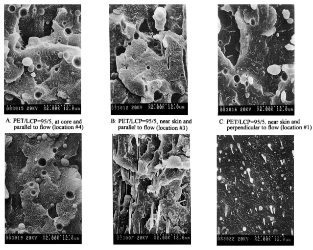
been examined by SEM. Because the LCP spherical dimension is a t the core region, the morphologies viewing from both directions (locations 2 and 4 in Fig. 3) are essentially the same. Therefore, only the morphologies parallel to the flow (location 4) are presented here. Figure 4(A)-(C) shows the SEM micrographs of the uncompatibilized PET/LCP 95/ 5 blend taken from three locations: 1, 3, and 4. No
LCP fibril can be detected from this blend with low LCP content. LCP in the blend has to exceed a crit- ical level to form the fibril morphology depending on processing conditions. Figure 4(D) and
(F)
gives the micrographs of the PET/LCP/Epoxy 95/5/1 compatibilized blend taken at the same three loca- tions. At the core region [Fig. 4(D)], the sizes of the LCP spherical particles are comparable with that of the corresponding uncompatibilized blend [Fig. 4(A)]. Figure 4(E) is the micrograph parallel to flow near skin region (location 3) that clearly shows the formation of the long LCP fibrils. Figure 4(F) shows the micrograph perpendicular to the flow (location 4) where great numbers of the small circular LCP domains are present. By comparing Figure 4(E) and (F) for the same spot but viewed by two different angles, these circular LCP domains can be confirmed as the fractured fibrils rather than as the droplet LCP particles. The results observed from Figure 4 reveal that the presence of 1 phr epoxy reduces the LCP domain size and induces greater fibril forma- tion near skin region but is relatively unaffected at core region. Figure 5(A)-(C) shows the morphologies of the uncompatibilized PET/LCP 90/10 blend viewing from the same three locations. Coarse LCPInjection molded specimen
Figure 3
locations where SEM micrographs were taken.
Schematic diagram shows the directions and
fibrils now can be found near the skin region [Fig. 5(B) and (C)] whereas the LCP phase still remains as droplet domains at the core region [Fig. 5(A)]. Figure 5(C) shows the pullout fibrils from the frac- ture surface near the skin region of the uncompa- tibilized blend, an indication of poor interfacial adhesion. Figure 5(D)-(F) gives the morphologies of the compatibilized PET/LCP/Epoxy 90/10/1 blend. At the core region [Fig. 5(D), location 41, the LCP spherical particles are relatively smaller than those of the uncompatibilized blend [Fig. 5(A)]. Near the skin region [Fig. 5(E), location 31, the LCP fibrils become finer with significantly higher aspect ratio relative to the uncompatibilized blend [Fig. 5(B)]. Figure 5(F) shows the fractured LCP fibrils without any single pullout fibril being found. Improved in- terfacial adhesion results in fibril fracture instead of fibril pullout during sample cryogenical fracture.
Table IV Thermal Properties of the PET/LCP Blends
AHPET % PET T g Tm Composition
(Jk)
Crystallinity ("C) ("C) PET 26.4 22.6 80.1 248.1 PET/LCP 95/5 28.4 25.6 82.8 250.6 PET/LCP/Epoxy 95/5/0.5 29.6 26.7 81.2 250.6 PET/LCP/Epoxy 95/5/1 32.6 29.7 82.1 250.7 PET/LCP/Epoxy 95/5/2 28.2 26.0 82.2 250.6 PET/LCP/Epoxy/Cat 95/5/2/0.02 20.4 18.8 83.6 248.9 PET/LCP 90/10 30.2 28.8 80.7 248.7 PET/LCP/Epoxy 90/10/0.5 31.1 29.8 81.0 250.0 PET/LCP/Epoxy 90/10/1 30.0 28.9 80.8 250.0 PET/LCP/Epoxy 90/10/2 32.0 31.9 81.1 249.5 PET/LCP/Epoxy/Cat 90/10/2/0.02 26.6 25.8 82.8 249.8 PET/LCP 85/15 26.0 26.2 82.8 250.0 PET/LCP/Epoxy 85/15/0.5 24.4 24.7 82.6 250.6 PET/LCP/Epoxy 85/15/1 25.4 25.9 81.8 251.2 PET/LCP/Epoxy 85/15/2 25.0 25.7 82.0 251.3 PET/LCP/Epoxy/Cat 85/15/2/0.02 24.2 24.9 82.2 25 1.6A: PETLCP=95/5, at core and parallel to flow (location #I)
B: PET/LCP=95/5, near skin and
parallel to flow (location #3) C: PET/LCP=95/5. near skin and perpendicular to flow (location #1)
D: PET/LCP/Epoxy=95/5/1 (location
Figure 4 SEM micrographs of the uncompatibilized and compatibilized PET/LCP 95/ 5 blends. (A) PET/LCP 95/5, a t core and parallel to flow (location 4); (B) PET/LCP 95/ 5, near skin and parallel to flow (location 3); (C) PET/LCP 95/5, near skin and perpendicular to flow (location 1); (D) PET/LCP/Epoxy 95/5/1 (location 4); (E) PET/LCP/Epoxy 95/ 5/1 (location 3); (F) PET/LCP/Epoxy 95/5/1 (location I).
E: PET/LCP/Epoxy=95/5/1 (location #3) F: PETLCPiEpoxy=95/5/1 (location #1)
Again, the results observed from Figure 5 demon- strate that the compatibilization of the PET/LCP blend breaks down the originally coarse fibrils into greater numbers of the finer LCP fibrils. Addition- ally, the adhesion between fibrils and the P E T ma- trix has been enhanced.
Effect of Shear Rate on Fibril Formation by Hot- Stage Microscope
The original dimension of the LCP component in the blend can be easily examined by the hot-stage optical microscope at a temperature above the T,,, of the P E T but still below the T,,, of the LCP. The strings from the capillary rheometrical measure- ments by varying the shear rates were used to study the effect of shear rate on the LCP fibrilar structure. Three different shear rates, y = 1 X
lo2
s-l, 8 Xlo2
s-l, and 2 X
lo3
s-l were adopted in this investiga- tion. Figure 6 shows the hot-stage micrographs of the uncompatibilized PET/LCP 90/10 blend at dif- ferent shear rates where the LCP domains are ir-regular nonfibrillar structure, regardless of shear rate. For the blend containing lower epoxy content, PET/LCP/Epoxy 90/10/0.5, the LCP fibrilar struc- ture begins to be formed at the intermediate shear rate [Fig. 7(B), y = 8 X 10² s-'I. At high shear rates (y = 2 X
lo3
s-l), the well-established long LCP fibrils can be clearly observed in the blend [Fig. 7(C)]. Figure 8 shows the micrographs of the com- patibilized blend containing higher epoxy content( 2 phr). A t low shear rate (y = 1 X 10' s-'), the LCP phase of this compatibilized blend is still existed as a droplet morphology [Fig. 8(A)]. At higher shear rates, the LCP fibrils are produced [Fig. 8(B) and (C)]. For the compatibilized blend containing the
A: PET/LCP=90/10 (location M), B: PETILCP=90/10 (location #3) C: PET/LCP=90/10 (location #l),
D: PET/LCP/Epoxy=90/10/1 (location #4) E: PEWLCP/Epoxy=90/10/1 (location #3) F: PET/LCPQO@O/~O/~ (location #1) Figure 5 SEM micrographs of the uncompatibilized and compatibilized PET/LCP 90/
10 blends. (A) PET/LCP 90/10 (location 4); (B) PET/LCP 90/10 (location 3); (C) P E T / LCP 90/10 (location 1); (D) PET/LCP/Epoxy 90/10/1 (location 4); (E) PET/LCP/Epoxy 90/10/1 (location 3); (F) PET/LCP/Epoxy 90/10/1 (location 1).
Figure 6
rates. ( A ) y = 1 X lo's-'; (B) y = 8 X
lo2
s-'; (C) y = 2 Xlo3
s-'.(a) (b)
(4
Figure 7
shear rates. (A) y = 1 X lo's-'; (B) y = 8 X lo's-'; (C) y = 2 X
lo3
s-'.Hot-stage micrographs of the PET/LCP/Epoxy 90/10/0.5 blend under different
additional 200 ppm, catalyst results in much finer fibrils at high shear rate [Fig. 9(C)]. A critical shear rate is required to form the LCP fibrils and has been widely reported. However, it is still a controversial issue whether the compatibilization will enhance, reduce, or even inhibit the LCP fibril formation. Based on the limited literature reported in the area of compatibilization of TP/LCP blends, most sys-
tems tend to reduce or inhibit the LCP fibril for-
LCP blend systems known by the authors that the fibril formation is enhanced by compatibilization. Therefore, we believe that the effect of compatibil- ization on fibril formation depends on blend system and the processing conditions. More studies on ad- ditional compatibilized TP/LCP blend systems must be carried out to tell what factors are important to enhance the fibril formation.
mation after compatibilization including two of our
previous papers on PS/LCP'' and PP/LCP'' blends. Mechanical Properties In addition to the present study, the Noryl/LCP
blendsIg and other PET/LCP blends compatibilized by a small MW epoxy resin4' are the only three TP/
The summarized tensile properties and unnotched impact strengths are listed in Table V and Figures 10 and 11. The PET/LCP 90/10 blend series shows
(a) (b)
(4
Figure 8
shear rates. (A) y = 1 X lo's-'; (B) y = 8 X lo's-'; (C) y = 2 X
lo3
s-'.(4
(b) (c) Figure 9different shear rates. (A) y = 1 X lo's-*; (B) y = 8 X
lo2
s-'; (C) y = 2 Xlo3
s-'. Hot-stage micrographs of the PET/LCP/Epoxy/Cat 90/10/2/0.02 blend undera definite trend of property improvement according to the extent of compatibilization, whereas the trend in other series is somewhat less consistent. If we consider the tensile strength and modulus as the material stiffness, then the tensile elongation to break and impact strength is the material toughness. Figure 10 shows the stiffness (tensile modulus and strength) improvement with the increase of the epoxy compatibilizer quantity and the presence of catalyst. Figure 11 shows similar trend for the toughness (tensile elongation and impact strength) enhancement. Overall, both stiffness and toughness are enhanced through compatibilization for this PET/LCP blend system. With only a few excep-
t i o n ~ , ' ~ ~ ~ ~ essentially all previously reported com- patibilized TP/LCP systems result in either stiffness improvement (but lower on toughness) or toughness enhancement (but lower on stiffness) relative to the uncompatibilized counterparts. Two major factors are important in dictating the mechanical properties of the resultant TP/LCP blends: the formation of the fibrilar LCP structure and the increase of the interfacial adhesion. Compatibilization of any poly- mer blend will increase the interfacial adhesion without any doubt by all. As mentioned above, com- patibilization of a TP/LCP blend may enhance, re- duce, or even inhibit the LCP fibril formation de- pending on systems and processing conditions. In
Table V Tensile and Impact Properties of the PET/LCP Blends
Tensile Modulus Tensile Strength Tensile Elongation Unnotched Impact
Composition (MPa) (MPa)
( % I
(J/m)PET/LCP 95/5 PET/LCP/Epoxy 95/5/0.5 PET/LCP/Epoxy 95/5/1 PET/LCP/Epoxy 95/5/2 PET/LCP/Epoxy/Cat 95/5/2/0.02 PET/LCP 90/10 PET/LCP/Epoxy 90/10/0.5 PET/LCP/Epoxy 90/10/1 PET/LCP/Epoxy 90/10/2 PET/LCP/Epoxy/Cat 90/10/2/0.02 PET/LCP 85/15 PET/LCP/Epoxy 85/15/0.5 PET/LCP/Epoxy 85/15/1 PET/LCP/Epoxy 85/15/2 2630 2361 2601 2782 2952 2868 2954 3437 3452 3589 3891 3979 3698 4200 24.7 25.3 27.1 28.2 40.1 44.9 49.7 50.9 53.6 60.7 67.7 71.6 79.0 70.8 7 > 100 > 100 > 100 > 100 5 7 10 1 2 15 3 5 6 10 766 802 735 778 810 386 432 562 616 620 322 383 444 520
4000 3500 3000 n 2500 Y)
-
g
2000 Ea
1500 0-
.- c” 1000 500 0 ~~ ~PET PETILCP PETILCPIEpon PETILCPIEpon PETlLCPIEpom PETlLCPIEporylCat
=9011ll =90110105 =w1011011 =wmn =poiion10 02 Composition 70 60 50 4
P.
a
40 * 30 f2
20 10 0 Figure 10 strength.Effect of epoxy compatibilizer and catalyst on tensile modulus and tensile
addition to the expected interfacial adhesion in- crease, the enhanced LCP fibril formation in this compatibilized PET/LCP blends is responsible for the improvements on both stiffness and toughness.
levels after compatibilizing by the SG reactive com- patibilizer. The compatibilized Noryl/LCP blends give much more improvements than that for the PS/ LCP blends reflecting by the dimensional changes of the LCP fibrils. For the Noryl/LCP blend system,
Mechanism of Compatibilization the LCP fibrils were mostly retained and even con-
verted into finer fibrils with higher aspect ratio after compatibilization. For the PS/LCP system, on the contrary, compatibilization caused reduction on the number of the fibrils or even transformed into drop- In the PS/LCP’O and Noryl/LCPlS blends, both
stiffness and toughness were improved to different
20 18 16 14
s
g 12e
f
10-
e,-
‘j; 8 6 6 4 2 0 F 700 6005
g 5’P
1 a 500 400$
3002
200PETLCP PETLCPlEpoxy PETLCPIEpoxy PETLCPlEpoxy PETILCPlEpoxylCat.
=90/lO =90/10/0.5 =90/lO/I =90/10/2 =90/10/2/0.02
Composition Figure 11
and tensile elongation.
let morphology after compatibilization. One major difference between this two-blend systems comes from the chemistry of the reaction involved. In the PS/LCP blend, the reactive SG compatibilizer can only react with LCP component to form the expected SG-g-LCP copolymer because the PS is the non- reactive component of the blend. In the Noryl/LCP system, this SG compatibilizer is able to react with both LCP and PPO in Noryl to form some of the mixed SG-g-LPC-g-PPO copolymer with compa- rable rea~tivity.’~ This mixed graft copolymer with its long PPO branch deeply penetrating into the Noryl phase and the LCP branch penetrating into the LCP phase is able to anchor along the interface more firmly than that of the SG-g-LCP copolymer and acts as a more effective compatibilizer. There- fore, the SG copolymer in the Noryl/LCP blends can functions as a coupling agent type compatibilizer in addition to the conventional type reactive com- patibilizer. One drawback for the SG copolymer to function as coupling agent is the miscibility between
SG and Noryl component in the Noryl/LCP blend. The SG copolymer tends to dissolve evenly into the Noryl phase, and the in situ reaction can take place only a t interface with considerably less chance to make contact with LCP phase during melt mixing. When the epoxy containing compatibilizer with rel- atively poor miscibility with both blend constituents is used, such as the epoxy resin used in the current study, this inherently incompatible epoxy resin should preferentially reside along the interface and the chance of the in situ reaction involving both blend components should increase. The main chain structure of the solid epoxy resin used in this study is neither structurally identical nor miscible with P E T and LCP. Therefore, we expect that this epoxy resin can react with both P E T and LCP easier to form the desirable mixed copolymer. Indeed, the quantity of epoxy resin required in this PET/LCP system to achieve the maximum compatibilization is considerably less than that of the Noryl/LCP blend. Therefore, a coupling agent type reactive compatibilizer can be more efficient than the con- ventional reactive compatibilizer should both blend constituents contain the necessary functional groups with comparable reactivity.
CONCLUSIONS
A selected reactive coupling agent can be used to compatibilize certain incompatible blends with high efficiency if both blend components possess the nec- essary functional groups with comparable reactivity.
Solid epoxy resin with two epoxide end-groups per chain has been demonstrated to be an effective com- patibilizer for the incompatible P E T /LCP blends by functioning as a coupling agent. The epoxy resin is neither structurally identical nor miscible with P E T and LCP and tends to reside a t interface. The
in situ-formed epoxy-b-PET-b-LCP mixed copol- ymer is believed to be a highly effective compatibil- izer for the P E T / L C P blends. The LCP fibril for- mation is also enhanced after compatibilization and results in substantial improvements on both stiff- ness and toughness of the resultant blends. In com- paring the conventional reactive compatibilizer, this coupling type reactive compatibilizer provides many advantages. Many epoxy compounds are readily available commercially with minimum cost rather than the complicated procedures usually involved in the lab synthesized reactive copolymer. Several ad- ditional blend systems using the reactive coupling agent-type reactive compatibilizers will be reported later.
We gratefully acknowledge support of this work from the National Science Council, Republic of China. We extend our appreciation to the Hoechst Celanese Corp. for sup- plying the LCP sample used in this work.
REFERENCES 1. 2. 3. 4. 5. 6. 7. 8. 9. 10. 11. 12. 13.
D. G. Baird and G. L. Wilkes, Polym. Eng. Sci., 23,
632 ( 1983).
E. G. Joseph, G. L. Wilkes, and D. G. Baird, Polym.
Prepr., 24, 304 ( 1983).
E. G. Joseph, G. L. Wilkes, and D. G. Baird, Polym.
Prepr., 25, 94 (1984).
A. Dutta, A. Fruitwala, A. Kohli, and R. A. Weiss,
Polym. Eng. Sci., 13, 57 (1990).
0. Reotting and G. Hinrichsen, Adu. Polym. Technol.,
13, 57 (1994).
M. Xanthos, Polym. Eng. Sci., 28, 1392 (1988). M. Xanthos and S. S. Degli, Polym. Eng. Sci., 31,
929 ( 1991).
N. C. Liu and W. E. Baker, Adv. Polym. Technol., 11, 249 (1992).
F. C. Chang, in Handbook of Thermoplastics, 0 . Ola-
bisi, Ed., Marcel Dekker, New York, to appear.
Y . P. Chiou, D. Y. Chang, and F. C. Chang, Polymer, to appear.
Y. P. Chiou, K. C. Chiou, and F. C. Chang, Polymer, t o appear.
R. M. Holsti-Miettinen, M. T. Heino, and J. V. Sep- pala, J . Appl. Polym. Sci., 57, 537 (1995).
E. Amendola, C. Carfagna, P. Netti, L. Nicolais, and S. Saiello, J . Appl. Polym. Sci., 50, 83 (1993).
14. 15. 16. 17. 18. 19. 20. 21. 22. 23. 24. 25. 26. 27. 28. 29.
D. Datta, H. H. Chen, and D. G. Baird, Polymer, 34, 759 ( 1993).
M. T. Heino and J. V. Seppala, J. Appl. Polym. Sci., 48, 1677 (1993).
A. Datta and D. G. Baird, Polymer, 36, 505 ( 1995). H. J. O’Donnell and D. G. Baird, Polymer, 36, 3113 (1995).
M. M. Miller, J. M. G. Cowie, J. G. Tait, D. L. Brydon, and R. R. Mather, Polymer, 3 6 , 3 1 0 7 ( 1995). D. Y. Chang and F. C. Chang, J . Appl. Polym. Sci., 5 6 , 1 0 1 5 (1995).
T. Kobayashi, M. Sato, N. Takeno, and K. Mukaida, Eur. Polym. J., 29, 1625 ( 1993).
T. Kobayashi, M. Sato, N. Takeno, and K. Mukaida, Macromol. Chem. Phys., 195, 2771 (1994).
M. Amano and K. Nakagawa, Polymer, 28, 263 (1987).
W. Brostow, T. S. Dziemianowicz, J. Romanski, and W. Werber, Polym. Eng. Sci., 28, 785 (1988). P. Zhuang, T. Kyu, and J. L. White, Polym. Eng. Sci., 28, 1905 (1988).
C. U. KO, G. L. Wilkes, and C-P. Wong, J. Appl. Po- lym. Sci., 37, 3063 (1989).
B. Y. Shin and I. J. Chung, Polym. Eng. Sci., 30, 13 (1990).
M. S. Silverstein, A. Hiltner, and E. Baer, J . Appl. Polym. Sci., 43, 157 (1991).
W. G. Perkins, A. M. Marcell, and H. W. Frorking, Fr., J. Appl. Polym. Sci., 43, 329 ( 1991 ).
A. K. Mithal, A. Tayebi, and C. H. Lin, Polym. Eng. Sci., 31, 1533 (1991).
30. M. Kyotani, A. Kaito, and K. Nakayama, Polymer, 31. J. Seppala, M. Heino, and C. Kapanan, J . Appl. Polym. 32. M. T. Heino and J. V. Seppala, J. Appl. Polym. Sci., 33. W. N. Kim and M. M. Denn, J . Rheol., 36(8), 1477 34. S. N. Mehta and B. L. Deopura, J. Appl. Polym. Sci.,
35. S . Narayan-Sarathy, W. Wedler, R. W. Lenz, and
36. C. C. Huang and F. C. Chang, Polymer, to appear. 37. W. B. Liu, W. F. Kuo, C. R. Chiang, a n d F . C. Chang, 38. C. R. Chiang and F. C. Chang, J . Appl. Polym. Sci., 39. D. G . Peiffer and M. J. Rabeony, J . Appl. Polym. Sci.,
40. C. T. Maa and F. C. Chang, J. Appl. Polym. Sci., 49, 41. H. C. Chin and F. C. Chang, Polymer, to appear. 42. K. Mashita, T. Fujii, and T. Oomae, U S . Pat.
4,780,505 ( 1988) ( t o Sumitomo Chem. Co.). 43. K. Mashita, T . Fujii, and T. Oomae, U.S. Pat.
5,004,782 ( 1991) ( t o Sumitomo Chem. Co.). 3 3 , 4 7 5 6 (1994). Sci., 4 4 , 1 0 5 1 (1992). 44, 2185 (1992). (1992). 5 6 , 1 6 9 (1995). S. W. Kantor, Polymer, 36, 2467 ( 1995). Eur. Polym. J., 32, 91 (1996). to appear. 5 1 , 1 2 8 3 (1994). 913 ( 1993). Received December 16, 1995 Accepted January 20, 1996