Optimization and implementation of piezoelectric radiators
using the genetic algorithm
Mingsian R. Baia)and Chinghong Huang
Department of Mechanical Engineering, National Chiao-Tung University, 1001 Ta-Hsueh Road, Hsin-Chu 300, Taiwan, Republic of China
共Received 27 September 2002; revised 5 February 2003; accepted 25 February 2003兲
Very thin and small (45 mm⫻35 mm⫻0.35 mm) piezoelectric radiators have been developed in this research. The system is modeled by using the energy method in conjunction with the assumed-modes method. Electrical system, mechanical system, and acoustic loading have all been accounted for during the modeling stage. On the basis of the simulation model, the genetic algorithm 共GA兲 is employed to optimize the overall configurations for a low resonance frequency and a large gain. The resulting designs are then implemented and evaluated experimentally. Performance indices for the experimental evaluation include the frequency response, the directional response, the sensitivity, and the efficiency. It is found in the experimental results that the piezoelectric radiators are able to produce comparable acoustical output with significantly less electrical input than the voice-coil panel speakers. © 2003 Acoustical Society of America. 关DOI: 10.1121/1.1568944兴 PACS numbers: 43.38.Fx, 43.38.Ja关AJZ兴
I. INTRODUCTION
Miniaturization has been a major trend over the recent years in the so-called 3C industries: computer, communica-tion, and consumer electronics. Like the other components, the loudspeakers are faced with the need to further reduce their sizes, in particular for the 3C products, e.g., personal data assistants 共PDAs兲, mobile phones, MP3 players, etc. The panel speaker offers a potential solution to suit the above need.1 The panel speaker provides various advantages over the conventional loudspeakers such as omnidirectivity, lin-earity, insensitivity to room conditions, bipolar radiation.2Of particular interest is that the panel speaker is planar, light, and compact, which makes it an attractive feature for many space-constrained applications. A detailed analysis and evaluation of the panel speaker can be found in Ref. 1.
Despite all the advantages, the panel speaker suffers from two drawbacks that may restrict its practical application in the 3C products. First, in the conventional design, the exciter for a panel speaker is generally the voice-coil type. The state-of-art manufacturing voice-coil exciters could reach only approximately 2 mm thickness, which is still con-sidered too thick for many applications, such as the displays of mobile phones. Second, the electroacoustic efficiency of the conventional panel speakers driven by electromagnetic exciters was found to be quite low,1which raised the serious concern about the power consumption in mobile electronic products. These physical limitations associated with the con-ventional exciters hence motivate the development of an al-ternative way of excitation using a different mechanism. In this paper, planar radiators excited by piezoelectric ceramic 共PZT兲 are proposed in an attempt to overcome the problems encountered in voice-coil exciters.3,4 Piezoelectric ceramics
can be fabricated into various shapes and thicknesses, as de-sired. In addition, virtually no power is consumed nor heat generated to maintain a piezoelectric actuator in an energized state. As will be manifested in the latter experimental verifi-cation, the high efficiency of piezoelectric material makes the proposed radiator an ideal device for many battery-driven products. The conversion of electrical energy into mechani-cal motion takes place without the generation of any mag-netic field or the need for moving electrical contacts. More-over, piezoelectric devices are capable of response times under a millisecond, limited only by the inertia of the object being moved and the output capability of the electric driver. This paper is organized as follows. First, the energy method in conjunction with the assumed-modes method is used to derive the dynamic model of the piezoelectric radia-tor. The electrical system, the mechanical system, and acous-tic loading have all been accounted for during the modeling stage. An electromechanical equivalent circuit is obtained for the single mode of the system. Second, on the basis of the above model, the genetic algorithm共GA兲 is used to optimize the design variables. Third, designs resulting from the opti-mization are then implemented and evaluated experimen-tally. Frequency response, directional response, sensitivity, and efficiency are measured in order to evaluate system per-formance. Finally, technical discussions and a future exten-sion of this work are summarized.
II. DYNAMIC MODELING OF THE PIEZOELECTRIC RADIATOR
In this section, the constitutive equation of piezoelectric-ity is given, followed by the dynamic modeling using the energy method. Electrical system, mechanical system and acoustic loading are combined into a state-space form. The special case of the single mode of the system will also be presented in terms of an equivalent circuit.
a兲Author to whom correspondence should be addressed. Electronic mail:
A. Energy method based on the variation principle The model of the piezoelectric planar radiator in Fig. 1 consists of a rectangular panel and a rectangular PZT plate. Assume that the vibration of the system is small such that the nonlinear terms are negligible. The panel is of length LP and
width WP. Let the transverse displacement of the plate be
w(x,y ,t). The kinetic energy of the plate is
Tp⫽1 2
冕
0 Wp冕
0 Lp pwt 2共x,y,t兲dx dy, 共1兲where p is the area density of the panel and the subscript
‘‘t’’ denotes the first partial derivative with respect to the time variable t. The bending strain energy of the plate is5
Up⫽ 1 2D
冕
0 Wp冕
0 Lp 关wxx 2 ⫹w y y 2 ⫹2w xxwy y ⫹2共1⫺兲wxy 2 兴dx dy, 共2兲where D⫽Eh3/12(1⫺2) is the bending stiffness of the panel, h⫽2hsis the thickness of the panel, E is the Young’s
modulus of the panel, and is the Poisson’s ratio of the panel. The subscript ‘‘xx’’ denotes the second partial deriva-tive with respect to the space coordinate x; a similar rule applies to the other variables. It should be clear from the context, where all subscripts in the following equations that are not in the definition of the variable should be interpreted as differentiation with respect to the variable.
On the other hand, the internal energy of the PZT plate needs to be established. The formulation is based on the h-form constitutive equations. For our problem at hand, the constitutive equations of a hexagonal crystal class 共6 mm兲 PZT plate can be written as
冋
T1 T2 T6 E3册
⫽冋
c11D c12D 0 ⫺h31 c12D c11D 0 ⫺h31 0 0 c66D 0 ⫺h31 ⫺h31 0 33 S册
冋
S1 S2 S6 D3册
, 共3兲where T is the stress, S is the strain D is the dielectric dis-placement, E is the field strength, h is the piezoelectric volt-age constant, cDis the elastic stiffness under the condition of constant dielectric displacement, andSis the impermittivity
under the condition of constant strain, the subscripts signify the orientation of electrical and mechanical quantities, and c66 D⫽(c 11 D⫺c 12 D
)/2. From the thin-plate theory, S1⫽⫺zwxx,
S2⫽⫺zwy y, and S6⫽⫺2zwxy. The internal energy of the
piezoelectric material Uccan be expressed as6
Uc⫽ 1 2
冕
V关共T1 S1⫹T2S2⫹T6S6兲⫹E3D3兴dV, ⫽12再
冕
y1 y2冕
x1 x2 关c11 D I1共wxx 2 ⫹w y y 2 兲⫹2c 12 D I1wxxwy y ⫹2h31D3I2共wxx⫹wy y兲⫹4c66 D I1wxy 2 兴dx dy ⫹33S V cD3 2冎
, 共4兲 where I1⫽(hp 3⫺h s 3)/3, I 2⫽(hp 2⫺h s 2)/2, and V c⫽WcLc(hp⫺hs) is the volume of PZT. Wcand Lcare the width and the
length of PZT. The virtual work done by the noninertial forces and the external voltage is written as
␦W⫽
冕
y1 y2冕
x1 x2 Va共t兲␦D3dx dy ⫹冕
0 Wp冕
0 Lp f共x,y,t兲␦w dx d y ⫽Va␦D3Ac⫹冕
0 Wp冕
0 Lp f共x,y,t兲␦w dx dy , 共5兲 where Ac⫽WcLc, and Va is the applied voltage to the PZT.B. Assumed-modes method
The assumed-modes method is then employed in deriv-ing the discretized equation of motion.7 In this method, the continuous system is approximated as an n-degree-of-freedom system, where the displacement satisfies
w共x,y,t兲⫽
兺
i⫽1 n
i共x,y兲qi共t兲, 共6兲
where i(x, y ) are admissible functions and qi(t) are the
principal coordinates.7 Using the series expansion, the en-ergy terms shall be discretized in terms of the principal co-ordinates. The kinetic energy can be expressed as
Tp⫽ 1 2i
兺
⫽1 n兺
j⫽1 n mi jq˙i共t兲q˙j共t兲, 共7兲 where FIG. 1. Schematic diagram of the piezoelectric panel radiator. It consists ofmi j⫽p
冕
0 Wp冕
0 Lp i共x,y兲j共x,y兲dx dy 共8兲are symmetric mass coefficients. In a similar fashion, the strain energy of the panel can be written as
Up⫽ 1 2
兺
i⫽0 n兺
j⫽0 n ki j p qi共t兲qj共t兲, 共9兲 where ki jp⫽D冕
0 Wp冕
0 Lp关i,xx共x,y兲j,xx共x,y兲
⫹i,y y共x,y兲j,y y共x,y兲⫹2i,xx共x,y兲j,y y共x,y兲
⫹2共1⫺兲i,xy共x,y兲j,xy共x,y兲兴kdx dy. 共10兲
The internal energy of the PZT can also be expressed as
Uc⫽ 1 2i
兺
⫽0 n兺
j⫽0 n ki jcqi共t兲qj共t兲⫹ 1 2兺
i⫽0 n ␣iqi共t兲D3 ⫹ 1 2Vc33 S D32, 共11兲 where ki jc⫽冕
y1 y2冕
x1 x2I1兵c11D关i,xx共x,y兲j,xx共x,y兲
⫹i,y y共x,y兲ji,y y共x,y兲兴
⫹2c12
D
i,xx共x,y兲j,y y共x,y兲
⫹4c66
D
i,xy共x,y兲j,xy共x,y兲其dx dy , 共12兲
␣i⫽2h31I2
冕
y1 y2
冕
x1 x2关i,xx共x,y兲⫹i,y y共x,y兲兴dx dy.
共13兲 The virtual energy is written as
␦W⫽AcVa␦D3⫹
兺
i⫽0 n fi␦qi共t兲, 共14兲 where fi⫽冕
0 Wp冕
0 Lp f共x,y,t兲i共x,y兲dx dy 共15兲are modal forces. Let
ki jt⫽ki jp⫹ki jc, 共16兲
and ki j are symmetric stiffness coefficients. The dielectric
displacement D3⫽D3(t) in the z axis is assumed to be
con-stant on the electrodes and is a function of time because in our application the problem can be treated as electrostatic.
C. The Lagrange equation
The introduction of the assumed modes to the energy terms in the early stage rather than to the differential equa-tions offers great convenience. The discretized energy terms are then substituted into the Lagrange equation,
d dt
冉
L q˙i冊
⫺ L qi⫽ fi , i⫽1,2,...,n, 共17兲 ⫺ L D3 ⫽AcVa, 共18兲where L⫽Tp⫺Up⫺Uc is the Lagrangian. The substitution
leads directly to the following dynamic equations:
兺
j⫽1 n mi jq¨j共t兲⫹兺
j⫽1 n ki jtqj共t兲⫹ ␣i Ac Q⫽ fi, i⫽1,2,...,n, 共19兲 1 Ac兺
j⫽1 n ␣jqj共t兲⫹ tc Ac33 S Q⫽Va, 共20兲where tc is the thickness of PZT and D3⫽Q/Ac, with Q
being the electric charges on the electrodes. These equation can be written in a matrix form:
Mq¨⫹Kq⫹␣Q⫽f, 共21兲 ␥Tq⫹Q⫽V a, 共22兲 where M⫽bmi jc, K⫽关ki jt兴, ␣⫽关␣i/Ac兴, ␥⫽b␣j/Ac, and ⫽t33 S /Ac.
To account for the effects of electrical circuit,
Va⫽Vs⫺RQ˙⫺LQ¨, 共23兲
where Vs is the source voltage, R and L are the equivalent
resistance and the inductance, respectively. Equations 共21兲 and共22兲 can be assembled into a state-space form:
d dt
冋
q Q q˙ Q册
⫽冋
0 0 1 0 0 0 0 1 ⫺M⫺1K ⫺M⫺1␣ 0 0 ⫺1 L␥ T ⫺ L 0 ⫺ R L册
冋
q Q q˙ Q册
⫹冋
0 0 0 0 M⫺1 0 0 1 L册
冋
f Vs册
. 共24兲 D. Acoustic loadingIn addition to the electrical system and the mechanical system, the acoustic loading is also considered in the mod-eling. In physical coordinates, the relationship between the sound pressure and the surface velocity can be approximated in a discrete form,
p⫽ZAv, 共25兲
where p is the sound pressure vector, v is the surface velocity vector, and ZAis the radiation impedance matrix:8
ZA ⫽pcs
冤
1⫺e⫺ jk冑A/ j kA 2 e⫺ jkr12 r12 ¯ j kA 2 e⫺ jkr1n r1n j kA 2 e⫺ jkr21 r21 1⫺e⫺ jk冑A/ ¯ ] ] ] ] j kA 2 e⫺ jkrm1 rm1 ¯ ¯ 1⫺e⫺ jk冑A/冥
, 共26兲 in which rmn⫽rnmis the distance from the element m to theelement n, 1⭐m, n⭐N, and k⫽/cs is the wave number, with cs being the speed of sound. A is the area of each element.
Rewrite the assumed-modes expansion of Eq.共6兲 in the matrix form
w⫽⌽q, 共27兲
where ⌽⫽bi j(x,y )c, in which i j(x,y ) is the admissible
function of the i j th mode. w and q are defined as the physi-cal and modal displacement vectors, respectively, on the panel surface.⌽ is the transformation matrix that relates the physical space and the modal space. Using the matrix⌽, Eq. 共25兲 can be transformed into the modal space. Let p˜ and v˜ be the surface pressure and velocity in the modal space,
p⫽⌽p˜, 共28兲
v⫽⌽v˜. 共29兲
Hence, we have p
˜⫽Z˜A˜,v 共30兲
where the modal radiation impedance,
Z˜A⫽⌽⫺1ZA⌽. 共31兲
To obtain the frequency response function, we let v
˜⫽ jq. 共32兲
Substituting Eqs.共30兲 and 共32兲 into Eqs. 共21兲 and 共22兲 yields the dynamic equations in the modal space:
冋
冉
jM⫹MU⫹ 1 jK⫹AZ˜A冊
⫺ 1 j ␣␥ T册
˜v⫽⫺␣V a, 共33兲 wheren,i jis the natural frequency in the i j th mode and anad hoc damping matrix. U⫽diag b2n,ijc is introduced, with
being the damping ratio. E. Equivalent circuit
To facilitate the ensuing optimal design, a special case, the single-mode system, is considered. For a single mode, generally the fundamental mode, Eqs.共6兲, 共21兲, and 共22兲, are rewritten as w共x,y,t兲⫽共x,y兲q共t兲, 共34兲 mq¨⫹kq⫹␣Q⫽ f , 共35兲 ␣q⫹Q⫽Va, 共36兲 where m⫽p if储储2⫽1. kt⫽D
冕
0 Wp冕
0 Lp 关xx 2 ⫹ y y 2 ⫹2 xxy y⫹2共1⫺兲xy 2 兴dx dy ⫹冕
y1 y2冕
x1 x2 关c11 D I1xx2 ⫹2c12DI1xxy y⫹c11 D I1y y2 ⫹4c66 D I1xy 2 兴dx dy, 共37兲 ␣⫽␣1A c ⫽2h31I2 Ac冕
y1 y2冕
x1 x2 共xx⫹y y兲dx dy, 共38兲 ⫽hs⫺hp Ac 33 S . 共39兲Assuming a time-harmonic analysis, the velocity and the electric current can be related, respectively, to the displace-ment and the electric charge,
q⫽ u
j, 共40兲
Q⫽ I
j. 共41兲
Let k⫽1/CM, ⫽␣CE, and ⫽1/CE. Equations共35兲 and
共36兲 become jmu⫹ 1 jCM u⫹ jCE I⫽ f , 共42兲 jCE u⫹ 1 jCE I⫽Va, 共43兲
where CMand CEdenote the mechanical compliance and the
electrical capacitance of PZT. Or, in a matrix form,
冋
jm⫹ 1 jCM jCE jCE 1 jCE册
冋
u I册
⫽冋
f Va册
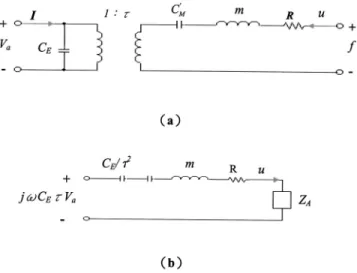
. 共44兲As evidenced from the symmetric impedance matrix, the pi-ezoelectric radiator is a ‘‘reciprocal’’ transducer. With ad hoc damping introduced, the electromechanical equivalent circuit is shown in Fig. 2共a兲. Reflecting the electrical side to the mechanical side gives Fig. 2共b兲, where
CM
⬘
⫽ CM1⫺K2, 共45兲
and K⫽
冑
␣2CMCE being the coupling factor. From theequivalent circuit, the frequency response between the modal velocity and the applied voltage can be expressed as
u Va ⫽ 共 j兲 2C E 共 j兲2m⫹共 j兲共R⫹Z A兲⫹ 1 CT , 共46兲
where CT⫽CECM
⬘
/(CE⫹2CM⬘
) and R⫽2m冑
1/mCT, with being the damping ratio. This single-mode approximation is apparently a second-order system with the natural fre-quency,
0⫽
冑
mC1T
, 共47兲
and a gain beyond resonance g⬁⫽
冏
uVa
冏
⬇CE
m , Ⰷ0. 共48兲
An example of the single-mode frequency response of the piezoelectric radiator is illustrated in Fig. 3. For good perfor-mance, it is desirable for the resulting design of the radiator to have a low natural frequency 0 and high gain g⬁. III. OPTIMAL DESIGN VIA THE GENETIC ALGORITHM
The genetic algorithm共GA兲 is an optimization algorithm that is originally motivated by natural selection and evolu-tionary genetics.9The GA has proven to be efficient in many areas such as function optimization and image processing. Unlike the conventional gradient search algorithms, the GA
requires no calculation of the gradient and is not susceptible to problems of local minima. In each ‘‘generation,’’ three basic genetic operators, reproduction, crossover, and muta-tion, are performed to generate a new population and fitness functions of the chromosomes of the population are evalu-ated. An optimal solution is then obtained, according to the principle of ‘‘survival of the fittest.’’ The GA procedure ap-plied to design the piezoelectric radiator is detailed as fol-lows.
A. Fitness function
Fitness is a measure of the survival rate of a chromo-some. A chromosome with high fitness has a high probability of reproducing one or more offspring in the next generation. The ratio of the gain and the natural frequency of the single-mode approximation serves as the fitness function for the GA optimization: fc⫽ g⬁ 0⫽ CE m 1
冑
mCT ⫽␣CE2冑
CT m. 共49兲The goal of optimization is to search for a design with a low natural frequency and a high gain by maximizing the fitness function fc. In the single-mode system, parameters relevant to the optimization are
m⫽p, 共50兲 CE⫽ 1 ⫽ LcWc tc33 S , 共51兲 CT⫽ CEC
⬘
M CE⫹2CM⬘
⫽CM⫽ 1 k, 共52兲 ␣⫽⫺6h31共tptc⫹tc 2兲冑
LcWc冋冉
1 Lc2⫹ 1 Wc2冊
cos x1 Lc cosy1 Wc册
, 共53兲 kt⫽4冋
D⫹冉
1 2tp 2t c⫹tptc 2⫹2 3tc 3冊
c 11 D册
冉
1 Lc4⫹ 1 Wc4⫹ 2 Lc2Wc2冊
. 共54兲 The symbols tp and tc are the thickness of the panel andPZT, respectively. Substituting Eqs. 共50兲–共53兲 into Eq. 共49兲 gives fc⫽␣CE 2
冑
CT m⫽ tp⫹tc tt LcWc 1冑
k, 共55兲 where ⫽⫺6h31 33 S冑
LcWc m冉
1 Lc2⫹ 1 Wc2冊
cos x1 Lc cosy1 Wc . 共56兲 When 0⭐x1⭐Wp/2 and 0⭐x2⭐Lp/2, is a positivecon-stant. It can be readily verified that
fc/Lc⬎0, 共57兲
fc/Wc⬎0, 共58兲
FIG. 2. Electromechanical equivalent circuits of the piezoelectric panel ra-diator.共a兲 The electromechanical equivalent circuit; 共b兲 the equivalent cir-cuit referred to as the mechanical side.
FIG. 3. The example of the single-mode frequency response of the piezo-electric panel radiator.0is the natural frequency and g⬁is the gain beyond
fc/tc⬍0. 共59兲
Thus, fc is a monotonically increasing function of Lc and
Wc, and a monotonically decreasing function of tc. That is,
it is generally preferable to have a design using a large and thin PZT, provided no other constraints are of concern. In what follows, the parameter Lc, Wc, and tcwill not be
op-timized, but were constrained in a certain prescribed range. B. Encoding and decoding
Suppose that the position of the PZT, (x1,y1), on the
panel are to be optimized. The variables x1 and y1 are
en-coded into a binary string of length li, called a chromosome.
The resolution for the string of such length is Ri⫽
xiU⫺xiL
2li⫺1 , 共60兲
where xiU and xiL are the upper and lower limits of the pa-rameter. For example, if 0⬍x1⬍4.5 mm, 0⬍y1⬍3.5 mm, and the desired resolutions are R1⫽0.145 and R2⫽0.113, then l1⫽l2⫽5. If x1⫽1.595 and y1⫽1.468, then the chro-mosome is encoded as关01011 01101兴.
C. Reproduction, crossover, and mutation
Reproduction directs the search of GA toward the best individuals. The chromosome of the current population is reproduced in the next generation according to the reproduc-tion probability pi, pi⫽ fc 兺1 Pl fc , 共61兲
where Pl is the population size. Assume there are four
chro-mosomes, c1– c4, in the zero generation with fitness
func-tions 17, 33, 47, and 69. From Eq. 共61兲, the reproduction probabilities are p1⫽0.102, p2⫽0.199, p3⫽0.283, and p4
⫽0.416, respectively. The chromosome c4is the most likely
to reproduce in the next generation. These four reproduction probabilities are then concatenated in the real line, as shown in Fig. 4. In the first generation, four random numbers be-tween 0 and 1 are generated. For example, if the generated random numbers are 0.812, 0.666, 0.111, and 0.501, the can-didate chromosomes for reproduction in the next generation will be c4, c4, c2, and c3, respectively.
Crossover is intended to exchange the information be-tween chromosomes via a probabilistic decision in the mat-ing pool. It proceeds in three steps. First, the crossover rate pc is specified 共usually 0.8⬍pc⬍1, and we choose pc
⫽0.9). Two chromosomes in the mating pool are selected to cross over at random. Precisely, the entire population in each
generation is divided into pairs, e.g., 100 pairs would be required for 200 chromosomes. For each pair, a random number between 0 and 1 is then generated. If the random number is less than the crossover rate pc, the crossover
pro-cedure will take place. Second, a splice point at the chromo-some is selected randomly. Third, the genetic codes after the splice point are interchanged. For example, there are two chromosomes c1and c2with the splice point at the third bit: c1⫽010⌬1010, c2⫽111⌬1111. With crossover, two new chromosomes are generated: c˜1⫽010⌬1111, c˜2⫽111⌬1010.
Reproduction and crossover provide the most search power for GA. However, the gene becomes increasingly ho-mogeneous as one gene begins to dominate after several gen-erations and eventually results in premature convergence. To obviate this problem, mutation is introduced into the GA procedure. Let the probability of mutation be pm 共usually 0
⬍pm⬍0.01, and we choose pm⫽0.01). This probability
de-termines how many genes are selected for mutation in each generation. In this analysis, where the population was chosen to be 200 at the given 0.01 mutation rate, approximately two genes were presumably selected for mutation in each genera-tion. Mutation is carried out by alternating the gene from zero to one, or from one to zero, with the mutation point determined randomly. For instance, a chromosome c3 with
the mutation point at the third bit is c˜3⫽10 0
⌬
101010. After mutation, the chromosome becomes c˜3⫽10 1
⌬
101010. Note, however, that mutation should be used sparingly. The GA would behave like a random search if the mutation rate is too high.
The aforementioned GA procedure was applied to the design of the piezoelectric radiator. The parameters to opti-mize include the positions of the PZT and the Young’s modu-lus of the panel. Two kinds of thickness共100 and 150 m兲 and five kinds of aspect ratio were examined in the optimi-zation. The results of optimal PZT positions on the panel are
FIG. 4. The reproduction probabilities of four chromosomes, c1– c4, with
fitness functions, 17, 33, 47, and 69, are concatenated in a real line.
TABLE I. The results of optimal PZT positions on the panel obtained using the GA procedure. Every entry in the table includes three values: the gain beyond resonance, the natural frequency, and the optimal position of the PZT. The thickness of PZT 100m 150m Aspect ratio (length⫽1.5 cm) 1:共1/3兲 ⫺179.520 dB ⫺181.886 dB 147.461 Hz 179.076 Hz 共1 cm, 2.75 cm兲 共1 cm, 2.81 cm兲 1:共1/2兲 ⫺172.512 dB ⫺174.870 dB 163.710 Hz 205.458 Hz 共1 cm, 2.65 cm兲 共1 cm, 2.61 cm兲 1:1 ⫺160.639 dB ⫺163.003 dB 202.512 Hz 265.580 Hz 共1 cm, 2.27 cm兲 共1 cm, 2.32 cm兲 1:2 ⫺149.287 dB ⫺151.643 dB 248.890 Hz 335.386 Hz 共1 cm, 1.46 cm兲 共1 cm, 1.5 cm兲 1:3 ⫺143.437 dB ⫺145.812 dB 265.826 Hz 359.739 Hz 共1 cm, 0.75 cm兲 共1 cm, 0.78 cm兲
summarized in Table I. Every entry in the table includes three values: the gain beyond resonance, the natural fre-quency, and the optimal position of the PZT. The optimal Young’s moduli of the panel are found to vary between 9 and 13 GPa.
IV. NUMERICAL SIMULATION
Although the assumed-modes method, in principle, is applicable to general cases, the modes we assumed are re-stricted to the eigenfunctions of a simply supported plate that are simple enough for a practical calculation during optimi-zation. The simply supported boundary conditions are
w共0,y兲⫽w共Lp,y兲⫽ 2w x2共0,y兲⫽ 2w x2 共Lp,y兲⫽0, 0⭐y⭐Wp, 共62兲 w共x,0兲⫽w共x,Wp兲⫽ 2w y2共x,0兲⫽ 2w y2共x,Wp兲⫽0, 0⭐x⭐Lp. 共63兲
The associated eigenfunctions are
mn共x,y兲⫽ 2
冑
LpWp sinmx Lp sinny Wp . 共64兲The natural frequencies are
mn⫽
冑
D p 2冉
m 2 Lc2⫹ n2 Wc2冊
. 共65兲Suppose that only M most significant modes are retained in the series expansion. A M⫻M transformation matrix ⌽ can be constructed by dividing the panel into M grid points:
⌽⫽ 2
冑
LpWp冋
1 N1sin m1x1 Lp sin n1y1 Wp ¯ 1 NMsin mMx1 Lp sin nMy1 Wp ] ] 1 N1sin m1xM Lp sin n1yM Wp ¯ 1 NMsin mMxM Lp sin nMyM Wp册
, 共66兲where Ni is the norm of the ith column. Hence, the modal
radiation impedance Z˜A is obtained using Eq. 共31兲. The modal velocity vector v˜ is obtained by solving Eq.共33兲. The velocity in physical space is then obtained from Eq.共29兲.
For radiators in a planar baffle, the propagation matrix E can be written as8 E⫽ j0cskA 2
冤
e⫺ jkr11 r11 e⫺ jkr12 r12 ¯ e⫺ jkr1n r1n e⫺ jkr21 r21 e⫺ jkr22 r22 ¯ e⫺ jkr2n r2n ] ] ] e⫺ jkrm1 rm1 e⫺ jkrm2 rm2 ¯ e⫺ jkrmn rmn冥
, 共67兲where A is the area of each element and rmn is the distance
from the element n to the field point m. Using the matrix E, we can calculate the farfield pressure,
pf⫽Ev, 共68兲
where v is the surface velocity vector on the panel.
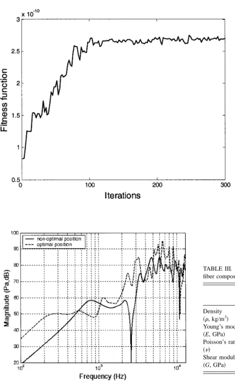
The data of the PZT and the panel in our simulation are shown in Table II. The dimensions of the panel are 45 mm ⫻35 mm⫻0.1 mm, which are close to those of a cellular phone. Assume that the panel material is polycarbonate共PC兲. The size of the PZT is 15 mm⫻30 mm⫻0.1 mm. Using the GA procedure with a population size 200, the optimal posi-tion of the PZT on the PC panel was found to be at 共10.0 mm, 14.6 mm兲. The learning curve of the GA is shown in Fig. 5. With approximately 100 iterations, the fitness
func-tion settles to 2.6⫻10⫺10. The computation time was nearly 4 hours for 300 iterations on a Pentium 4 personal computer. The frequency responses for the optimal position and a non-optimal position 共15.0 mm, 10.0 mm兲 of the PZT, of the on-axis sound pressure at a point 0.5 m away from the panel, were calculated using the forgoing numerical model and compared in Fig. 6. The configuration with the optimal PZT position exhibits significantly better low-frequency response and high-frequency gain as well.
V. EXPERIMENTAL INVESTIGATION
Experiments were undertaken to verify the proposed op-timal designs of the piezoelectric panel radiators. Two kinds of panel materials, the polycarbonate and the carbon fiber composite material, are used in the experiment. The param-eters of panel materials are listed in Table III. A PU foam and TABLE II. The data of the PZT and the panel used in the simulation. The dimensions of the panel are 45 mm⫻35 mm⫻0.1 mm.
Parameter Value
PC plate Size 0.045 m⫻0.035 m⫻0.00025 m
Density 1200 kg/m3
Young’s modulus 2.7 GPa Poisson’s ratio 0.97 PZT Size 0.0015 m⫻0.0030 m⫻0.0001 m 33 S 1.94⫻108 h ⫺8.1⫻108 V/m c11 D 11.73⫻1010N/m2 c12 D 7.77⫻1010N/m2 c66 D 1.98⫻1010N/m2
FIG. 5. The learning curve of the GA. With approxi-mately 100 iterations, the fitness function settles to 2.6
⫻10⫺10. The computation time was nearly 4 h for 300
iterations on a Pentium 4 personal computer.
FIG. 6. The simulated on-axis frequency responses for two positions of the PZT, at a point 0.5 m away from the panel. The size of the panel is 45 mm⫻35 mm⫻0.25 mm. The size of the PZT is 15 mm⫻30 mm
⫻0.1 mm. The optimal position of the PZT is at 共10.0 mm, 14.6 mm兲. The
nonoptimal position of the PZT is at共15.0 mm, 10.0 mm兲.
TABLE III. The parameters of the polycarbonate material and the carbon fiber composite material.
Polycarbonate
共PC兲
Carbon fiber composite material Density 共, kg/m3兲 1200 1546.37 Young’s modulus 共E, GPa兲 2.7 E1⫽147.564, E2⫽9.314 Poisson’s ratio 共兲 0.97 0.283 Shear modulus 共G, GPa兲 0.42 5.702
TABLE IV. Configurations of piezoelectric radiators investigated in the experiment. Two kinds of suspensions, a PU foam and a plastic tape, are tested.
No. of panel T size 共mm兲 Panel size 共mm兲 Material of plate Material of BC PZT position No. 1 15⫻30⫻0.1 45⫻35⫻0.25 PC PU foam (t⫽1 mm) Nonoptimal: 共15.0 mm, 10.0 mm兲 No. 2 15⫻30⫻0.1 45⫻35⫻0.25 PC PU foam (t⫽1 mm) Optimal: 共10.0 mm, 14.6 mm兲
No. 3 15⫻30⫻0.1 45⫻35⫻0.25 Carbon fiber (0°⫻2)
PU foam (t⫽1 mm)
Optimal:
共10.0 mm, 14.6 mm兲
No. 4 15⫻30⫻0.1 45⫻35⫻0.25 Carbon fiber (0°⫻2)
Adhesive tape
Optimal:
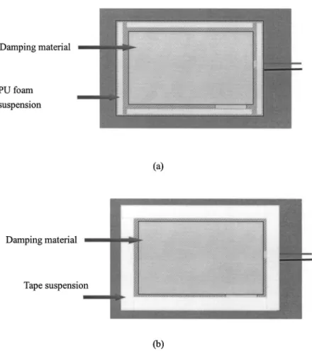
a plastic tape, representing a hard suspension and a soft sus-pension, are tested. The suspensions are sealed all around the boundary of the panels. With an appropriate combination of these conditions, four configurations of piezoelectric radia-tors were investigated in the experiment, as summarized in Table IV. The implemented piezoelectric panel radiators are
schematically shown in Fig. 7. The panels were treated with some damping. Figure 8 shows the photo of the radiator No. 2. All radiators were embedded in a baffle while testing. The experimental arrangement is shown in Fig. 9. The perfor-mance of the panel radiators are measured in an anechoic room and summarized as follows.
FIG. 7. Illustrations of the piezoelectric radiators.共a兲 Nos. 1, 2 and 3;共b兲 No. 4.
A. Frequency responses of farfield pressure
The on-axis pressure responses at 0.5 m from panel speaker were measured. A random signal of 30 V rms, band-limited to 12.8 kHz was used as the input. Figures 10–12 illustrate the performance of various designs. Figure 10 shows the effect of the PZT positions. The design using the optimal position 共No. 2兲 of the PZT produced a better
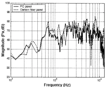
low-frequency response than that using a nonoptimal position 共No. 1兲. In Fig. 11, the frequency responses of the panel radiators, No. 2 and No. 3, are compared. The Young’s modulus of the carbon fiber is close to the optimal value obtained from GA. The sound pressure level of the carbon fiber panel is higher than that produced by PC above 700 Hz, which results in a ‘‘brighter’’ sound quality of the carbon fiber radiator than the PC. In Fig. 12, we see the frequency responses of panel radiator No. 3 and No. 4. From the result, FIG. 9. The experimental arrangement for the perfor-mance measurement of the piezoelectric panel radia-tors. The measurement was conducted in an anechoic room.
FIG. 10. The frequency responses of the panel radiators Nos. 1 and 2. The effect of the PZT positions on the panel is investigated. The design using the optimal position of the PZT produced a better low-frequency response than that using a nonoptimal position.
FIG. 11. The frequency responses of the panel radiators, Nos. 2 and 3. The effect of Young’s modulus is investigated. The Young’s modulus of the carbon fiber is close to the optimal value obtained from GA. The sound pressure level of the carbon fiber panel is higher than that produced by PC above 700 Hz.
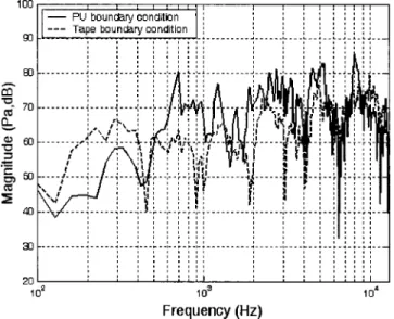
the profound effect of the boundary condition is also evi-denced. With the soft suspension, the low-frequency response is enhanced at the expense of the high-frequency output.
B. Sensitivity
Sound pressure level is measured on-axis at the distance 0.5 m from the radiator, under the free-field condition. The input signal is the random noise of 30 V rms, bandlimited to 12.8 kHz, which amounts to the input electric power 0.018 W. The measured sensitivities of the No. 3 panel radiator is 76 dB. With this level of acoustic output, speech and music are found to be quite intelligible, even at 1 m distance.
C. Efficiency
The efficiency is defined as the ratio of the radiated acoustical power to the input electrical power. The input electrical power is calculated as
Win⬇ 1 2i
兺
⫽1 N 兩V兩2Re共Z兲 兩Z兩2 ⌬ f ⫽ 1 2兺
i⫽1 N PRe冉
1 Z冊
⌬ f , 共69兲 where V and Z are the Fourier transforms of the input voltage and the electrical impedance. P is the power spectral den-sity of the input voltage.In this work, ISO 3745 was employed for measuring the radiated sound power in the anechoic room.10The measured efficiency of the No. 3 radiator was 0.767%. In order to appreciate this performance, a panel radiator using identical configurations, except a voice-coil exciter is used, was tested for comparison. The measured efficiency of the radiator driven by the voice-coil exciter was 0.075%. This impressive result indicates that the piezoelectric panel radiator is a very efficient device, which is indeed an attractive feature for many a power-saving applications.
D. Directional response
The directional response11 of the panel radiator was measured by mounting the radiator on an automated turn-table driven by a stepper motor. A 1/2 in. condenser micro-phone is placed at the distance 0.5 m from the radiator to measure the generated sound pressure under a free-field con-dition. The panel radiator was rotated at angles from 0° to 180°, with 1° increments. Random noise of 30 V rms, band-limited to 12.8 kHz, served as the input. The measured re-sults of directional response are shown in Fig. 13. The rere-sults indicate that the panel radiator has a relatively omnidirec-tional response. However, the direcomnidirec-tional responses are not symmetrical because the PZT is not mounted at the center position.
FIG. 12. The frequency responses of the panel radiator Nos. 3 and 4. The effect of the boundary condition is investigated. With a softer suspension, the low-frequency response is enhanced at the expense of the high-frequency output.
FIG. 13. Directional responses of the piezoelectric ra-diators at 500, 1, 2 and 4 kHz. The thick line at the center symbolizes the position of the panel.
VI. CONCLUSIONS
A piezoelectric radiator has been proposed in this paper. Although piezoelectrically driven radiators have been around for some time, these devices mainly exist in the form of narrow band acoustic radiators such as buzzers, sounders, sirens, etc., where sound quality is generally not of major concern. By contrast, this work developed an acoustic radia-tor for a different aim: to meet quality loudspeaker require-ments with regard to speech and music listening. The reason why we used piezoelectricity as the driving mechanism lies in our emphasis on the 3C applications, where space and power consumption is critical.
Dynamic modeling of the system was carried out using the energy method and the assumed-modes method. A more elaborate approach than other study is exploited in modeling the acoustic loading and the model is established as a fully coupled system, which is important for a light structure con-sidered here in the paper. Discretization is simplified by as-suming a series expansion in energy terms, but not in partial differential equations. The assumed-modes method is em-ployed in the series expansion such that the ensuing optimi-zation process can be carried out in an efficient and practical way.
In this paper we seek to attain an optimal design of the piezoelectric panel speaker, using a ‘‘synergetic’’ approach. In particular, a nonconventional optimization algorithm, GA, was employed in this paper to effectively tackle this noncon-vex problem. The GA is a multiple starting point algorithm and is not susceptible to the problem of local minima. Per-formance and adequacy as a broadband loudspeaker of the proposed device is thoroughly investigated. As confirmed by the numerical and experimental results of various indices, the piezoelectric radiator using the optimal configuration indeed produced better performance than the nonoptimal ones. The suspension, the material of the panel, and the mounting po-sitions of PZT are important factors that may contribute to the performance of the radiators. The optimal combination of these parameters can be jointly considered in the GA procedure.
From the experimental investigation, the piezoelectric radiators produced quite impressive efficiency 共approxi-mately 10:1兲 over the panel speakers driven by voice-coil exciters. Furthermore, the thickness of present design of the piezoelectric radiator is 0.35 mm, which is significantly less than the 2.4 mm of the voice-coil panel speaker. In compari-son with other conventional means, the piezoelectric radia-tors are found promising in meeting the increasingly strin-gent requirements of 3C products.
ACKNOWLEDGMENTS
Thanks are due to the illuminating discussions with NXT, New Transducers Ltd., UK. The work was supported by the National Science Council (NSC) in Taiwan, under Project No. NSC 89-2212-E009-057. Special thanks also go to Dr. Meng-Shiun Tsai in Chong-Cheng University for his helpful suggestions on derivations of piezoelectric plates.
1M. R. Bai and T. Huang, ‘‘Development of panel loudspeaker system: Design, evaluation and enhancement,’’ J. Acoust. Soc. Am. 109, 2751– 2761共2001兲.
2H. Azima, ‘‘NXT up against wall,’’ Audio Magazine 34 – 41共Sept., 1998兲. 3J. G. Smits, S. I. Dalke, and T. K. Cooney, ‘‘The constituent equations of
piezoelectric bimorphs,’’ Sens. Actuators 28, 41– 61共1991兲. 4
J. W. Waanders, Piezoelectric ceramics—Properties and Applications 共Philips Components Eindhoven, The Netherlands, 1991兲.
5H. L. Langhaar, Energy Methods in Applied Mechanics共Wiley, New York, 1962兲.
6
H. F. Tiersten, Linear Piezoelectric Plate Vibration共Plenum, New York, 1969兲.
7L. Meirovitch, Elements of Vibration Analysis共McGraw-Hill, New York, 1986兲.
8A. P. Berkhoff, ‘‘Sensor scheme design for active structural acoustic con-trol,’’ J. Acoust. Soc. Am. 108, 1037–1045共2000兲.
9J. H. Holland, ‘‘Outline for a logical theory of adaptive system,’’ J. Assoc. Comput. Mach. 3, 297–314共1962兲.
10ISO 3745, ‘‘Acoustics—Determination of sound power levels of noise sources—Precision methods for anechoic and semi-anechoic rooms,’’ 1977.