A Novel Adaptive Antenna Array for DS/CDMA
Code Acquisition
Hua-Lung Yang and Wen-Rong Wu
Abstract—Equipped with an adaptive beamformer, existing adaptive array code acquisition still relies on the correlator struc-ture. Due to the inherent property of the associated serial-search scheme, its mean acquisition time is large, especially in strong interference environments. In this paper, we propose a novel adaptive filtering scheme to solve the problem. The proposed scheme comprises two adaptive filters, an adaptive spatial and an adaptive temporal filter. With a specially designed structure, the spatial filter can act as a beamformer suppressing interference, while the temporal filter can act as a code-delay estimator. A mean squared error (MSE) criterion is proposed such that these filters can be simultaneously adjusted by a stochastic gradient descent method. The performance as well as the convergence behavior of the proposed algorithm are analyzed in detail. Closed-form expressions for optimum filter weights, optimum beamformer signal-to-interference-plus-noise ratio (SINR), steady-state MSE, and mean acquisition time are derived for the additive white Gaussian noise (AWGN) channel. Computer simulations show that the mean acquisition time of the proposed algorithm is much shorter than that of the correlator-based approach, and the derived theoretical expressions are accurate.
Index Terms—Adaptive filter, antenna array, code acquisition, code-division multiple access, multipath, multiple-access interfer-ence.
I. INTRODUCTION
D
IRECT-SEQUENCE/code-division multiple access (DS/CDMA) is a promising technique for wireless mobile communication. It is well known that the main performance bottleneck for a CDMA system is the multiple access interfer-ence (MAI). MAI affects not only data detection but also code acquisition. Code acquisition is a coarse code synchronization process, aligning the received signal and the local code se-quence with an error less than a chip duration. After successful code acquisition, other operations such as channel estimation, code tracking, and data detection can follow. Thus, code acqui-sition is a critical task in DS/CDMA systems. With an antenna array, the performance of code acquisition can be effectively enhanced. In this paper, we consider code acquisition with adaptive antenna arrays.Code acquisition with a single antenna has been widely studied [1]–[12] (and references therein). The correlator ap-proach [1]–[5] is most well known. However, the correlator is only optimal for the single-user case. Its performance de-grades significantly while MAI presents especially at near–far environments [5]. Subspace- or matrix-based methods [6], [7] Manuscript received August 28, 2006. The associate editor coordinating the review of this letter and approving it for publication was Dr. Kostas Berberidis. The authors are with the Department of Communication Engineering, Na-tional Chiao Tung University, Hsinchu, Taiwan, R.O.C. (e-mail: hualungyang. [email protected]; [email protected]).
Digital Object Identifier 10.1109/TSP.2007.893916
have been developed to solve the problem. The advantage of subspace-based approaches is that no training sequences are required and the performance is much better than that of the correlator scheme. However, these methods usually have to es-timate, decompose, or inverse the autocorrelation matrix of the received signal vector. This often requires high computational complexity, especially for systems with large processing gains. Recently, adaptive filtering has been introduced to code acquisition [8]–[12]. The adaptive filter proposed in [8] and [12] uses the desired user’s pseudonoise (PN) sequence as input and the received signal as reference and finds the code-delay from the location of the maximum convergent tap-weight. It is claimed that [8] the adaptive filtering approach can pro-vide higher acquisition-based capacity [4] compared to the correlator scheme. The acquisition-based capacity indicates the maximal number of users that a system can serve under a given acquisition error rate. Yet, another adaptive receiver structure reported in [11] performs an exhaustive search to find the integer chip delay and then solves quadratic equations to find the corresponding fractional chip delay. The drawback of this approach is that its computational complexity is high, particularly for systems with large processing gains and large delay uncertainty. In [12], a low computational complexity adaptive-filtering scheme for large delay uncertainty was re-ported.
As mentioned, antenna arrays can be used to enhance ac-quisition performance [13]–[17]. In [13], each array element is equipped with a correlator, and the correlator outputs are used as the input to a beamformer. If an assumed code-phase is correct, the output of the optimum beamformer will exceed a preset threshold. Then, acquisition is claimed. Otherwise, the code-phase is changed and optimum beamformer weights are recalculated. A frequently considered MAI scenario is called directional MAI, in which MAI signals arrive at the array in some incident angles. When the interference is present, direct matrix inversion is needed to derive the optimum beamformer weights [13]. In [14], an adaptive beamformer is used to avoid this problem. However, the beamformer has to converge for each trial code-phase. It requires a long adaptation time in an MAI environment, and acquisition is then slow. The approach in [17] uses a simple noncoherent correlator performing a two-di-mensional search. This method serially searches a cell corre-sponding to a specified delay and an angular region. Since the search is performed in two dimensions, it often requires longer mean acquisition time if better angular resolution is desired. In addition, the acquisition performance degrades when directional interference exists, as addressed in [17] and [18]. A remedy with an additional algorithm was proposed in [18]. Apart from that, there are approaches treating acquisition as a channel estimation problem [19]–[24]. These methods provide good performance and usually require matrix computations that are not desirable 1053-587X/$25.00 © 2007 IEEE
in real-world implementation. In [25] and [26], a correlator bank exploiting multipath signals was used for acquisition. However, its structure is quite complicated.
In this paper, we propose a novel scheme for code acquisition with antenna array. The proposed algorithm belongs to the cate-gory of the adaptive filtering approach. It can be applied in either periodic or aperiodic code systems. The proposed scheme con-tains two adaptive filters: a spatial and a temporal filter. A mean squared error (MSE) criterion is proposed such that both filters can be simultaneously adjusted by a stochastic gradient descent algorithm, called the constrained least mean square (LMS) al-gorithm. The spatial filter acts as a beamformer to suppress in-terference while the temporal filter acts as a channel estimator identifying the code-delay. The proposed scheme can form a beam pattern with multiple main beams collecting the desired user’s multipath signals from different directions. We also an-alyze the signal-to-(interference plus noise) ratio (SINR) at the beamformer output, probability of correct acquisition, and mean acquisition time, and derive closed-from expressions for the ad-ditive white Gaussian noise (AWGN) channel. The proposed scheme can deal with fractional code-delay, which is not consid-ered in [13]–[17]. Also, the temporal filter can estimate channel responses of the desired user.
This paper is organized as follows. Section II describes the adaptive array acquisition approach in [14]. Section III develops the proposed schemes for various channel scenarios. Section IV discusses issues of adaptive processing, and Section V carries out performance analysis. Section VI presents simulation re-sults demonstrating the effectiveness of the proposed scheme. Finally, Section VII gives conclusions. Throughout this paper, we use , , and to denote an identity matrix, a vector two-norm, and a statistical expectation operator, respectively. Note that the dimension of is not explicitly shown; it will be defined whenever necessary. Also, let and , , and denote the conjugate, transpose, and Hermitian oper-ator, respectively.
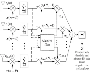
II. CORRELATOR-BASEDADAPTIVEARRAYCODEACQUISITION In this section, we briefly review the adaptive array approach in [14], which is a single-dwell serial search method. The block diagram of this approach is shown in Fig. 1. As seen, it has an antenna array with sensors and uses an individual correlator (or accumulator) for each array element. It is assumed that the array is linear and the sensors are uniformly placed. Also, the element spacing is half a wavelength. The chip-rate sampled received signal vector in baseband is given by
(1) where is the PN code sequence of the desired user (i.e., no data are modulated for the desired user during acquisition), is the carrier-phase offset, is the cor-responding code-delay assumed to be an integer form zero to 1, where is the processing gain, and is a zero-mean complex and white Gaussian noise vector associated with a covariance matrix of . Note that consists of MAI and noise. When the number of interfering users and the number of resolvable multipaths are large, the Gaussian assumption is generally held. The steering vector in (1) is given by , where denotes the direction of arrival (DoA) of the desired user.
Fig. 1. Correlator-based adaptive array code acquisition system;w (N 0 1) [wc; 0; . . . ; w ] .
For a trial code-phase , the output of the th correlator can be obtained as
(2) where is the th element in and is the pro-cessing period for each code-phase, selected as 2 in [14]. Let
and
(3) Then (3) is used as the input to an -tap adaptive filter, . Consider a specific processing period and let be the starting instant for filter adaptation . Define a cost
function of , where .
Using the method of stochastic gradient descent, we can then have the update equation for as
(4) where is the step size controlling the convergence rate. The filter-weight vector is then used for constructing the
testing statistic (see Fig. 1). If
exceeds a preset threshold, the system will claim the acqui-sition and enter the code-tracking phase. Otherwise, the system will advance the trial code-phase and repeat the process all over again. As indicated in [29], the step size is bounded in the range of zero and 2 , where is the correlation matrix of and is the trace operation. In [14], 1 was chosen as a compromise between the convergence rate and stability.
Let the trial code-phase be . If , the decision variable will have a noncentral chi-square distribution. By contrast, if , the decision variable will have a central chi-square dis-tribution. Let be the threshold for the acquisition claim. Then, we can have the probability of false alarm and the probability of correct detection . Since the false alarm is more harmful
to the mean acquisition time, is usually fixed to some level (e.g., ) and the threshold can be calculated accord-ingly. Finally, the mean acquisition time, denoted as , can be determined as [14]
(5) where is the penalty factor and the unit for (5) is chip. Note that if there is no directional interference and the signal-to-noise ratio (SNR) is high, will converge to the steering vector of the desired user. If the adaptive filter is initialized with , the filter will converge rapidly since each element in the optimum filter-weight is just a phase-rotated version of that in . However, if directional interference exists, the relationship cannot be held and the convergence of the adaptive filter becomes slow. As a result, the mean acqui-sition time becomes large (shown in Section VI), especially at strong interference environments.
III. PROPOSEDADAPTIVEANTENNACODEACQUISITION
A. Signal Model and Algorithm Development
Assume that there are users in a cell and each user is given an aperiodic PN sequence. Aperiodic code means its period is much longer than a symbol period [19], [27]–[28]. The contin-uously transmitted signal of the th user in baseband can be ex-pressed as
(6) where is the th binary phase-shift keying symbol of the th user, the th chip of the spreading code (assumed to be random) for , and a unit-amplitude rectangular pulse with a chip duration . Also, let the channel associated with the th user have paths, and the DoA for each path may be different. Then, the chip-rate sampled received signal vector can be represented as
(7) where
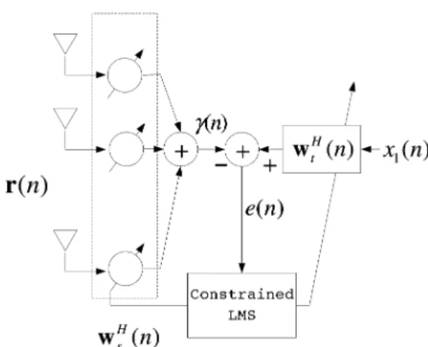
(8) is an 1 complex Gaussian vector with zero mean and a covariance matrix of , and , , , and denote the code-delay, steering vector, complex channel gain, and carrier-phase offset associated with the th channel path of the th user, respectively. Note that is uniformly distributed over and is given by , where is the DoA for the th channel path of the th user. Fig. 2 illustrates the structure of the proposed scheme. Without loss of generality, the first user is seen as the desired user. As seen, there are two adaptive filters: a spatial and a cascaded temporal filter. The spatial filter combines the array outputs
Fig. 2. Proposed adaptive array code acquisition system.
into a single output. The temporal filter uses as its input signal and the spatial filter output as its reference signal. Note here that is the same as the PN code sequence of the desired user, , since during the acquisition period. In what follows, we will use to denote the PN code sequence of the desired user as well. The spatial filter acts like a beamformer to reject interference, while the temporal filter acts like a channel estimator to estimate the beamformed temporal channel of the desired user. The code-delay can then be estimated from the peak position of . The difference between these two filter outputs forms the error signal from which we can perform filter adaptation. We propose a cost function as
(9)
where , ,
and . Note that
the function of the beamformer is to suppress interference and in the ideal case, its output will consist of the beam-formed signal of the desired user and noise. On the other hand, the function of the channel estimator is to identify the beam-formed channel and in the ideal case, its output can form the same beam-formed signal. Thus, minimization of (9) will let and have the solutions we desire.
Notice that the filter size of should be larger than or equal to the delay uncertainty assumed to be here. From (9), it is simple to find that a minimum (which is zero) occurs when and , and this is an undesired trivial solution. To avoid that, we pose a unit-norm constraint on the solution. That is
(10) As a result, (9) becomes a constrained optimization problem. We use the Lagrange multiplier method [29] to transform the con-strained optimization problem into an unconcon-strained one. From (9) and (10), we have an equivalent cost function as
where
(12)
, ,
and denotes the Lagrange multiplier. Differentiating (11) with respect to and and setting the results to be zero-vectors, we can obtain
(13) (14) Since is a full-rank matrix, its matrix inversion exists. From (13), we have
(15) Substituting (15) into (14), we have
(16) It is simple to see that the solution of is an eigenvalue of
, while is the corresponding eigenvector. Note that an eigenvector satisfies the constraint in (10) automatically. Once is derived, can be found using (15). Multiplying (16) with , we obtain
(17) Substituting (15) into (11) and using (17), we have
(18) Let the solutions to (13) and (14), which are optimum weights, be denoted as and and the corresponding minimum value of (11) be . From (18), we can conclude that is equal to the minimum eigenvalue of , and is the corresponding eigenvector. Substituting into (15), we can then obtain . In the sequel, we will apply this result to find and in various channel scenarios.
B. Code Acquisition With AWGN Channel
In this section, we consider the AWGN channel scenario. In other words, for in (7). For convenience, we drop the subscript in (7). The received signal can be written as
(19)
where we let , , , , and
.
Here, we let the code-delays of all users have fractional parts. For the desired user, we let
(20) where is an integer, , and is a real number, . Also, let . From (8), we can write the received signal of the desired user as [6], [7], [20]
(21) Note that (21) is a weighted sum of with two successive code-delays and 1. This is because and a complete received chip in the chip-matched filter crosses two successive chip-intervals. Using (21), we can rewrite (19) as
(22) Substituting (22) into (12), we find
(23)
where and are in the
( 1)th and ( 2)th row of , respectively. We then apply (23) to (16) and then obtain (24) as shown at the bottom of the page, where we have assumed that (long-code
..
. ...
..
. ...
assumption) and defined
(25) (26)
Now, we can see that there are two nonunity columns in (24) and they are located in the ( 1)th and ( 2)th columns. To derive the eigenvalue , we let
(27) where stands for the determine of a matrix. Then, we have
(28) It is simple to see that there are roots for (28) and only one is nonunity. Its value is 1 1 . Since both 1
and are positive, the nonunity eigenvalue is positive and smaller than one. Thus, it is the minimum eigenvalue. Denoting it as , we have
(29) Note that the terms in the bracket of (29) are maximized when . Substituting back to (16), we can solve the corre-sponding eigenvector as
(30) Equation (30) implies that is in the null space of
, where see have (31) as shown at the bottom of the page. Note that the ( 1)th and ( 2)th rows in (31) are linearly dependent. Thus, is with a rank of 1. Substituting (31) into (30), we obtain
(32) (33) (34)
where denotes the th element of and . Thus, we have
(35)
where is an arbitrary angle. With the peak position in (35), it is simple to see that the code-delay is correctly acquired. As we can see, does not have a unique solution. The nonunique-ness of the optimum solution stems from the fact that (10) is only an amplitude constraint. Even though the solution is nonunique, it does no harm to our solution since only the amplitude is used in peak finding. Now, let us solve . Using (35) and (23) in (15), we can derive
(36) As we can see from (36), corresponds to the conventional minimum mean squared error (MMSE) beamformer . Notably, we can estimate the fractional delay from [see (35)] as
(37)
A special case considered most in the literature (e.g., [8] and [13]–[17]) is that (integer delay). In this case, the results shown above can be further simplified. Substituting into (29), (35), and (36), we then obtain ,
, and .
C. Code Acquisition With Multipath Channel
In this section, we consider the scenario of a general multipath channel. We rewrite (7) as
(38)
in which we let , , ,
, and for notational simplicity. Note that the transmitted power and carrier-phase offset have been absorbed
..
. ...
..
. ...
into the channel gain. We let the multipath delay of the desired user be expressed as
(39) where and . Similar to the previous case, we have
(40) For simplicity, we also assume that , , and [20] for all channels. Following the procedures described above, we can have (12) as
.. . .. . .. . (41) In (41), the th th th, and ( 2)th
rows are nonzero. Substituting (41) into (30) and rearranging the results, we have (42) (43) where . .. (44) (45) , and the dimension of here is 2 2 . From (42), we can see that the tap-weights that do not correspond to multipath delays are all zeros. Also, from (43) we know that is in the null space of . In this general case, however, it is difficult to obtain a closed-form solution for . As shown, an optimum is the eigenvector associated with the smallest eigenvalue of [or (43)]. Once is obtained, can be solved accordingly.
For multipath channels, we can also estimate , . To show this, we rewrite (14) as
(46) Using (41), we have .. . .. . .. . (47)
It is simple to see that can be estimated by
(48)
which is similar to (37). With known , , , and , the channel estimate can be obtained accordingly. Note that for derivation convenience, is assumed to be a rectangular pulse. In real-world applications, we can apply other types of pulses as well, e.g., the square root raised co-sine (SRRC) pulse. It can be shown that for the SRRC pulse, the received signal of the desired user has the same form as that in (21). The only difference is that the coefficients in (21) are replaced with 1 and , where stands for the raised-cosine function sampled at . The derivation is straightforward and then omitted here. All results derived above can be applied accordingly.
IV. ADAPTIVEIMPLEMENTATION ANDCONVERGENCE ANALYSIS
In Section III, we have proposed a new scheme for code ac-quisition with the antenna array. Optimal weights of the system are derived with the eigendecomposition technique. However, the required computational complexity of the eigendecomposi-tion is on the order of . In addition, the matrix inverse of is required in (16). To alleviate these problems, we pro-pose to use an adaptive algorithm to approach the optimum filter weights. The adaptive algorithm we consider is the LMS algo-rithm, which is well known for its simplicity and robustness. As shown, we have a unit-norm constraint on the temporal filter. Applying this constraint, we then obtain a constrained LMS al-gorithm. In what follows, we describe the algorithm and ex-amine related issues such as the step-size bound and the steady-state MSE. We also analyze the output SINR of the beamformer ( in Fig. 2).
A. Constrained LMS and Convergence Analysis
Rewriting (9), we have
(49)
. The gradient of (49) is given by (50) Using (50), we can apply a gradient descent method to obtain the optimum solution, denoted as . However, needs to be estimated. The simplest estimate of is to use the instanta-neous value from , and this yields a stochastic gra-dient descent algorithm, called the LMS algorithm [29]. We then can have the filter adaptation as
(51) where is the step size controlling the convergence rate. Recall we have the constraint that . This constraint can be easily satisfied if normalization is performed on at each iteration. The overall adaptation procedure is given as
(52)
(53) (54) where denotes a diagonal matrix consisting of the ar-guments it includes and is the maximum iteration number for the adaptive filter. To complete the acquisition, , , are compared, and the position corre-sponding to the maximum value is used for code-delay estima-tion. As we can see, normalizes at every iteration. To guarantee convergence, has to be selected properly. Here, we perform the mean convergence analysis to derive a step-size bound. Subtracting from both sides of (54), we have
(55) where
(56) (57) Note that the dimension of here is . Taking the statistical expectation of (55), applying the direct-averaging method [29], and using the orthogonality principle, we then have
(58)
Let with being an
eigen-value of and being a matrix consisting of the eigen-vectors of . Multiplying (58) with and letting
, we have
(59) Since is normalized at every iteration and the step size is usually small, it is reasonable to assume that and the second term in the right-hand side of (59) can be ignored. Iterating (59), we obtain
(60) Thus, for (59) to converge, the following condition must be sat-isfied:
(61) where denotes the maximum eigenvalue of . This result is the same as the conventional LMS algorithm [29]. From (60), we can also see that . In other words,
when .
Note that while the conventional LMS algorithm requires 2 multiplications per iteration, the constrained LMS algorithm developed here needs extra multiplications for calculation of and extra divisions for normalization [see (54)].
B. Steady-State MSE Analysis
We now derive the steady-state MSE of the constraint LMS algorithm. Invoking the direct-averaging method [29] and using (55), we can write the correlation matrix of the tap-weight error vector as
(62) As stated, is normalized at every iteration and the step size is usually small. Thus, and the last term in the right-hand side of (62) can be ignored. Let
and observe that . Premultiplying and postmulti-plying both sides of (62) with and , respectively, we have (63) Let the th element on the diagonal of be . Then
(64)
When , . From (64), we have
The additional MSE due to the use of the LMS algorithm is generally referred to as the excess MSE, denoted as . From [29], we then have
(66) Denote the steady-state MSE of the LMS adaptation as . Fi-nally, we have
(67)
C. Output SINR of Beamformer
Now, let us analyze the output SINR of the beamformer. For the scenario considered in Section III-B, we have the beam-former output as
(68) where consists of MAI and noise and
(69)
Using (36), we can find the output SINR of the optimum beam-former, denoted as SINR , as
SINR
(70)
where and .
Since we use adaptive filter weights to approximate the optimum weights, we have to include the excess MSE in the SINR calcu-lation. Thus, we can rewrite (70) as
SINR (71)
where is that shown in (66). For the special case that , (71) is reduced to
SINR (72)
Similarly, we can derive the corresponding result for the sce-nario considered in Section III-C. The beamformer output here is given by
(73)
where
(74) The output SINR of the optimum beamformer is then
SINR (75)
where and
. For the adaptive approach, we have the output SINR as
SINR (76)
V. PERFORMANCEANALYSIS
In general, acquisition performance can be measured by the probability of correct acquisition and the mean acquisition time. In this section, we will evaluate the performance of the proposed scheme with these two measures.
A. Probability of Correct Acquisition
In the proposed scheme, is estimated with the quantities of , . To evaluate the probability of correct acquisition, we have to characterize the statistical prop-erty of first. From the analysis shown in the previous section, we see that in the steady-state , has a mean vector of
(77) Its covariance matrix, denoted as
, can be derived as follows. As a common practice, the step size is usually small. Thus, we can use the Taylor expansion to expand 1 (2 ) in (65) with respect to . Then, we have
(78) From (63), it can be seen that the matrix will become diagonal as . Using this property and truncating the terms higher than the first order in (78), we then have
(79) Premultiplying and postmultiplying both sides of (79) with and , we obtain
(80) Note that the upper left submatrix of corresponds to the covariance matrix . Finally, we have
From (81), we can see that the filter taps are independent and identically distributed (i.i.d.). Let us consider the AWGN channel with an integer delay first. When approaches its steady state, can be assumed to have a Gaussian distribution [30]. From (77)–(81), we can find that when is large, has a noncentral chi-square distribution with two degrees of freedom, whereas other taps , , have chi-square distributions. Let , . The probability density functions for the filter weights are then
(82) (83) where is the zeroth-order modified Bessel function of the first kind and . The conditional probability of correct acquisition for the AWGN channel, denoted as , is given by
(84) Note that the i.i.d. property has been applied in (84). The prob-ability of correct acquisition, denoted as , is then
(85) Note that in (85) is the function shown in (82) with
.
Next, we consider the scenario of the AWGN channel with a fractional delay. In this case, two nonzero successive peaks in optimum filter weights will result [see (35)]. As mentioned, . Thus, and will be the peaks. We will claim correct acquisition if either or is the maximum of all
. Define two events as
(86) Thus, correct acquisition corresponds to the event . Then, the conditional probability of correct acquisition can be formulated as
(87)
where
(88)
(89) Note that both and are functions of (though the de-pendence is not shown explicitly). Thus, the probability of cor-rect acquisition is
(90) where , , and stand for the dummy variables of , , and , respectively. Note that and are obtained
by replacing with and in (82),
re-spectively.
For general multipath channels, we can also evaluate the probability of correct acquisition. Since the procedure is similar and the result is complicated, we omit the details here.
B. Mean Acquisition Time
Mean acquisition time usually serves as an indicator showing how fast a receiver can complete the acquisition. It is generally derived with a Markov chain model [1], [3]. Since our system is different from the conventional serial-search correlator, the commonly used model [1], [14] cannot be applied here. Fig. 3 shows the model derived for our system [32]. As the figure shows, the system iterates for chips for filter convergence and the probability of acquisition error is , which is equal to 1 . If the acquisition fails, it will wait for a period of time (chips) before the system restarts the acquisition. Here, is generally referred to as the penalty time [1]. The transfer func-tion of the model in Fig. 3 is shown to be [32]
(91) where is the unit-delay operator. The mean acquisition time can be found as
(92) From (92), it is easy to see that if , . Thus, can serve as a performance bound for .
VI. SIMULATIONS
In this section, we report simulation results to demonstrate the effectiveness of the proposed algorithm. We set common param-eters used for all simulations as , ,
chips, , and , .
A. AWGN Channel
Let the power of each jammer be 3 dB stronger than that of
Fig. 3. Markov chain model for proposed code acquisition system and its simplified model (right-hand side).
Fig. 4. Convergence curve for squared temporal filter tap weights,jw (n)j andjw (n)j . Theoretical values are shown with horizontal lines and ob-tained from (35).
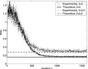
Fig. 5. Convergence curve for MSE. Theoretical values are obtained from (67).
Also, , , and . The DoAs are set
as
(radians). Simulations with 400 independent trials are con-ducted. Figs. 4–6 show the adaptation results for the pro-posed algorithm. Also shown in these figures are the corre-sponding theoretical predictions derived in Sections III and IV. Fig. 4 shows the convergence curves for averaged
Fig. 6. Convergence curve for SINR. Theoretical values are obtained from (71) and (72).
and . Note that the convergence behaviors for , , are all similar. Two delay scenarios with and are considered. As we can see, converges to its optimum values, one for and 0.5 for . By contrast, converges to a small value close to zero. Fig. 5 gives the convergence curves for MSE. As expected, the MSE for is larger than that for . Using (67), we obtain theoretical steady-state MSEs for and as 0.158 and 0.278, respectively. From the figure, it is apparent that the experimental result matches the theoretical one quite well. The corresponding output SINR for the beamformer is shown in Fig. 6. The theoretical SINRs are calculated with (72) and (71), and they are 7.34 and 4.25 dB for and , respectively. As seen, the SINR is in-creased from 12 to 7.34 dB in 700 iterations (for ). The beamformer in the proposed algorithm effectively suppresses the interference.
As mentioned in (37), can be estimated from and . Simulations are carried out to evaluate the perfor-mance of the estimation. We randomly generate and for 500 trials. The MSE, defined as , is used as the performance measure, where denotes an estimate of at
. Here, we let and chips for
filter adaptation. For simplicity, we perform estimation of only
when and are the first two maximums
Fig. 7. MSE for fractional delay estimate in AWGN and multipath channel.
the estimation errors is small. For an SNR (per chip) of 2 dB, the MSE is only 10 . The SNR here is defined as and . Note that in the same figure, the result for a multipath channel, which will be discussed later, is also included.
Next, we will consider the performance of acquisition. Let us first examine the probability of correct acquisition [(85) and (90)]. Fig. 8 gives the simulation results for various step sizes. Here, we let , , and the array input SINR (per chip) be 15 dB. Theoretical values calculated with (85) and (90) are also shown for comparison. It is clear from Fig. 8 that the experimental results highly agree with the theoretical ones. When , the probability of correct acquisition is somewhat lower. This is due to the fact that optimum values of
and are smaller than one. Also, we can see that the experimental probability of correct acquisition is lower than the theoretical one. This indicates that is not sufficiently large and adaptive filters have not reach their steady states. As we will see below, experimental results can be very close to the results calculated with (90) when is large.
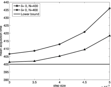
We then substitute the experimental probabilities shown in Fig. 8 into (92) to derive the mean acquisition time. The result is shown in Fig. 9. It is seen that the proposed algorithm can acquire an integer delay in a short period of time. For example, is 402 chips when is 3 10 . The mean acquisition time for fractional delay is slightly larger than that for integer delay. In Fig. 9, is selected somewhat arbitrarily and the value may be not optimal. Fig. 10 shows the mean acquisition time for
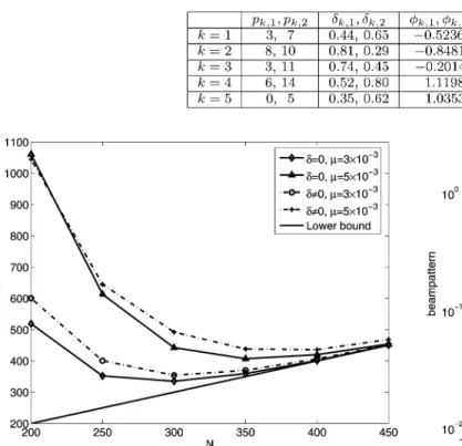
various with and . The lower bound
being serves a performance benchmark. For integer code-delay, when is greater than 350, the mean acquisition time becomes close to the lower bound. Also, we can see that the minimum mean acquisition time is around for
. The acquisition performance for fractional delay will be poorer if is too small. For larger than 400, it becomes close to that in integer delay. The minimum mean acquisition
time is around for .
Fig. 8. Probability of correct acquisition versus step size. Theoretical values are obtained from (85) and (90).
Fig. 9. Experimental mean acquisition time (in chips) versus step size for AWGN channel.
From Fig. 10, we can see that there is an optimum for a given array input SINR. To let the system be operated in its op-timum conditions all the time, we can build a table for opop-timum
s (versus input SINR) offline and then obtain an optimum with a table lookup online. If we assume that the power of the re-ceived signal is dominated by MAI, an estimate of input SINR
can be . We have found that
this SINR estimate can converge fast and provide good results.
B. Multipath Channels
For the scenario of multipath channels, we let the number of channel paths be two for all users. Also, let
and . Other related parameters used in simula-tions are summarized in Table I. This setting leads the antenna array operating in a heavily loaded case (i.e., the number of overall multipaths is greater than that of array sensors). Simu-lations with 500 trials are conducted. Fig. 11 shows some ex-perimental beam patterns derived from and the
theo-TABLE I
PARAMETERSUSED FORSIMULATIONS INMULTIPATHSCENARIO
Fig. 10. Experimental mean acquisition time (in chips) versusN and step size for AWGN channel.
retical beam pattern from Section III-C. Note that the arrow signs indicate the DoAs of all users, and only the DoAs of the desired user are labeled. The beamformer forms two main beams collecting the desired signals coming from the angles 0 and 0.5236 rad. From Fig. 11, we see that some interference cannot be deeply nulled. This is because their incident angles are close to the desire user’s DoAs. The convergence behavior of the MSE and SINR is similar to those shown previously, and the corresponding figures are then omitted. Specifically, we find that the steady-state MSE is 0.35 and output SINR of the beam-former is 1.98 dB. We then examine the performance of frac-tional delay estimation. We randomly generate code-delays for all paths and all users for acquisition and calculate the MSE, defined as . The SNR here is defined as . Fig. 7 gives the result with 500 trials. We can see that the performance is worse than that in AWGN case. Also, it is more sensitive to the SNR. When SNR is low, the per-formance is seriously affected.
C. Performance Comparison
Finally, we compare the proposed scheme with the corre-lator-based scheme described in [14]. Since the scheme in [14] does not consider the case with fractional delay, we let the code-delay be integer. Also, the channel is an AWGN channel. We
assume , , , and .
The setting of DoAs is the same as that in Section VI-A. For the proposed system, we let . Then, we
experimen-Fig. 11. Experimental and theoretical beam patterns for multipath channel. Arrow signs indicate DoAs of all users; the labeled are DoAs of the desired user.
tally search for an optimal set of giving minimal mean acquisition time for each input SINR. For the system in [14],
we let and . Note that [in
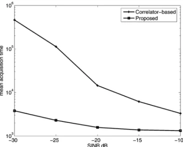
(5)]. As addressed in [14], the convergent filter-weight vector is not exactly identical to the steering vector of the desired user, and there exists a gap between the experimental and theoret-ical performance (for ), especially at low SINR. In other words, the theoretical threshold derived from [14] may not guar-antee . Let , where is a positive scalar. To ensure a fair comparison, we experimentally search for the threshold and step size to achieve the optimum performance. Fig. 12 shows the mean acquisition times versus the array input SINR for the correlator-based and proposed schemes. From the figure, we can see that the proposed system significantly out-performs the correlator-based system, especially for low SINR. For example, when the SINR is 30 dB, the performance gap between the proposed system and the correlator-based system exceeds two orders of magnitude. The poor performance of the correlator-based algorithm stems from the slow convergence of the adaptive filter and its necessity for code-phase searching. The proposed scheme simultaneously performs beamforming and code acquisition, yielding much better performance in in-terference suppression and filter convergence.
VII. CONCLUSION
In this paper, we propose a novel adaptive antenna array for code acquisition. Unlike the correlator-based serial-search
Fig. 12. Mean acquisition time (in chips) comparison.
scheme, the proposed system can simultaneously perform beamforming and code acquisition. Another distinct feature is that the proposed algorithm can deal with both integer and fractional code-delays. For multipath channels, the proposed system can acquire multipath delays and serve as a channel estimator. We also theoretically analyze the properties and performance of the proposed algorithm. Closed-form solutions for optimum solutions, steady-state MSE, and SINR are de-rived. We also show that experimental results highly agree with analytical ones. Simulations results show that the proposed system significantly outperforms the correlator-based one in [14]. In this paper, we consider the scenario of single transmit antenna. However, the proposed algorithm can also be applied to the scenario of multiple transmit antennas. Acquisition in the multiple-input multiple-output system is a potential topic for further research.
REFERENCES
[1] A. Polydoros and C. Weber, “A unified approach to serial search spread-spectrum code acquisition—Part I and II,” IEEE Trans.
Commun., vol. COM-32, pp. 542–560, May 1984.
[2] A. J. Viterbi, Principle of Spread Spectrum Communications. New York: Addison-Wesley, 1995.
[3] J. K. Holmes, Coherent Spread Spectrum Systems. New York: Wiley, 1982.
[4] U. Madhow and M. B. Pursley, “Acquisition in direct-sequence spread-spectrum communication networks: An asymptotic analysis,”
IEEE Trans. Inf. Theory, vol. 39, pp. 903–912, May 1993.
[5] T. K. Moon, R. T. Short, and C. K. Rushforth, “Average acquisition time for SSMA channels,” in Proc. IEEE Military Commun. Conf., 1991, pp. 1042–1046.
[6] D. Zheng, J. Li, S. L. Miller, and E. G. Ström, “An efficient code-timing estimator for DS-CDMA signals,” IEEE Trans. Signal Process., vol. 45, pp. 82–89, Jan. 1997.
[7] E. G. Ström, S. Parkvall, S. L. Miller, and B. E. Ottersten, “Propaga-tion delay estima“Propaga-tion in asynchronous direct-sequence code-sequence multiple access systems,” IEEE Trans. Commun., vol. 44, pp. 84–93, Jan. 1996.
[8] M. G. El-Tarhuni and A. U. Sheikh, “An adaptive filtering PN code acquisiion scheme with improved acquisition based capacity in DS/CDMA,” in Proc. 9th IEEE Int. Symp. Personal, Indoor, Mobile
Radio Commun., 1998, vol. 3, pp. 1486–1490.
[9] M. G. El-Tarhuni and A. U. Sheikh, “Adaptive synchronization for spread spectrum systems,” in IEEE Veh. Technol. Conf., Apr. 1996, vol. 1, pp. 170–174.
[10] M. G. El-Tarhuni and A. U. Sheikh, “Code acquisition of DS/SS signals in fading channels using an LMS adaptive filter,” IEEE Commun. Lett., vol. 2, pp. 85–88, Apr. 1998.
[11] R. F. Smith and S. L. Miller, “Acquisition performance of an adap-tive receiver for DS-CDMA,” IEEE Trans. Commun., vol. 47, pp. 1416–1424, Sep. 1999.
[12] H. L. Yang and W. R. Wu, “Multirate adaptive filtering for DS/CDMA code acquisition,” in IEEE Int. Symp. Signal Process. Inform. Technol., Dec. 2003, pp. 363–366.
[13] Y. Zhang, L. Zhang, and G. Liao, “PN code acquisition and beam-forming weight acquisition for DS-CDMA systems with adaptive array,” in Proc. 14th IEEE Int. Symp. Personal, Indoor, Mobile Radio
Commun., 2003, vol. 2, pp. 1385–1389.
[14] B. Wang and H. M. Kwon, “PN code acquisition using smart antenna for spread-spectrum wireless communications—Part I,” IEEE Trans.
Veh. Technol., vol. 52, pp. 142–149, Jan. 2003.
[15] B. Wang and H. M. Kwon, “PN code acquisition using smart antenna for spread-spectrum wireless communications—Part II,” IEEE Trans.
Wireless Commun., vol. 2, pp. 108–117, Jan. 2003.
[16] H. L. Yang and W. R. Wu, “A novel adaptive code acquisition using antenna array for DS/CDMA systems,” in Proc. IEEE Int. Workshop
Antenna Technol.: Small Antennas Novel Metamater., Mar. 2005, pp.
458–461.
[17] M. D. Katz, J. Iinatti, and S. Glisic, “Two-dimentional code acquisition in time and angular domains,” IEEE J. Sel. Areas Commun., vol. 19, pp. 2441–2451, Dec. 2001.
[18] M. D. Katz, J. Iinatti, and S. Glisic, “Two-dimentional code acquisition in environments with a spatially nonuniform distribution of interfer-ence: Algorithms and performance,” IEEE Trans. Wireless Commun., vol. 3, pp. 1–7, Jan. 2004.
[19] S. Buzzi and H. V. Poor, “On parameter estimation in long-code DS/CDMA systems: Cramér–Rao bounds and least-squares algo-rithms,” IEEE Trans. Signal Process., vol. 51, no. 2, pp. 545–559, Feb. 2003.
[20] C. Sengupta, J. R. Cavallaro, and B. Aazhang, “On multipath channel estimation for CDMA systems using multiple sensors,” IEEE Trans.
Commun., vol. 49, pp. 543–553, Jun. 2001.
[21] S. Affes and P. Mermelstein, “A new receiver structure for asyn-chronous CDMA: STAR—The spatial-temporal array-receiver,” IEEE
J. Sel. Areas Commun., vol. 16, pp. 1411–1421, Oct. 1998.
[22] J. Ramos, M. D. Zoltowski, and H. Liu, “Low-complexity space-time processor for DS-CDMA communications,” IEEE Trans. Signal
Process., vol. 48, no. 1, pp. 39–52, Jan. 2000.
[23] Z. Liu, J. Li, and S. L. Miller, “An efficient code-timing estimator for receiver diversity DS-CDMA systems,” IEEE Trans. Commun., vol. 46, pp. 826–835, Jun. 1998.
[24] G. Seco et al., “Exploiting antenna arrays for synchronization,” in
Signal Processing Advances in Wireless and Mobile Communications,
G. B. Giannakis, Ed. et al. Upper Saddle River, NJ: Prentice-Hall, 2001, vol. 2.
[25] O. S. Shin and K. B. Lee, “Utilization of multipath for spread-spec-trum code acqusiition in frequency-selective Rayleigh fading chan-nels,” IEEE Trans. Commun., vol. 49, pp. 734–743, Apr. 2001. [26] H. W. Je, O.-S. Shin, and K. B. Lee, “Acquisition of DS/CDMA
sys-tems with multiple antennas in frequency-selective fading channels,”
IEEE Trans. Wireless Commun., vol. 2, pp. 787–798, Jul. 2003.
[27] Mobile station-base station compatibility standard for dual-mode
wideband spread spectrum cellular system, TIA/EIA/IS95, Telecommun. Industry Assoc., 1993.
[28] E. H. Diana, B. Jabbari, and G. Mason, “Spreading codes for direct sequence CDMA and wideband CDMA cellular networks,” IEEE
Commun. Mag., vol. 36, pp. 48–54, Sep. 1998.
[29] S. Haykin, Adaptive Filter Theory, 3rd ed. Englewood Cliffs, NJ: Prentice-Hall, 1996.
[30] N. J. Bershad and L. Z. Qu, “On the probability density function of the LMS adaptive filter weights,” IEEE Trans. Acoust., Speech, Signal
Process., vol. 37, pp. 43–56, Jan. 1989.
[31] J. G. Proakis, Digital Communications, 4th ed. New York: McGraw-Hill, 2000.
[32] H.-R. Park and B.-J. Kang, “On the performance of a maximum-like-lihood code-acquisition technique for preamble search in a CDMA re-verse link,” IEEE Trans. Veh. Technol., vol. 47, pp. 64–74, Feb. 1998.
Hua-Lung Yang was born in Taipei, Taiwan, R.O.C.,
in 1977. He received the B.S.E.E. degree from Feng Chia University, Taichung, Taiwan, in 1999 and the M.S.E.E degree from National Taiwan University of Science and Technology in 2001. He is currently pur-suing the Ph.D. degree at National Chiao Tung Uni-versity, Hsinchu, Taiwan.
His main research interests include spread-spec-trum techniques, synchronization, antenna array sys-tems, and statistical signal processing.
Wen-Rong Wu was born in Taiwan, R.O.C., in
1958. He received the B.S. degree in mechanical engineering from Tatung Institute of Technology, Taiwan, in 1980. He received the M.S. degree in mechanical engineering and in electrical engineering and the Ph.D. degree in electrical engineering from the State University of New York at Buffalo in 1985, 1986, and 1989, respectively.
Since August 1989, he has been a Faculty Member with the Department of Communication Engineering, National Chiao Tung University, Taiwan. His research interests include statistical signal processing and digital communications.