A method for measuring the rotatory power of a chiral medium
Der-Chin Su *a
Chen-ChihHsu a,Jiun-You
Lin a andJu-Yi Lee *b
a
Institute
of Electro-Optical Engineering, National Chiao Tung University, 1001 Ta-Hsueh Road,
Hsin-Chu, Taiwan, R.O.C.
b Center for Measurement
Standars, Industrial Technology Research Institute, Bldg. 16, 321 Kuang
Fu Road, Sec 2, Hsin-Chu, Taiwan, R.O.C.
ABSTRACT
A light beam coming from a circularly polarized heterodyne light source passes through a chiral medium, its rotation angle is just half of the phase difference between p- and s- polarization components. And this phase difference can be measured accurately with heterodyne interferometric technique. The rotatory power is obtained by dividing
the estimated rotation angle with its path length. This method has many advantages, such as, high stability, high
resolution, easy operation, and real-time measurement.
Keywords: chiral medium, rotatory power, optical rotation angle, heterodyne interferometry.
1. INTRODUCTION
Rotatory power or specific rotation is an important characteristic constant of a chiral medium[1]. Although there are some techniques that have been proposed for measuring rotatory power, almost all of them are related to the light intensity variations[2-4]. However, the stability of light source, the scattering light, the internal reflection, and other
factors influence the accuracy of measurements and decrease the resolution of results. In order to overcome these
drawbacks, some improved methods using heterodyne interferometry are proposed[5-8]. Their heterodyne light sources are achieved by either introducing an acoustic-optic modulator to each arm of Mach-Zehnder interferometer or rotating polarization optical elements. Owing to their uncommon path configurations or the mechanical vibration, they are easily influenced by the surrounding vibration and air turbulence.
Further author
information-*
D.C.S.(correspondence): Email: [email protected]; Telephone: 886-3-5731951; Fax: 886-3-5716631
*
In this paper, an improved method for measuring the rotatory power of a chiral medium is presented. A
circularly polarized heterodyne light source consisting of a linearly polarized laser source, an electro-optic modulator driven by a voltage signal generator, and a quarter-wave plate is used. The light beam coming from this light source passes through the tested chiral medium, its phase difference between p- and s- polarization components is twice of the rotation angle. And it can be measured accurately with heterodyne interferometric technique. Then, the rotatory power can be estimated by dividing the estimated rotation angle with the concentration and the the path length of the tested
chiral solution[9]. Because of its common-path heterodyne interferometric configuration, this method has many
advantages, such as, high stability, easy operation, and real-time measurement. And its feasibility is demonstrated and it has 0.015 degree resolution
2. PRINCIPLE
Circularly polarized
heterodyne light source
__
Fig.1: Schematic diagram for measuring the phase difference. EO: electro-optic modulator; FG: function generator; Q: quarter-wave plate; BS: beam splitter; CM: chiral medium; AN: analyzer; D: photodetector; PM: phasemeter.
The schematic diagram of this method is shown in Fig. 1. For convenience, the +z axis is chosen along the
propagation direction and the y-axis is along the vertical direction. If the light beam coming from a laser source is linearly polarized at 45°withrespective to the x-axis, then its Jones vector can be written as
E ==(J,
(1)And it passes through an electro-optic modulator EO and a quarter-wave plate Q with the fast axis being at 45° with
respective to the x-axis. If the fast axis of EO is along the x-axis, and an external sawtooth voltage signal from a
function generator FG with angular frequency wandamplitude V,2, the half-wave voltage of EO, is applied to EO, then the retardation produced by EO can be expressed as cot,andthe Jones vector of the light can be written as
E' =
Q(45)EO(ot)E
1(1 i")e2
0
1(1
7\i
11)0 e2
71
1(1"\ .O)t
1"
•wt.it= —f-I Ie'T +
1e22
. (2)2Li)
2L—i)
From Eq.(2), it is obvious that left- and right-circular polarizations have an angular frequency difference w. The
complete set-up for performing the operation Eq. (2) consists of a laser, an electro-optic modulator EO which is driven
by a function generator FG and a quarter-wave plate Q. This set-up acts as a circularly polarized heterodyne light
source. Then, the light is incident on the beam-splitter BS and is divided into two parts by BS : the reflected light and the transmitted light. The reflected light passes through an analyzer ANr with the transmission axis being at 45° with respective to the x-axis and enters into a photodetector Dr. Consequently, the Jones vector of the light becomes
Er=ANr(45°) E'
• (Ot — 1(1l')l(l
i') e'j
0l(1
—2l
i)jTi i)
0 e_.2! iT'
2 1.
= _(l+l)cos(__)J
(3) Hence the intensity measured by Dr isHere, 'r
Sthe reference signal. On the other hand, the transmitted light enters the solution of a chiral mediumcontained in a cylindrical glass tube. Then, it passes through an analyzer ANt with the transmission axis being at 45° with respective to the x-axis and is detected by another photodetector Dt. And the Jones vector ofthe light becomes
Et=ANt(45°)CM(O
) E'—
ill
1( cosO sinO") 1 (1i"1 e' 0
1 (1—
21
1A—sin9 cosO)
i)
e2
1 (Dt
= _(1+i)cos(_+9)1)
, (5)whereCM(G) is the Jones matrices of the chiral medium[6I and 9 is the optical rotation angle. Therefore, the intensity
measured by Dt is
1=IEt
2=i[1+cos(wt+26)]
.
(6)Here, I is the test signal. From Eq.(4) and Eq.(6), it is obvious that both the reference signal and the test signal are
sinusoidal with angular frequency co.Thesetwo sinusoidal signals are sent to the phase meter PM as shown in Fig. 1. The phase difference between the reference signal and test signal
çb=20
, (7)can be obtained. From Eq. (7), it is seen that the phase difference q5 is just twice of the rotation angle 9 .From the relation O=q5/2,the rotation angle 9 can beestimated.Finally, the rotatory power or the specific rotation
T
0
[a]Ph
=
CL
(8)can be calculated under the measurements of the rotation angle 9, the concentration C of the solution of the chiral medium, and the path length L of the cylindrical glass tube. [a]Phisexpressed in degree/(dm gil) or degreel(dm
glg)[9I. C and L are expressed in gil or gig and decimeters (dm), respectively. The symbols ?, pH and T means that the rotatory power a depends on the wavelength X, pH and the temperature of the solution of the chiral medium.
3. EXPERIMENTS AND RESULTS
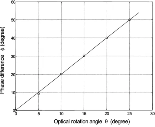
A He-Ne laser with a 632.8 nm wavelength and an electro-optic modulator (Model PC200/2, manufactured by England Electro-Optics Developments Ltd.) with a half-wave voltage of 170 V were used[1O]. The frequency of the sawtooth signal applied to the electro-optic modulator was 2kHz. At first, to show the validity of this technique, a half-wave plate was introduced to replace the solution of the chiral medium. Fig. 2 shows the relation curve of the measured
phase difference q5 versus the optical rotation angle 0 introducedby the half-wave plate. This relation curve is a
straight line with a slope of 2. Hence, it is clear that our derivation shows good validity.
0) a)
0
-e-a) (I) Co-0
Fig. 2 : The relation curve of the phase difference versus the optical rotation angle 0fora half-wave plate.
Secondly, several sucrose solutions with different concentrations were measured. A cylindrical glass tube with a 2 decimeter length and 20 ml volume was used to contain the sucrose solution. The theoretical and experimental curves
of the rotation angle 0 versus the concentration C (in g/lOOg) are shown in Fig. 3. In this figure, the solid curve
represent the theoretical values which are obtained by introducing the reference rotatory power[9] into Eq. (8). It is
10 15 20 25
clear that this curve shows good correspondence except at high concentration. From the experimental results, the
rotatory power of the sucrose solution is 56.25(g/lOOg )
(dm)at 632.8nm and the reference value is
56.51(g/lOOg)1 (dm)1 at 636.2 nm.[9] ci
2
a) C)0
Fig. 3 .Thetheorectical and experimental curves of the optical rotation angle 8 versusthe concentration C for sucrose solution.
4. DISCUSSION
Because a circularly polarized heterodyne light source is used in this method, the intensities of the signals are
independent on the azimuth angles of the transmission axes of analyzers. But, when the transmission axis of the
analyzer fixed at 45 ,thephase difference error coming from the extinction ratio of analyzer will be minimum. The
resolution depends on the resolution of the phasemeter and the optical configuration. From Eq. (7), we can estimate the error in optical rotation angle 0. Itcan be written as
L,/Y
°
:
°
I Co 5 10 15 20 25Concentration
C (gil OOg)2
(9)
where
A9
isthe error in the phase difference. Angular resolution, second harmonic errors and polarization-mixingerror may influence the errors in the phase difference in this method[1O]. So the total phase difference error can
decrease to 0.03° inour experiments. Substituting this data into Eq. (9), we have 0.015
Eq. (8) is valid only for the chiral liquid and the solution of the chiral medium. As for a crystal, this method is still valid. But the rotatory power is defined as the measured rotation angle divided by its thickness (in mm unit).
This method is not related to the measurement of light intensity variations, it is free from the stability of a light source. In addition, because of its common-path interferometric structure, it is very stable and has a high resolution.
5.CONCLUSION
A light beam coming from a circularly polarized heterodyne light source passes through a chiral medium, its rotation angle is just half of the phase difference between p- and s- polarization components. And this phase difference can be measured accurately with heterodyne interferometric technique. Based on these facts, an improved method for measuring the rotatory power of a chiral medium is presented in this paper. It is very stable and has a high resolution. And its feasibility is demonstrated and its resolution is 0.015 degree.
ACKNOWLEDGMENTS
This study was supported in part by the National Science Council, Taiwan, under contract N5C89-2215-E009-083.
REFERENCES
1. A. Yariv and P. Yeh, "Optical Waves in Crystals", Jone Wiley and Sons, Inc., Chap.4, p.p.69-l2O, 1984.
2. M. J. Goetz, Jr. "Microdegree Polarimetry for Glucose Detection", MS Thesis, University of Connecticut, Storrs, CT, 1992.
3. W. March, R. Engerman, and B. Rabinovitch, "Optical monitor of glucose ",ASAIOTrans. 25,p.p.28-3l, 1979. 4. T. W. King, G. L. Cote, R. McNichols and M. J. Goetz, Jr., "Multispectral Polarimetric Glucose Detection Using
a Single Pockels Cell", Opt. Eng., 33, p.p.2746-2753, 1994.
5. C.Chou, Y. C. Huang, C. M. Feng and M. Chang, "Amplitude Sensitive Optical Heterodyne And Phase Lock-in Technique on Small Optical Rotation Angle Detection of Chiral Liquid", Jpn. J. App!. Phys. 36, p.p.356-359, 1997.
6. H. J. King, C. Chou, H. Chang and Y. C. Huang, "Concentration Measurements in Chiral Media Using Optical Heterodyne Polarimeter", Opt. Commun. 110, p.p.259-262, 1994.
7. T. Mitsui and K. Sakurai, "Precise Measurement of The Refractive Index and Optical Rotatory Power of A
Suspension by a Delayed Optical Heterodyne Technique", Appl. Opt. 35, p.p.2253-2258, 1996.
8. G. L. Cote, M. D. Fox and R. B. Northrop, "Noninvasive Optical Polarimetric Glucose Sensing Using a True Phase Measurement Technique", IEEE Tran. Biomed. Eng. 39, p.p.752-756, 1992.
9. CRC, "Handbook of Chemistry and Physics", 63rd edition, p.p.E-405, 1982.
10. M. H. Chiu, J. Y. Lee and D. C. Su, "Refractive index measurement based on the effects of the total internal