14 IEEE TRANSACTIONS ON AUTOMATION SCIENCE AND ENGINEERING, VOL. 1, NO. 1, JULY 2004
Development of an Intelligent Energy Management
Network for Building Automation
Hsiao-Yi Huang, Jia-Yush Yen, Member, IEEE, Sih-Li Chen, and Feng-Chu Ou
Abstract—This paper describes the development of an intelli-gent energy management network (IEMN) using the concept of a surrogate object-communication model and three-layered network architecture. The proposed IEMN is characterized by its network architecture and application services. From the network architec-ture point of view, the IEMN is characterized by the area control and management center, the building control and management sta-tion, and the BACnet facility. From the application service point of view, the IEMN provides the intelligent energy service architecture to integrate the building management system functions and the fa-cility management system. The IEMN offers several advantages such as the distributed intelligent management and the ability of data processing and analysis online. The hierarchical architecture makes it easy to integrate and to expand.
Note to Practitioners—The paper describes an extension to the existing intelligent build network technology. The conventional telligent building network facilitates the monitoring of sensor in-formation and the issuing of controller commands by assuming that the network elements all have limited intelligence. The con-trol decision is therefore centralized to some concon-trol servers. The proposed surrogate system, on the other hand, allows for intelli-gent control subunits on the network and transmits more complex information and directions for control decision making. The con-trol subunit will have the freedom to make their own decision on how to achieve the instructions from the upper level. Thus, the net-work traffic may be reduced and the netnet-work no longer has to deal with time critical issues. This configuration allows more room for network flexibilities. We have constructed the basic network with SQL and active server page and run a primitive demonstration in our laboratory. Because the setup is configured over a standard BACnet facility over TCP/IP, the network implementation does not require too much effort. The layered network servers are still necessary.
Index Terms—BACnet protocol, building automation, surrogate object.
I. INTRODUCTION
T
HE BUILDING automation system (BAS) had gained a great amount of attention in recent years. Many research results have been developed. While the earlier systems use cen-tralized control with pneumatic actuators, the newer version of BAS has moved toward distributed control with direct digital equipments. More recently, the building automation system has Manuscript received February 27, 2003. This work was supported by the National Science Council under Contract NSC90-2212-E-002-219.H.-Y. Huang, J.-Y. Yen, and S.-L. Chen are with the Department of Me-chanical Engineering, Tjing-Ling Industrial Research Institute, National Taiwan University, Taipei 10617, Taiwan, R.O.C. (e-mail: [email protected]).
F.-C. Ou is with the Department of Mechanical Engineering, K.W. Institute of Technology, Taipei, Taiwan, R.O.C.
Digital Object Identifier 10.1109/TASE.2004.829346
started to work with the network and the artificial intelligent technology, where a hierarchical distributed database was often used to monitor and detect facility malfunctioning [1]–[4].
Building automation composes a large industry; there are many commercial network standards already in use. Because air-conditioning related processes are relatively slow, the most popular networks all stress on the number of vendors who support the standard. Among the most popular standards, CEbus operates at 10 Kbps, LONworks operates at 1.25 Mbps, Smart House operates at 50 Kbps, presently. LONworks and Smart House offer custom integrated circuits (ICs) for implementation. CEbus, on the other hand, can be implemented with simple 8-bit microprocessors. CEbus and LONwork also support implementation over the power line, which is a desir-able feature for home usage. In 1995, the American Society of Heating Refrigeration and Air-condition Engineers (ASHRAE) published the BACnet protocol as a data communication protocol for building automation and control networks. The protocol was later approved by International Organization for Standardization as ISO standard 16 484-5 in January 2003. The BACnet protocol stresses an open protocol and it is gaining increased attention in the HVAC community. Theoretically, BACnet allows for the integration of different protocols from different vendors [5]–[7], but the actual implementation may still require special purpose gateways. The data on building management systems (BMS) can then be routed through some IP routers, and remote monitoring and control can then become possible. To remedy this difficulty, this paper proposes to introduce the surrogate object in [8] to the energy management network. The surrogate object simplifies the communication process and improves the network efficiency. As for building automation networks, people first start to use the modular networked computers to accommodate the uncertain needs of the energy industry in the late 1990’s [9]. During the period, Clark and Mehta also introduced artificial intelligence into the building management network (BMN) [10]. Ma fet al. utilized the intranet/internet, relational database, and object-oriented technologies to design the infrastructure for a knowledge-based artificial intelligence system for BMS [11]. More recently, people start to notice the convenience of the web technology and have investigated the use of web technology with the BMN [12], and have started to look into interconnecting BMS local networks via the Internet/intranet and exchange information with the facility management system (FMS) [13]. Newer efforts have also started to look into a web-based software system to support electronic commerce for deregulating power markets [14].
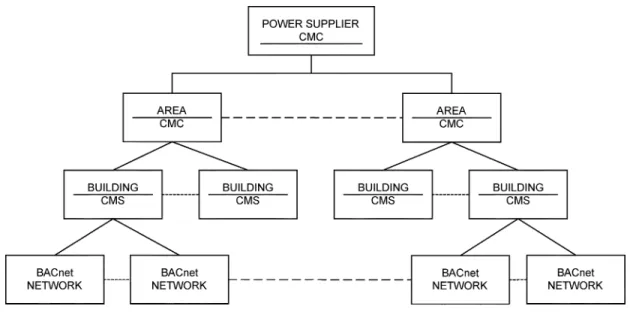
Fig. 1. Service management hierarchy of IEMN.
With all the advances, little effort has been made to deve-lope an intelligent network management system that includes facility management functions and the ability to integrate with the BMS for energy management. There is also a lack of effi-cient intelligent service architecture for remote monitoring and control. In this paper, a BACnet-based intelligent energy man-agement network (IEMN) using a surrogate object-communi-cation model is proposed. The facilities in the buildings around the neighboring area are linked via the network. An intelligent management structure is developed to coordinate the network databases and application programs and to carry out the auto-matic decision making and remote monitoring functions. The IEMN management hierarchy includes: the area control and management center (ACMC), the building control and man-agement station (BCMS), and the BACnet facility. There is a three-layered distributed processing architecture for monitoring and control, called the intelligent energy service architecture. The layers are the facility management layer, the BCMS con-trol and monitoring layer, and the ACMC concon-trol and manage-ment layer. The intelligent energy service architecture serves to integrate the FMS and the BMS functions and to carry out data treatment in the network.
The IEMN comprises features such as: a distributed intel-ligent process, a hierarchical system for security, and the ca-pacity for integration and expansion. The purpose of the IEMN is to provide real-time information and online services for users and power companies. The data process and intelligent decision making can also serve as an infrastructure for a power-trading platform.
II. SYSTEMARCHITECTURE
The system architecture of the proposed IEMN is based on the BACnet protocol to integrate the Internet and the intranet. The architecture design allows the implementation of an
en-ergy network monitoring and controlling system, and provides an infrastructure model for the open market in electrical power. In the network management hierarchy, the IEMN includes the ACMC, the BCMS, and the BACnet. Fig. 1 shows the service management hierarchy. All control units of the energy man-agement system, such as the HVAC systems, the lighting con-trol systems, the fire alarm and sprinkler systems, the security system, the elevator control systems, the intrusion alert system, etc., are connected by the BACnet protocol. These BACnet fa-cilities are then monitored by the settings of the BCMS. The connection with a specific number of buildings through the in-tranet can form a local area network and can be managed by the ACMC. The ACMC is then connected with the power com-panies through Internet. The power comcom-panies can obtain the information for the local power requirement and usage from the ACMC. The power supplier is the contracted power company. In the future, there can be other power companies, namely inde-pendent system operators (ISOs). In addition, the administrator of the system may implement remote control and management through the network.
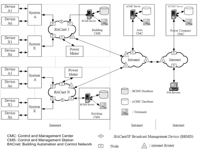
The system architecture of the IEMN is illustrated in Fig. 2. Devices interconnect each other through the BACnet. Each BACnet loop connects with the intranet through some BACnet router. The intranet can then interconnect with the Internet. Therefore, the system inherently favors the use of different protocols in the different layers. The multiprotocol structure also enhances network security. As an example, a network can be composed of the TCP/IP for the Internet, the NetBEUI or IPX for the intranet, and the BACnet protocol for the BACnet facility. The function of each participant is described next.
1) BACnet: The BACnet connects the bottom layer of every
building’s system device with the control unit. Through the BACnet network, the devices interconnect with the intranet. The BACnet is inherently a distributed network that makes the system comparable and expandable.
16 IEEE TRANSACTIONS ON AUTOMATION SCIENCE AND ENGINEERING, VOL. 1, NO. 1, JULY 2004
Fig. 2. System architecture of IEMN.
2) Building Control and Management Station: The BCMS
is used to manage and control the network from the building level. It controls and monitors every system of the building, in-cluding the servers and the databases. The energy requirement and energy consumption from each system is transferred to the control and management center and is used to update the ACMC database. If there is any abnormal alarm from the system, BCMS can respond to the ACMC immediately.
3) Area Control and Management Center: The ACMC
manages the servers, the databases, and the decision support system (DSS). It reaches the elements of each system through the intranet and the BACnet to search and update the data. A remote user can use this system through Internet connection. The function of the ACMC comprises of network management and energy service management. The network management section deals with the system configuration, fault handling, system performance, accounting, and security. Energy service management will be introduced in more detail in Section V.
4) Remote User: The remote user includes the electric
power companies and the other authorized users. The electric power supplier can be a power company or an ISO, which is connected to ACMC servers through the intranet to retrieve data and to remotely control the system.
III. BACNETNETWORKCOMMUNICATION ANDDATASHARING
A. Objects and Services on BACnet
The advancement of microprocessor technology has pushed the control technology toward distributed control. The local
con-troller only handles a single device, such as a variable air volume device, etc. These local controllers each constitutes a node in the BACnet, and are capable of limited calculation. The integrated network architecture allows for the system to inherit the com-putation power from the BCMS or the ACMC. The distributed object has to be integrated with a very efficient distributed ob-ject-communication system, so that a simple object can be in-tegrated into a complex building automation application. The surrogate object suggested in [8] combines with the BACnet protocol then forms a powerful IEMN communication model to allow both flexibility and expandability.
1) Object and Attribute: In the BACnet protocol, the objects
are defined as the corresponding devices. Each object contains a lot of information, which is adapted to describe the property of each object and its status. For example, a temperature measure-ment device includes the information of device name, device lo-cation, and measurement data, which are called the “attributes” of the object. The BACnet protocol defines 18 standard objects. Each of these owns different functions and various attributes [6]. Every device owns different objects according to different func-tions. Each object attribute comprises three used ways: optional, readable, and writeable. Properly configured BACnet devices will have these attributes defined. Users can then communicate with these devices through the BACnet. In addition, users can also define an object according to individual needs, such as ob-ject identifier, obob-ject name, and obob-ject type.
2) Services: The BACnet protocol uses the “service” to
carry out the communication and control between the objects. The service has the function of obtaining data from other
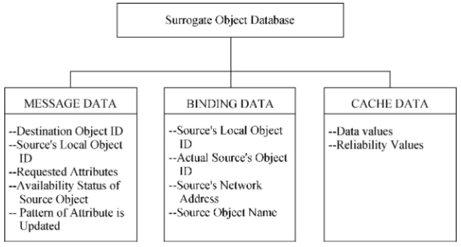
Fig. 3. Surrogate object database.
devices, commanding other devices for actuation, and an-nouncing the same events happened in one or more devices. The application program issues and receives service request. After the application program issues the service request to other device’s object, it obtains the requested data from the reply of the object. Service messages via network can be encoded in the BACnet protocol devices when the devices are installed [5]. The services in the BACnet protocol comprise six groups: alarm and event services, object access services, file access services, remote device management, virtual terminal services, and security services. Object access services and remote device management are the services most used in this paper.
3) Object Access Services: Object access services comprise
nine application services to provide ways to read or write the properties of objects and to create or delete the objects [5], [6]. The properties of BACnet objects can be stored without con-sidering individual object function. The “create object” service can create a new instance object, which can be used in stan-dard or vendor-specific objects. Object access services also pro-vide the “delete object” service to illuminate the current object. The communications between devices are simplified by using “create object” and “delete object” services to serve a new spe-cific communication object.
4) Remote Device Management: Remote device
manage-ment provides a tool for maintenance and troubleshooting by dynamically locating peer devices [5], [6]. The “who-is” service request is used to locate the current given the device ID address, and to build a local table for the active devices in the BACnet. When a BACnet device needs to know the address of another device, a “who-is” service will be broadcasted to specify an instance number or a specific range status in the intranet. The “I-am” service request responds to the “who-is” service request. Similarly, the “who-has”–“I-have” service owns the functions of the“who-is”–“I-am” service in different device objects.
B. Surrogate Object-Communication Model (I)—Communication Objects
1) Communication Object Classification: The BACnet
de-vice is regarded as a combination of different objects based on different functions because devices consist of objects in the
BACnet protocol. In this paper, the BACnet device is defined as a destination device that issues or communicates requests and the source device implements the request or replies to the re-quest. There are three standard objects related to communication in the source device: the analog input/digital input (AI/DI) ob-ject, the device obob-ject, and the source object. The AI/DI object is used to input the analog/digital information and communicate with the control element.
Every BACnet device owns a device object for providing the device information, and making the device effective in the net-work, that is, it can be requested by other elements. The specific device information’s comprises such as: vendor name, model name, location, protocol version supported, and object-types supported etc. When BACnet controls the related information, it must obtain the device data by the device objects. The func-tion of source object includes reading, writing, or changing the basic attributes of the devices. Reading and writing of the at-tributes are basic actions, but changing of the atat-tributes needs to give commands. Due to the different function of the device, the destination device has different objects. For example, an air-conditioning system owns the function of control, which needs a control object. If the system uses the proportional inte-gral derivative (PID) controller, the control object is called the PID control object and the requested object is called the desti-nation object.
2) Surrogate Object: Recent development in programming
has lead to the concept of the distributed component object model (DCOM) and the surrogate (proxy) model. The surrogate model allows a surrogate object to establish flexible commu-nication between two objects. Even though not exactly the same, the objects and services defined in the BACnet protocol are similar to the objects and services in DCOM or common object request broker architecture (CORBA). A BACnet object includes identity, state, and behavior. A BACnet service is the function for supporting object usage and object implementation services and access objects, produce objects, and maintain the states of an object. It is then convenient to create surrogate objects via the BACnet services to simplify the communication process between the BACnet objects.
The surrogate object is used to confirm the asynchronous connection between devices. The connection of the surrogate objects is generated during the run time. It is created when an
18 IEEE TRANSACTIONS ON AUTOMATION SCIENCE AND ENGINEERING, VOL. 1, NO. 1, JULY 2004
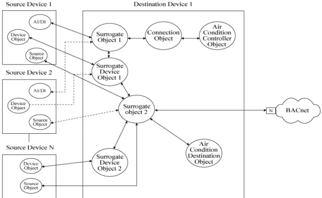
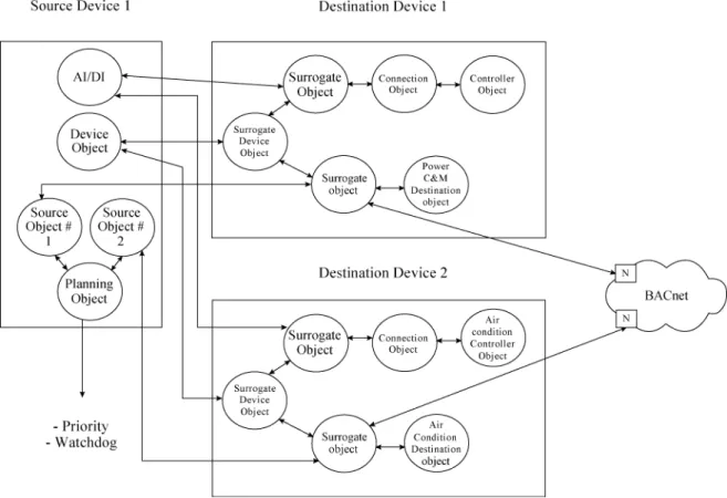
Fig. 4. Surrogate object-communication process (I).
object of the destination device connects with other objects of different devices. When a control object connects with a sur-rogate object, a specific object (namely the connection object) manages and passes the information from the surrogate object to the control object. Unlike the surrogate object, the connec-tion object is created during connecconnec-tion time instead of the run time [8].
The surrogate object is a superclass object. Its structure has the feature of self-descriptive data, which are called metadata. The communications between devices are accomplished by the communication mechanism of metadata in devices. Fig. 3 shows the architecture of the surrogate object database, which includes message data, binding data, and cache data. When the desti-nation device opens the connections with the elements of the other device, the surrogate object will be created. It broadcasts the “who-has” information to find a remote source object in BACnet, and the found source object replies with the “I-have” information to respond to the surrogate object. Then, the surro-gate object creates a message data structure, which comprises the destination object ID, source’s local object ID, requested at-tributes, available status of source object, and updated pattern of the attribute. When the surrogate object is connected with the source object, the surrogate object transfers the message to update its binding data structure including the source’s local ob-ject ID, actual source’s obob-ject ID, source’s network address, and source object name. Thus, the data will be stored into cache data structure, which contains data values and reliability values. All values will be sent to the destination object.
The surrogate device object is used to provide information about the address and operation status of the remote device and to connect the device object for the device status. There is a sur-rogate device object when any remote device owning a source object corresponds to a specific device. The surrogate device
ob-ject is charged to connect with the device obob-ject for transferring the device status.
3) Usage of Surrogate Object: Using the service of the
BACnet protocol provides the function of creating, deleting, or reading the surrogate object message. The “create object” service and “delete object” service can be used to create and delete the surrogate object. And the “who-is”–“I-am” service and the “who-has”–“I-have” service in the remote device man-agement are used to search the source object for the surrogate object [5], [6].
C. Surrogate Object-Communication Model (II)—Communication Process
Surrogate object-communication model in BACnet can be ac-complished from the following basic communication model.
1) Device Search and Monitoring Model: The device search
and monitoring model is used to maintain normal communica-tion in the BACnet. The surrogate device object is used to re-ceive the network address information of the remote device and to inform about the status information of the remote devices. As shown in Fig. 4, the device object of the source device peri-odically provides the address and operation status to the desti-nation device. Simultaneously, the surrogate device object will be created to provide the related information to the surrogate object. The surrogate object uses the network address provided by the surrogate device object and stores the network address in the binding data structure provided by the surrogate device. It uses the available message provided by the surrogate device to update the data in the message data structure. If the surro-gate object of the destination device cannot receive any update or available information from the source device, it will come to the device search model for another source device to keep the network in normal operation.
Fig. 5. Surrogate object-communication process (II).
2) Remote Data Transfer Model and Device Search Model:
The remote data transport model is used to send the data of a specific source object to the requested destination object. The source device could be a temperature sensor, and the destination device could be a temperature argument controller of the air-conditioning control device.
The data transfer model in Fig. 4 has two types: the AI/DI object data transfer model and the source object data transfer model. The AI/DI object is used to input the source device mea-surement data for the destination device. The process of the AI/DI object data transfer is as follows. The air-conditioning control object of destination device creates Surrogate Object 1 through the connection object. Then, Surrogate Object 1 trans-fers the AI/DI object data through a given address of Source Device 1. The data are transferred to the Surrogate Device Ob-ject 1 and the update information is sent to Surrogate ObOb-ject 2 through Surrogate Device Object 1. Surrogate Object 2 records and determines the information and reliability of the source ob-ject. Therefore, it decreases the frequency of data transmission and the load of the network.
The source object data transfer model is used to create Sur-rogate Device 2 directly from the destination object of a desti-nation device (such as the air condition destidesti-nation object) and to transfer the data by a given address of source device. When any failure occurs in the source object, the device object, or the AI/DI object of the source device from a given address, or if the destination device does not know the source device address, the device search model can be applied. Surrogate Object 1 of the destination device broadcasts the“who-has” or “who-is” service in the network to request for source device 2. Source Device 2
will send the “I-have” or “I-am” message to Surrogate Object 1. Then, Surrogate Object 1 transfers data to Surrogate Device Ob-ject 1. Surrogate Device ObOb-ject 1 sends the data and updates the information of the source device. Surrogate Object 2 records and determines the information and reliability. As shown in Fig. 4, the dotted line represents the device search model connection.
3) Schedule Model: Fig. 5 shows the process of a different
destination device to request or command the same source device. The function of the source device, destination device, and device object are the same as the above description. However, when reading, writing, or updating a source object’s attribute, it must be scheduled. Then, the source object will create a planning object to determine the priority and to monitor the watchdog. The BACnet basic operation of monitoring, transferring, and commanding can be done by the above three transfer models.
D. Data Sharing
IEMN combines the architecture of the BACnet, the intranet, and the Internet. Therefore, data are transferred through the BACnet, then the intranet, and then the Internet and are accessed from the databases. The decision and the command can be sent through the active server page (ASP). The main architecture of data sharing will be described as follows.
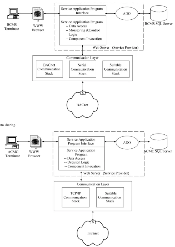
1) BCMS Data Sharing: The BCMS server is connected
with the ACMC server through the intranet, and also connected with the device through the BACnet network, as indicated in Fig. 6. The service application program of the BCMS server is used for data access, monitoring and control logic,
20 IEEE TRANSACTIONS ON AUTOMATION SCIENCE AND ENGINEERING, VOL. 1, NO. 1, JULY 2004
Fig. 6. BCMS data sharing.
Fig. 7. ACMC data sharing.
and component invocation. BCMS users can use the service application program to monitor through the WWW browser. The service application program interface accesses and stores the BCMS SQL database through the active data object. The web server is connected with the BACnet network through the communication layer [6]. Furthermore, the server is connected with the BACnet network through the communication layer comprising the BACnet communication stack that is used for the BACnet protocol communication. The serial communica-tion stack is used for accessing and controlling the serial data
of the system’s element, and the suitable communication stack is used for the requested communication.
2) ACMC Data Sharing: The ACMC server is connected
with the intranet as shown in Fig. 7. The service application program of the ACMC server is used for data access, decision logic, and component invocation. ACMC users can make a de-cision using the service application program through the ser-vice application program interface of the WWW browser. The service application program interface also accesses the ACMC SQL database through the active data object. The web server is
Fig. 8. BCMS facility monitoring window.
connected with the intranet through a communication layer [6]. Furthermore, the server is connected with the intranet through the communication layer with the TCP/IP communication stack that is used for the TCP/IP protocol communication and a suit-able communication stack.
IV. STRUCTURE OF CONTROL AND MONITORING ANDMANAGEMENT
IEMN adapts a three-tier distribution processing architecture for monitoring and control. These are the facility management layer, the BCMS control and monitoring layer, and the ACMC control and management layer.
The facility management layer is the bottom layer of the ar-chitecture for monitoring and controlling the BACnet network. It consists of facilities that can be used to monitor and control for auto-implementation without outside command. The system of the facility management layer’s managing and controlling com-prises the following:
• HVAC system;
• lighting control system;
• fire alarms and sprinkler system; • elevator control system;
• intrusion alert system.
The kernel of the BCMS controlling and monitoring layer is the BCMS server, which comprises databases, controlling pro-grams, and thr user interface. The BCMS controlling and moni-toring layer is adapted to collect and integrate information pro-vided by the bottom layer. It is used to:
• store the integrated information into the database; • send the integrated information to the top layer (the
ACMC control and management layer) by the BACnet protocol [5], [6];
• accept the command from the top layer (the ACMC con-trol and management layer), and send the information to each system of the bottom layer (the facility management layer) after analyzing it;
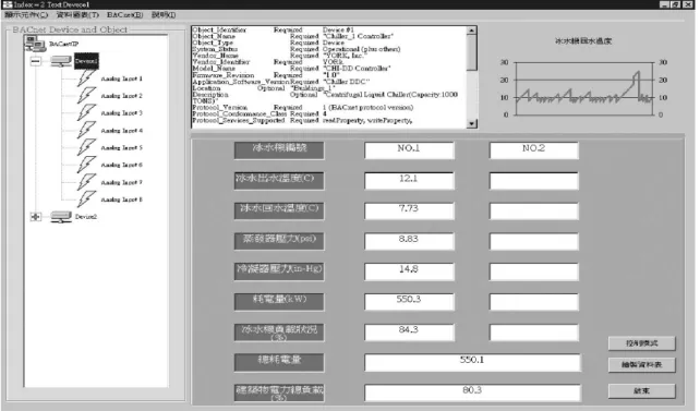
• display the integrated information on the monitoring system.
Controlling programs of the BCMS controlling and moni-toring layer are designed through Visual Basic. Users can access the controlling programs by verifying his/her ID. The results can refer the window as shown in Fig. 8.
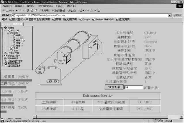
The kernel of the ACMC control and management layer is the ACMC server which comprises the operating system for the ter-minating machine. It consists of the database system, the DSS, and the user interface. The ACMC controlling and management layer monitors and controls the IEMN facilities through the in-tranet. It uses the network to dynamically collect the building’s electric-power information from the BCMS control and moni-toring layer, and to store the information into the ACMC data-base after analyzing it. Users access the controlling programs by verifying their ID. Then, the result is shown in Fig. 9.
There are two models for managing and controlling the system facility: one is the command model, and the other is the strategy model. When a user remotely gives a command to a specific facility according to the command model, such as stopping the air conditioner, the user accesses the ACMC server by verifying his/her ID and accesses the BCMS server by an-other verifying ID. The specific host will be given a command through the service application programs in the BCMS server. This procedure inherently protects security and privacy. If the user follows the strategy model, a user accesses the ACMC server to use the service application programs. The programs will operate and analyze the command, and then store the result into the ACMC database. After that, the ACMC database will send the information to the BCMS database to change the host
22 IEEE TRANSACTIONS ON AUTOMATION SCIENCE AND ENGINEERING, VOL. 1, NO. 1, JULY 2004
Fig. 9. ACMC remote monitoring window.
Fig. 10. Control and management process.
setting (originally set by the BCMS server). The procedures are demonstrated in Fig. 10. In general, the command model is used to issue a special command to the individual facility, while the strategy model is used for changing the operation setting to satisfy every user’s different need.
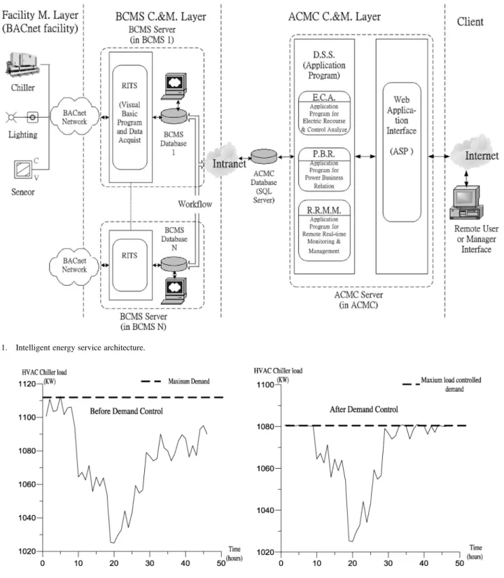
V. INTELLIGENTENERGYSERVICEARCHITECTURE The intelligent energy service architecture processes the data distributed in all the layers’ servers to provide the energy man-agement service. This structure consists of databases, applica-tion programs, and web programs. Fig. 11 shows the intelligent
energy service architecture and data treatment process. The de-scription is illustrated as follows.
1) Real-Time Information Transport Service: The real-time
information transport service (RITS) is provided to send the controlling and the monitoring information of the building au-tomation system to the BCMS databases by using the BACnet protocol and the data acquisition process. The system includes subsystems like the HVAC system, the lighting control system, the fire alarm system, the power meter, the elevator control system, and other building automation system. Users can see the monitoring frame from the servers of the BCMS control and monitoring layer in Fig. 8. After treating and classifying by the
Fig. 11. Intelligent energy service architecture.
Fig. 12. Load control. Before load control (left). After load control (right).
workflow, the data in the BCMS databases are uploaded to the ACMC database, and a real-time output can be generated by the WWW browser. RITS can also accept the control information from the BCMS server and transfer them to the devices.
2) Workflow: Workflow is a group combination of
applica-tion programs for transferring data between databases. Work-flow receives the data collected from the BCMS database and uploads the data to ACMC database after integrating and clas-sifying the data. The output data from the workflow needs to be analyzed to make a proper decision. The output data from
the workflow are sent to the DSS and the results can be output via the WWW browser. The workflow can also accept the con-trol command from the ACMC server and transport them to the BCMS databases and to the devices via RITS.
3) Decision Support System : DSS in the ACMC server
con-sists of application programs for operation of decision logic. DSS receives the data from the workflow. The DSS analyses the data and divides them into three different functional groups: remote real-time monitoring and management (RRMM), elec-trical power recourse and control analyses (ERCA), and power
24 IEEE TRANSACTIONS ON AUTOMATION SCIENCE AND ENGINEERING, VOL. 1, NO. 1, JULY 2004
business relationship (PBR). The output from RRMM, ERCA, and PBR can also be generated by the WWW browser. The de-scription of RRMM, ERCA, and PBR is listed as follows.
a) Remote real-time monitoring and management:
RRMM is in charge of managing, monitoring, and control of the facilities in the domain. Users can get the status of each building’s systems and facilities using this service through a WWW browser (see Fig. 9). Users can also issue commands to a specific facility or a specific building via the WWW browser. The command will then be carried out according to the control process in Section IV.
b) Electrical power recourse and control analyses:
ERCA is in charge of managing and dispatching electric-power resources in the domain. Users can get the electrical power status report of the facilities of each building from this service through the WWW browser. Furthermore, they can issue commands to adjust and to arrange the use of electrical-power resources. The procedure in Section IV allows for the imple-mentation of the command. Fig. 12 displays the result of using the remote load control of a HVAC chiller. When the load control is not in use, the HVAC chiller experiences huge load changes. The load control, on the other hand, forces the chiller to shut down and reduces the maximum load. This process can thus conserve energy.
c) Power business relationship: PBR is managed by the
ACMC of the IEMN. The ACMC provides the cost analysis, the cost forecast, and the power adjustment suggestion for every customer, based on the history of the system. Users can obtain the suggestion information through the WWW browser. The re-cent advancement in data warehousing and data mining can also help provide more practical information to the system. The intel-ligent network can then be conveniently realized through work-flow and DSS.
VI. CONCLUSION ANDFUTUREDEVELOPMENT This paper proposed an IEMN based on the BACnet protocol and the surrogate object-communication model to interconnect the BACnet, intranet, and Internet. The network facilitates a three-layered hierarchy: the ACMC control and management layer, the BCMS control and monitoring layer, and the facility management layer for management. Except for the hardware structure, the IEMN also provides intelligent energy service ar-chitecture with intelligent decision making for energy manage-ment. A remote user can access the IEMN through the Internet. The hierarchy of the IEMN provides inherent security and pri-vacy. The power companies can provide more efficient services with the information offered by the IEMN. The future develop-ment of the IEMN includes the developdevelop-ment of platform tech-nology and application services. For the platform techtech-nology, the IEMN can be based upon more efficient platform tools such as the XML. For the application service, the IEMN can adapt the new database technology to provide more complete and more efficient business services.
REFERENCES
[1] A. C. W. Wong and A. T. P. So, “Building automation in the 21st cen-tury,” in Proc. 4th Int. Conf. Advances in Power System Control,
Oper-ation, and Management (APSCOM’97), Nov. 1997, pp. 819–824.
[2] T. Derek and J. Clements-Croome, “What do we mean by intelligent buildings,” Automat. Construct., vol. 6, no. 5–6, pp. 395–400, 1997. [3] A. T. P. So, W. L. Chan, and W. L. Tse, “Building automation on the
in-formation superhighway,” Trans. ASHRAE, vol. 104, no. 2, pp. 176–191, 1998.
[4] S. M. Tsai, S. S. Wu, S. S. Sun, and P. C. Yang, “Integrate home service network on intelligent intranet,” IEEE Trans. Consumer Electron., vol. 46, pp. 499–504, Aug. 2000.
[5] A Data Communication Protocol for Building Automation and Control
Networks, AnnexJ-BACnet/IP, ASHRAE Standard, 1995.
[6] A Data Communication Protocol for Building Automation and Control
Networks, ASHRAE Standard, 1995.
[7] C. K. Haakenstad, “The open protocol standard for computerized building system BACnet,” in Proc. 1999 IEEE Int. Conf. Control
Applications, vol. 2, Aug. 1999, pp. 1585–1590.
[8] G. B. Cebasek, J. J. Gloudeman, D. A. Gottschalk, and D. E. Ras-mussem, “Communication System for Distributed-Object Building Automation System,” U. S. Patent 6 104 963, Aug. 15, 2000. [9] M. A. Radtke, “Migrating an energy management system to a
net-worked architecture,” IEEE Trans. Power Syst., vol. 11, pp. 409–414, Feb. 1996.
[10] G. Clark and P. Mehta, “Artifical intelligence and networking in inte-grated building management systems,” Automat. Construct., vol. 6, no. 5–6, pp. 481–498, 1997.
[11] J. T. K. Mar, T. M. Liu, and L. F. Wu, “New energy management system architectural design and intranet/internet applications to power system,” in Proc. 1999 IEEE Int. Conf. Energy Management Power Delivery
(EMPD ’98), vol. 1, Mar. 1998, pp. 207–212.
[12] M. R. Brambley, K. Gowri, and D. P. Branson, “DDC and the web,”
ASHRAE J., vol. 42, no. 12, pp. 38–44, 2000.
[13] S. Wang and J. Xie, “Integrating building management system and fa-cilities management on the internet,” Automat. Construct., vol. 11, no. 6, pp. 707–715, 2002.
[14] Q. Zhao, G. Huang, X. Wu, and X. Luo, “A software architecture for power market supporting system and reengineering of legacy EMS,”
IEEE Trans. Power Syst., vol. 18, pp. 191–197, Feb. 2003.
[15] J. Desbonnet and P. Corcoran, “System architecture and implementation of a CEBus/internet, gateway,” IEEE Trans. Consumer Electron., vol. 43, pp. 1057–1062, Nov. 1997.
[16] E. Topalis, G. Orphanos, S. Koubias, and G. Papadopoulos, “A generic network management architecture targeted to support home automation networks and home internet connectivity,” IEEE Trans. Consumer
Elec-tron., vol. 46, pp. 44–51, Feb. 2000.
[17] G. Park, “The remote control system for the next generation air condi-tioners,” IEEE Trans. Consumer Electron., vol. 47, pp. 168–178, Feb. 2001.
Hsiao-Yi Huang was born in Taipei, Taiwan, R.O.C.,
in 1969. He received the M.Sc. degree in naval ar-chitecture and ocean engineering, National Taiwan University, Taipei, Taiwan, R.O.C., in 1997. He is working toward the Ph.D. degree in mechanical en-gineering at the same university.
His current research interests include supervisory control of distributed systems, energy management, and microelectromechanical systems design.
Taipei Section in 1992. During his study at Berkeley, he received the IBM Grad-uate Fellowship for 1984–1985. He is a member of the ASME.
Feng-Chu Ou received the M.S. and the Ph.D.
de-grees in mechanical engineering from the National Central University, Taiwan, R.O.C., and the National Taiwan University, Taipei, Taiwan, R.O.C., in 1990 and 2003, respectively.
Since 1990, he has been a Lecturer in the Department of Mechanical Engineering at the K.W. Institute of Technology, Taipei, Taiwan, R.O.C., and Director of the Applied Pneumatics and Hydraulic Control Laboratory.
Dr. Ou received the PTP scholastic honor society in 1990.