An Attempt to Build a WEB-based Tele-Radiology Collaborated
Diagnosis System
Bo-Shen Tsao
a, Yu-Tai Ching
a, Mon-YuanY Lin
a, James SJ Chen
b, and Wen-Jeng Lee
ba
Department of Computer and Information Science
National Chiao Tung University, Hsin Chu, Taiwan
b
Department of Radiology
National Taiwan University, Taipei Taiwan
ABSTRACT
We present a web-based collaborated diagnosis system developed using Java programming language. The system allows more than two physicians to look at the same images, to discuss through a chat box, and to make diagnosis collaboratively. The system provides tools such as window and value setting that physicians generally need. Beside the tools, we are implementing different tools for the system such as a volume rendering algorithm and an animation playback method. To make the system easily accessed, all the physician need is a web browser.
Keywords: PACS, collaborated diagnosis system, Java programming
1. INTRODUCTION
The World Wild Web has a great progress in the recent years. Many applications use the Web as a tool to develop a distal interactive system such as the Computer Assisted Education, Video Conference, … etc. In medical application, people starts to utilize computer network to provide better service in clinics. This work is an attempted to build a web based collaborated diagnosis system. One possible application of such system is to support medical services in the country site where there is insufficient medical resource. Another possible application is to provide a distal discussion environment for two or more physicians to discuss on medical images. Without such system, a way to make distal discussion would start with sending a copy of images to all the physicians and then discussing through telephone call. This way is inefficient and inaccurate. Using the proposed collaborated diagnosis system can prevent this problem.
We developed the system using the Java programming language so that the system can run on any platform independent of the operating system. Because the client end of the system is developed as Java applet, the physicians only need a web-browser. In the following, we shall first describe the system outline. We then present the implementation for each module in the system.
2. SYSTEM OUTLINE
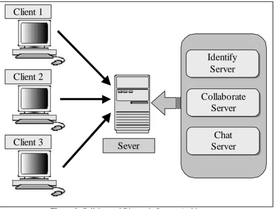
We used Server-Client architecture to develop this system. All the images are stored in the server site. If the images are in one of the client sites, the client should upload the images to the server site. All the operations are issued from client sites. The server makes a proper response upon a request.
At the server end, according to the tasks involved, there are theIdentify-Server, theCollaborate-Serverand theChat-Server(Figure 1). TheIdentify-Serveris in charge of the login process of users. It validates users and relays the information of valid users to the Collaborate-Server and the Chat-Server. The Collaborate-Server is the most important module among all these modules. It receives requests from the clients, and then makes proper process upon the requests. TheChat-Serverworks as a chat room server.
Figure 1. Collaborated Diagnosis System Architecture
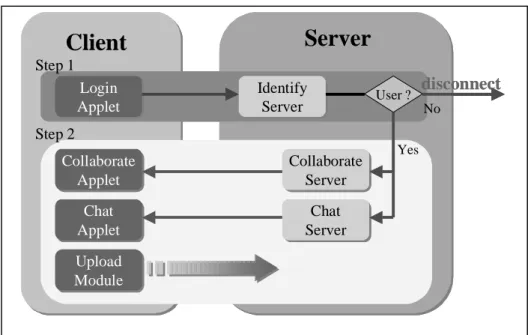
At the client end, there are corresponding modules to the modules in the server end (Figure 2). They are the Login-Applet, the Collaborate-Applet, and the Chat-Applet. In addition to these modules, there is an Upload-File-Modulethat provides client users to upload image data to the server site.
Figure 2. WEB-based Collaborated Diagnosis System Client and Server
Sever
Client 1
Client 2
Client 3
Collaborate
Server
Identify
Server
Chat
Server
Log in
Applet
Collaborate
Applet
Chat
Applet
Identify
Server
Collaborate
Server
Chat
Server
Upload
Module
The flow of tasks execution is shown in Figure 3. The modules in the server end must be executed first. These modules will wait for the requests of connection from the clients. When a user try to log in the system, theIdentify-Server
receives user’s ID and password and checks if the user is a valid user. If the user is a valid user, then the Identify-Server relays information regarding the user to the Collaborate-Serverand theChat-Server. The user can then connect to these two modules. For security consideration, the Collaborate-Server and the Chat-Server
need such information received from theIdentify-Server. This prevents a user to connect to the Collaborate-Server or theChat-Server directly without authentication. If the user is identified as a valid user, the connection between server end and client end will be created. Then user can proceed the collaborated diagnosis.
Figure 3. Flow-chart of the WEB-based Collaborated Diagnosis System 3. SERVER
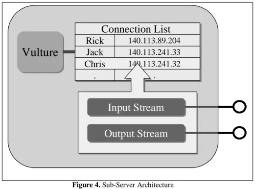
We now discuss the implementation of the modules in the server end. Although we split it into three modules as described before, their base structures (Figure 4) are the same. We describe the details of the base structure in the following.
As shown in Figure 4, there are two main components, the “Vulture” and the “Connection List”, in the structure. The “Connection List” is a table that keeps information of all the users in this system. These informations of users are stored as objects called “client object”. In each of the client objects, there are input stream and output stream that are messages received from or send to clients. The “Vulture” is the manager of the “Connection List”. It uses the information of the client objects in “Connection List” to broadcast data to all users or to relay data to a specific user. Furthermore, it needs to confirm that all the connections between server and users are not broken. We describe each module in the following. IDENTIFY-SERVER
TheIdentify-Serveris in charge of the identification of a login user. When a user logs in the system by the Login-Applet, theIdentify-Servercreates a client object for this user. It identifies a valid user by examining the ID and the password. If the user is illegal, it disconnects the connection to the user and removes the client object from the “Connection List”. Otherwise, the Identify-Server relays information to the Collaborate-Server and the
Chat-Serverto complete user identification. COLLABORATE-SERVER
In theCollaborate-server, it checks the user’s validation by examining ID and IP first for security reason. If the user is valid, it creates a client object for the user and add this client object to the “Connection List”, otherwise it disconnects the connection to the user. When the user starts using the Collaborate-Applet, the
Collaborate-Identify Server Identify Server Collaborate Server Collaborate Server Chat Server Chat Server
Client
Login Applet Login Applet Collaborate Applet Collaborate Applet Chat Applet Chat Applet Upload Module Upload ModuleServer
User ? No Yes Step 1 Step 2disconnect
Identify Server Identify Server Collaborate Server Collaborate Server Chat Server Chat ServerClient
Login Applet Login Applet Collaborate Applet Collaborate Applet Chat Applet Chat Applet Upload Module Upload ModuleServer
User ? No Yes Step 1 Step 2disconnect
CHAT-SERVER
The implementation of theChat-Serveris simple. It just needs to receive text message from clients, and broadcast the same message to all the users or to a specific user upon requests.
Figure 4. Sub-Server Architecture 4. CLIENT
As shown in Figure 2, there are corresponding modules to the modules in the server end. These are theLogin-Applet, the Collaborate-Applet, and theChat-Applet. Besides, there is an Upload-File-Module. Among these modules, the most important module is theCollaborate-Applet.
The implementation of theLogin-Appletand theChat-Appletare almost the same. They simply send text message to the server and receive message from server. The only difference is that theChat-Appletneeds to receive message from server and always keeps alive, but the Login-Appletneed not. And there is Upload-File-Module. It is a simple CGI to support users to upload files to server site.
The implementation of theCollaborate-Appletis much more complex since all the tools for collaborated diagnosis are in this module. Basically, the Collaborate-Appletworks like theChat-Applet. The differences are that it needs to handle all the events produced by the tools and the data communication between server and client is more complex. In the following, we present the tools provided in theCollaborate-Applet.
PRIMARY COLLABORATED DIAGNOSIS TOOLS
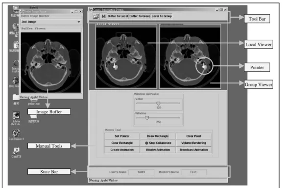
For a collaborated diagnosis system, the most important function is to support more than two physicians to look at the same image at the same time. The Collaborate-Applet provides a “Image Buffer”, a “Local Viewer”, and a “Group Viewer” to support this function. Users load the images from the server site and store the images in the “Image Buffer” temporally. The user needs to choose one of the images in the “Image Buffer” to display in the “Local Viewer” or in the “Group Viewer”. In the “Local Viewer”, user can use provided tools to manipulate the image. The other users cannot see this image in the “Local Viewer”. If a user wants to send the resulted image to the others, the user has to get the “Master token” from the server first, then put the image into the “Group Viewer”.
Vulture
Vulture
Connection List
140.113.89.204
Rick
Jack
140.113.241.33
.
.
Chris
140.113.241.32
Input Stream
Input Stream
Output Stream
Output Stream
Vulture
Vulture
Connection List
140.113.89.204
Rick
Jack
140.113.241.33
.
.
Chris
140.113.241.32
Connection List
140.113.89.204
Rick
Jack
140.113.241.33
.
.
Chris
140.113.241.32
Input Stream
Input Stream
Output Stream
Output Stream
TheCollaborate-Appletprovides some useful tools to manipulate images. For example, one of the physicians can put marks or draw rectangles in the image to bring attention of the others to the region (Figure 5). Another useful tool is window-value adjustment of an image. This tool is usually used to enhance the region of interest in the image.
In addition to these fundamental tools, the system also provides an animation playback function and a volume-rendering tool to created 3D images. We describe these two advanced operations in the following.
Figure 5.Interface of WEB-based Collaborated Diagnosis System ANIMATION
Playing animation sequence is helpful in gaining some functionality information such the wall motion of a heart. The animation of a sequence of images is in the format we defined. The system consisted of two parts- creation of the animation file and displaying the animation file. To create the animation file, a user must load the set of images into the Image buffer. The user can then select the images that will be in the animation sequence. Finally the animation sequence is created. These files are stored in the server site and then transmit to the clients under request.
In the module of displaying animation sequence, an end user can request for an animation file from the Server. If the user is the Master Token owner, the user can broadcast the animation sequence to all the users. Otherwise a window for displaying the animation sequence is created in the client site. The animation is not synchronized when it is broadcasted to all the end users.
VOLUME RENDERING
The system provides a tool for volume rendering of a stack of images. The algorithm we implemented is the Shear-Warp rendering algorithm. Similar to that in displaying an animation sequence, a user can request for the operation of volume rendering a stack of images. The rendering is carried out in the server site. The user receives the reconstructed image from the server. Only the Master Token owner can broadcast the result to all the end users. The volume rendering process needs very large memory space and CPU time. That is one of the reasons that volume rendering is designed to be carried out in the server site.
5. FUTURE WORK Image Buffer Tool Bar Pointer Local Viewer Group Viewer State Bar Manual Tools Image Buffer Tool Bar Pointer Local Viewer Group Viewer State Bar Manual Tools
The system can be extended by adding components as we have done by adding volume rendering algorithm into the system. A possible component is a databases access system to support integration of other databases system such as HIS or RIS. We also plan to build an authentication system for physician to edit the charts of patients.
Another work will be to improve the chat system we have implemented. We also consider to include the video conference technique to this system. This will become practical when the bandwidth of the network is sufficient large.
6. REFERENCES
1. HK Huang, R. A, et al(1993). “Second generation PACS at UCSF.” Radiology 189:290 2. S Zink, C. J. (1993). “Medical image databases.” Investigative Radiology 28(4):366-372. 3. Robert Eckstein, Marc Loy, and dave Wood, JavaTMSwing, O’Reilly & Associates, 1998 4. Naughton, P. and Schildt, H., The Complete Reference, Java2, McGraw-Hill, 1997. 5. Eckel, Bruce, Thinking in Java, Prentice-Hall, 1998.