Design of Parallel-Coupled Microstrip Filters
With Suppression of Spurious Resonances
Using Substrate Suspension
Jen-Tsai Kuo, Senior Member, IEEE, Meshon Jiang, and Hsien-Jen Chang
Abstract—Substrate suspension is used to suppress the spurious response of microstrip bandpass filters at twice the passband fre-quency(2 ). It is known that a proper height of substrate sus-pension can be used to equalize the even- and odd-mode phase ve-locities for coupled microstrip lines. In this paper, this property is applied to design the coupled stages of a parallel-coupled line filter so that the spurious response at2 can be completely suppressed. The individual image impedance for each coupled stage is changed accordingly. Required filter design formulas are derived for a se-ries of coupled stages having different image impedances. Several filters made on a substrate of relative high dielectric constant are designed and fabricated. The measured results show that a rejec-tion level of better than 40 dB to the spurious resonance at2 can be obtained.
Index Terms—Image impedance, parallel-coupled microstrip filter, spurious response, suspended substrate.
I. INTRODUCTION
M
ICROSTRIP bandpass filters made of a cascade of parallel coupled-line sections have been widely used in many microwave and millimeter-wave systems. This type of filter is popular since it has a planar structure, good repetition, and a simple synthesis procedure [1]. The rejection level in the upper stopband of this type of filter, however, is usually degraded by the spurious response at twice the passband frequency . This is because that the even and odd modes of each coupled section have different phase velocities [2]. The modal phase velocities, however, are assumed identical for the ease of synthesis. Obviously, if the spurious resonance at can be eliminated completely, the width and rejection level of the upper stopband and the symmetry of the passband response can be greatly improved simultaneously.Several techniques have been proposed to tackle this problem [2]–[6]. An over-coupled section is effective in suppressing the spurious response [2]. The stepped-impedance resonator (SIR) filters [3], [4] are capable of pushing the first parasitic harmonic to far beyond . A combination of different SIR structures can be adopted for spurious-free bandpass filters with a wide stopband [3]. An SIR with a large impedance ratio can provide a good rejection level within a wide stopband [4].
Manuscript received May 6, 2003, revised June 27, 2003. This work was supported in part by the National Science Council, Taiwan, R.O.C. under Grant NSC 91-2213-E-009-126, and by the Joint Program of the Ministry of Education and the National Science Council under Contract 89-E-F-A06-2-4.
The authors are with the Department of Communication Engineering, National Chiao Tung University, Hsinchu 300, Taiwan, R.O.C. (e-mail: jtkuo@cc.nctu.edu.tw).
Digital Object Identifier 10.1109/TMTT.2003.821247
In [5], simulation and experiment indicate that the rejection of the filter at can be improved by decreasing the linewidths of the input/output coupled resonators to less than those of the input/output microstrips, and by reducing the gap size for keeping the strong coupling for input/output resonators. The wiggly coupled microstrip filter in [6] is also successful in suppressing the spurious response. Using a continuous pertur-bation of the width of the coupled lines following a sinusoidal law, the wave impedance is modulated so that the harmonic passband of the filter is rejected, while the desired passband response is maintained virtually unaltered.
The field-theoretical study in [7] indicates that inserting an appropriate dielectric layer underneath the substrate can elimi-nate the difference between the even- and odd-mode phase ve-locities of coupled microstrips. As reported in [7], where the gap size is twice the linewidth, the phase velocities for both the even and odd modes can be made very close to that of the quasi-TEM mode for a single suspended microstrip in a very wide frequency range. In our previous paper [8], this phase velocity equalization technique is used to design the coupled stages for a parallel-cou-pled microstrip filter. The spurious response of this filter can be suppressed by over 30 dB, as compared with that of a mi-crostrip filter without substrate suspension. It is noted that, in [8], the suspension heights required for each coupled stage, to have equalized modal phase velocities, can be different from one another, and the final uniform suspension height is obtained via an optimization.
In this paper, the concept in [8] is extended to design par-allel-coupled microstrip filters on a suspended substrate for a given suspension height. Of the filter, the coupled microstrips of each coupled stage have identical even- and odd-mode phase velocities so that the spurious response at can be suppressed completely. No optimization for any circuit dimension is re-quired here. It is found that the height, within a certain range, can be a premise for constructing parallel-coupled filters free of spurious responses. Since the image impedance of each cou-pled stage deviates from 50 , the design parameters for the filter have to be modified accordingly. Detailed design formulas will also be derived. Several parallel-coupled microstrip filters are fabricated on suspended structures with various suspension heights, and the measured results are compared with the simu-lations.
This paper is organized as follows. Section II explores the eigenmode phase velocity equalization for coupled microstrips using substrate suspension. Section III formulates the design of parallel-coupled microstrip filters, of which each coupled stage
84 IEEE TRANSACTIONS ON MICROWAVE THEORY AND TECHNIQUES, VOL. 52, NO. 1, JANUARY 2004
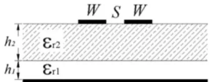
Fig. 1. Cross section of suspended coupled microstrip lines.
Fig. 2. Dispersive " and " for four suspended coupled microstrip structures." = 1; " = 10:2. The circuit dimensions are given is Table I.
has its own image impedance. Section IV presents the simulated and measured results of six fabricated filters, and Section V draws a conclusion.
II. EQUALIZING MODAL PHASE VELOCITIES
USINGSUBSTRATESUSPENSION
Suppose that we are designing a bandpass filter with center frequency GHz and free of spurious resonance at using a substrate with and thickness mm. The reason for choosing this relative high substrate is to have a circuit of smaller size, compared with those on substrates with lower . The challenge with this substrate to the filter design is that the deviation between and , the even- and odd-mode phase velocities, respectively, will be relatively large. This will increase the difficulty in suppressing the spurious response at
.
For the suspended structure shown in Fig. 1, the height of sub-strate suspension, i.e., , can be adjusted to equalize and at [7]. The full-wave spectral-domain approach (SDA) pro-gram in [9] is invoked. It is worth mentioning that a full-wave analysis for the inhomogeneous structure is essential since the equalization of and at can no longer exist at different frequencies. It can be shown that once and for each cou-pled stage have an intersection at , the filter will be free of spurious response at this frequency, and the width of the upper stopband can be at least doubly extended. Fig. 2 shows the dis-persive and , the even- and odd-mode effective dielectric constants, respectively, for four suspended coupled microstrip lines. The detailed dimensions of the structures are listed in Table I. It is found that the required value of varies as ei-ther or changes. As shown in Fig. 2, when operation fre-quency moves away from , the case with a relatively wide
TABLE I
CIRCUITDIMENSIONS OFSUSPENDEDCOUPLEDLINES INFIG. 2. h = 1:27 mm
Fig. 3. Requiredh =h ratios to have = for various S=h and W=h at 4.9 GHz for suspended coupled microstrip lines with" = 1; " = 10:2; andh = 1:27 mm.
microstrips and narrow gap (structure 3) has the largest devia-tion in modal effective dielectric constants.
Not shown here is that the average value of and of the coupled lines of the same dimensions, as in Table I, without substrate suspension is 6.2, which is 10% higher than that of the suspended coupled microstrips. It means that the advantage of resulting in a smaller circuit size using a relatively high sub-strate still holds for the suspended structures investigated here.
As indicated in Table I, given ratios of and , a special ratio can be obtained for . Fig. 3 plots the required curves against for varying from 0.1 to 2.0. The lower limits for and are purposely chosen to be 0.1 since mm (or 50 mil) and
mm is the best resolution for a metallic strip width and gap size that can be obtained using a general wet chemical-etching process. As indicated in Fig. 3, when either or is increased, is increased. It is noted that the plots are valid only when GHz. If the operation frequency changes, the plots should be recalculated. Also, (or ) at any two points on one curve are not necessarily the same, and their values are not indicated in the plots. From Fig. 3, say, , the possible ratios to have are between 0.2 and 1.1 if . The possible ratios for equalizing and change as the ratio is changed.
III. FILTERDESIGN ON ASUSPENDEDSUBSTRATE
The modal characteristic impedances and of cou-pled microstrip lines should be calculated to establish a design graph for each coupled stage. The a filter of Chebyshev type or maximally flat response can then be synthesized based on the
(a)
(b)
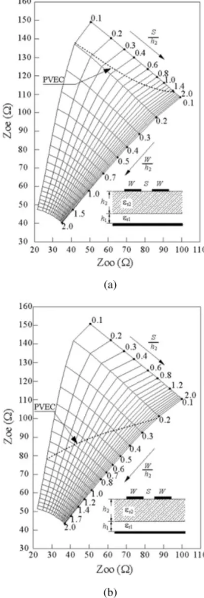
Fig. 4. Even- and odd-mode characteristic impedance design graphs for suspended coupled microstrip lines. (a)h = 0:06 mm. (b) h = 0:10 mm. The substrate hash = 1:27 mm and " = 10:2. PVEC = the phase velocity equalization curve.
classical method [1]. Of each coupled section, and are determined by the image impedance and the admittance inverter specified by the equivalent circuit of the filter.
The intuitive way for designing filters with suppression of spurious responses using a substrate suspension can be as fol-lows. Apply the classical synthesis method to determine the di-mensions of each coupled stage. Insert an air layer of proper height underneath the substrate to make . Each coupled section, however, has its own value, and the ground “plane” for the whole filter becomes an uneven surface. For example, in the four-stage or third-order Chebyshev filter in [8], the values are 0.11 and 0.16 mm for the end and middle stages, re-spectively.
It is the purpose here to formulate the design of filters on a suspended substrate with a uniform suspension height. Fig. 4(a) and (b) shows the even- and odd-mode characteristic impedance design graphs for suspended coupled microstrips with mm and mm, respectively. The substrate has mm and . If a horizontal line for
Fig. 5. Development of an equivalent circuit for derivation of design equations for an nth-order parallel-coupled line filter. (a) Circuit layout. (b) Equivalent circuit of admittance inverters. (c) Approximated equivalent circuit. (d) Equivalent circuit of (c).
is drawn in Fig. 3, the intersection of this line and each constant curve specifies a ratio that has . It can be seen that, for this particular substrate, if the ratio can be no less than 0.06, the choice of will have a large degree of freedom. The intersection points form a curve, herein called the phase velocity equalization curve (PVEC), which can be plotted with the design graphs, as shown in Fig. 4. It means that when the dimensions of each coupled stage are chosen from the points on the PVEC, then each stage will have . It is noted that for the PVEC in Fig. 4(a), the widths of the coupled lines are limited to be from to , and is limited to within 110 to 140 , while can be freely chosen from 40 to 95 .
It is found possible to design filters on a suspension height of within 0.05 and 0.12 mm, including the fabrication limitations to the resolution of linewidths and gap sizes of 0.15 mm for filter fractional bandwidths of up to 25%. A large bandwidth may lead to the linewidth or gap size smaller than the resolution.
Now that only the and on the PVEC can be chosen, more general formulas for filter design should be developed since the two variables and locate on a curve, which is of only one dimension. The design method of a filter with arbitrary image impedance [10] can be extended to meet this purpose. Developed in [10] is that all coupled stages have an image impedance different from the reference system impedance (50 ). Obviously, if the image impedances of all the coupled stages are allowed to be different from one another, the filter design on a suspended substrate can be completed.
Fig. 5(a) plots the layout of an th-order parallel-coupled mi-crostrip filter, of which each of the coupled stages may have its own image admittance. Since a coupled stage can be
86 IEEE TRANSACTIONS ON MICROWAVE THEORY AND TECHNIQUES, VOL. 52, NO. 1, JANUARY 2004
approximated by two quarter-wave lines with an admittance in-verter in between [1], the equivalent circuit for Fig. 5(a) can be drawn in Fig. 5(b). The characteristic admittances for the quarter-wave sections are . All ’s, including , the system admittance, can be different from one another. Here, let all the filters be of Chebyshev type of an odd order so that and so on. Thus, only pairs of need specifying. In Fig. 5(b), there is a cascade of two sections of transmission lines, with different characteristic admittances, between any two adjacent admittance inverters. It has been shown in [11] that a cascade of such two quarter-wave lines of characteristic admittances and can be approximated by a half-wave line of character-istic admittance . Thus, the circuit in Fig. 5(b) can be further approximated by the equivalent circuit in Fig. 5(c). The admittance seen looking toward the inverter can be ex-pressed as [10]
(1) where and
(2) (3) Thus, for the equivalent circuit of a filter of order
in Fig. 5(d), the susceptance of the th resonator can be obtained as
(4a) (4b) for for even and
for odd. From (4), the corresponding susceptance slope parameter can be derived using
(5) The inverters can be expressed by the following formulas [12]: (6a)
to (6b)
(6c) where is the fractional bandwidth and ’s are the element values of low-pass filter prototype. The even- and odd-mode characteristic impedances for each coupled stage are determined by
(7a) (7b)
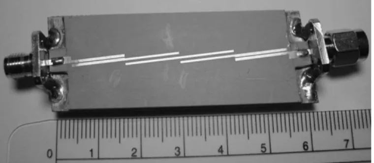
Fig. 6. Photograph of a tested filter (filter F in Table II).
for for even and for
for odd. In (7), can be obtained by (8a) (8b) IV. SIMULATED ANDMEASUREDFILTERRESPONSES
Six bandpass filters are made to demonstrate the design of bandpass filters free of spurious response at . The fabrication procedure is as follows. First, the RT/Duroid 6010 microwave laminate ( and mm) and a low-cost FR4 printed circuit board (PCB) are used for the substrate and ground plane, respectively. A plastic film of proper thickness, measured using a digital caliper, is then sandwiched between the circuit substrate and PCB. For example, the thickness of a PP2900 transparency film from 3M Korea is 0.1 mm. Next, the center pins and panel mounts of the subminiature A (SMA) connec-tors are soldered to the circuit ports and ground plane, respec-tively. The strength of the soldered portions on both ends of the circuit guarantees a uniform air gap between the flat substrate and ground plane. Finally, the plastic film is removed when the circuit is measured. Fig. 6 is a photo of one of the tested filters (filter F in Table II).
In designing a third-order filter, only two points of the PVEC in Fig. 4 are required. It is noted that when a point on the PVEC is chosen, the second point cannot be chosen freely since and depend on each other, as indicated in (8). Given a suspension height, and are determined as follows. First, the PVEC curve in Fig. 4 is expressed in a form as , e.g., a cubic spline [13]. Next, define a complex error function
(9) Then insert (1)–(8) into a program. Finally, use a root-searching algorithm, e.g., the Muller’s method or Newton’s method [13], to find the solutions. A simpleFORTRANprogram of less than 50 statements can perform this job well. Only several iterations can complete the design with an initial guess of . The execution of this program takes less than 0.1 s using a PC of today.
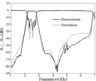
With a center frequency GHz and a Chebyshev response with 0.1-dB passband ripple, the six filters have their respective suspension heights. The simulation and measured re-sponses are plotted in Figs. 7–12, and the value and de-tailed dimensions of each coupled stage of the filters are listed
TABLE II
SPECIFICATIONS ANDDIMENSIONS FOR THESIXFABRICATEDSUSPENDEDFILTERS
Fig. 7. Simulation and measurement responses of filter A. Circuit parameters are in Table II.
Fig. 8. Simulation and measurement responses of filter B. Circuit parameters are in Table II.
in Table II. It has been verified that the maximal relative devia-tion of and for the coupled stages is 0.035%.
The responses of filters A–C are plotted in Figs. 7–9, and their substrate suspension heights are and mm, respectively. The order of filter B is five, and those of A and C are three. They are designed to have a fractional bandwidth %. It has been shown in [8] that the spurious responses
Fig. 9. Simulation and measurement responses of filter C. Circuit parameters are in Table II.
Fig. 10. Simulation and measurement responses of filter D. Circuit parameters are in Table II.
at are higher than 10 dB for the filters with similar specifi-cations on a substrate of without suspension. It can be observed that the small peaks near GHz are below or close to 50 dB. Thus, the proposed method achieves a suppres-sion of 40 dB to the spurious responses. It can be observes that the dips of the responses of filters A–C are better than 60 dB. Filters D–F are designed to have % given and mm, and their results are shown in
88 IEEE TRANSACTIONS ON MICROWAVE THEORY AND TECHNIQUES, VOL. 52, NO. 1, JANUARY 2004
Fig. 11. Simulation and measurement responses of filter E. Circuit parameters are in Table II.
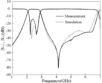
Fig. 12. Simulation and measurement responses of filter F. Circuit parameters are in Table II.
Figs. 10–12, respectively. Filter E is of order five, and filters D and F are of order three. The rejection levels at the response dips are better than 70 dB. The small peaks near GHz for filter D are close to 45 dB. The Ansoft High Frequency Structure Simulator (HFSS) is used for the simulation in this study. It can be observed that all the measured responses have a good agreement with the simulation in both the passband and stopband.
The conditions and parameters of Figs. 7–12 can be further explained as follows. For each , we have to establish a PVEC and even- and odd-mode characteristic impedance design graphs since and depend on the thickness of the air gap. Once the fractional bandwidth and ripple level are known, the element values of the low-pass filter prototype can be obtained. In designing the third-order filter A, with an initial guess , one obtains the image impedances for the first and second coupled stages and from the solutions of (9). It is noted that and . From (7), one
can then obtain the characteristic impedances of the end and middle stages and , which are used to deter-mine the dimensions of the coupled stages, as listed in Table II. Since the two points and locate on a PVEC, each coupled stage is guaranteed to have identical even-and odd-mode phase velocities.
It is noted that there are zigzags in all the responses shown in Figs. 7–12 at . This reflects the fact that the even-and odd-mode phase velocities of the coupled lines of each cou-pled stage for these filters have very close values.
V. CONCLUSION
This research has combined a field-theoretical study on the propagation characteristics of suspended microstrip lines and a flexible skill for design of parallel-coupled line filters. Substrate suspension is an effective approach in designing microstrip bandpass filters with suppression of the spurious resonance at twice the passband frequency. The design is based on a theory that the even- and odd-mode phase velocities of suspended coupled microstrips can be equalized on a substrate with a proper suspension height. A method has been developed for approximately synthesizing parallel-coupled microstrip filters of which each coupled stage can be of arbitrary image impedance. The simulation and measured results show a good agreement. As compared with the structure without suspension, this design has a suppression of 40 dB to the spurious responses.
ACKNOWLEDGMENT
The authors thank the National Center for High-Performance Computing, Hsinchu, Taiwan, R.O.C., for the software and hardware facilities, which are essential for the EM simulation of this study.
REFERENCES
[1] D. M. Pozar, Microwave Engineering, 2nd ed. New York: Wiley, 1998. [2] B. Easter and K. A. Merza, “Parallel-coupled-line filters for inverted-mi-crostrip and suspended-substrate MICs,” in 11th Eur. Microwave Conf.
Dig., 1981, pp. 164–167.
[3] M. Makimoto and S. Yamashita, Microwave Resonators and Filters
for Wireless Communication—Theory and Design. Berlin, Germany: Springer, 2001.
[4] L. Zhu and K. Wu, “Accurate circuit model of interdigital capacitor and its application to design of new quasi-lumped miniaturized filters with suppression of harmonic resonance,” IEEE Trans. Microwave Theory
Tech., vol. 48, pp. 347–356, Mar. 2000.
[5] C. Wang and K. Chang, “Microstrip multiplexer with four channels for broadband system applications,” Int. J. RF Microwave Computer-Aided
Eng., pp. 48–54, Nov. 2001.
[6] T. Lopetegi, M. A. G. Laso, J. Hernández, M. Bacaicoa, D. Benito, M. J. Garde, M. Sorolla, and M. Guglielmi, “New microstrip ‘wiggly-line’ filters with spurious passband suppression,” IEEE Trans. Microwave
Theory Tech., vol. 49, pp. 1593–1598, Sept. 2001.
[7] J. P. Gilb and C. A. Balanis, “Pulse distortion on multilayer coupled microstrip lines,” IEEE Trans. Microwave Theory Tech., vol. 37, pp. 1620–1628, Oct. 1989.
[8] J.-T. Kuo and M. Jiang, “Suppression of spurious resonance for mi-crostrip bandpass filters via substrate suspension,” in Asia–Pacific
Mi-crowave Conf., Kyoto, Japan, Nov. 19–22, 2002, pp. 497–500.
[9] J.-T. Kuo and T. Itoh, “Hybrid-mode computation of propagation and at-tenuation characteristics of parallel coupled microstrips with finite met-allization thickness,” IEEE Trans. Microwave Theory Tech., vol. 45, pp. 274–280, Feb. 1997.
[10] D. Ahn, C.-S. Kim, M.-H. Chung, D.-H. Lee, D.-W. Lew, and H.-J. Hong, “The design of parallel coupled line filter with arbitrary image impedance,” in IEEE MTT-S Int. Microwave Symp. Dig., 1998, pp. 909–912.
[11] F.-L. Lin, C.-W. Chiu, and R.-B. Wu, “Coplanar waveguide bandpass filter—A ribbon-of-brick-wall design,” IEEE Trans. Microwave Theory
Tech., vol. 43, pp. 1589–1596, July 1995.
[12] G. L. Mattaei, L. Young, and E. M. T. Jones, Microwave Filters,
Impedance-Matching Network, and Coupling Structures. Norwood, MA: Artech House, 1980.
[13] C. F. Gerald and P. O. Wheatley, Applied Numerical Analysis, 6th ed. Reading, MA: Addison-Wesley, 1999.
Jen-Tsai Kuo (S’88–M’92–SM’04) received the Ph.D. degree from the Institute of Electronics, National Chiao Tung University (NCTU), Hsinchu, Taiwan, R.O.C., in 1992.
Since 1984, he has been with the Department of Communication Engineering, NCTU, as a Lecturer in both the Microwave and Communication Elec-tronics Laboratories. He is currently a Professor with the Department of Communication Engineering, NCTU, and serves as the Chairman of the Degree Program of Electrical Engineering and Computer Sceince, NCTU. During the 1995 academic year, he was a Visiting Scholar with the University of California at Los Angeles. His research interests include the analysis and design of microwave circuits, high-speed interconnects and packages, field-theoretical studies of guided waves, and numerical techniques in electromagnetics.
Meshon Jiang was born in Taipei, Taiwan, R.O.C., on May 31, 1978. He received the B.S. degree from the Institute of Communication Engineering, National Chiao Tung University (NCTU), Hsinchu, Taiwan, R.O.C., in 2002, and is currently working toward the Ph.D. degree.
His research interests include the analysis and de-sign of passive microwave and millimeter-wave cir-cuits, especially in the improvement and innovation of RF filters.
Hsien-Jen Chang was born in Taoyuan, Taiwan, R.O.C., on January 29, 1979. He received the B.S. degree in engineering and system science from National Tsing Hua University (NTHU), Hsinchu, Taiwan, R.O.C., in 2001, and is currently working toward the M.S. degree in communication engi-neering from the National Chiao Tung University (NCTU), Hsinchu, Taiwan, R.O.C.
His research interests include the design of microwave planar filters and associated RF modules for microwave and millimeter-wave applications.