An Intelligent 3D User Interface
Adapting to User Control Behaviors
Tsai-Yen Li
Computer Science Department
National Chengchi University
Taipei, Taiwan 11623, R.O.C.
+886 2 2938 7170
[email protected]
Shu-Wei Hsu
Computer Science Department
National Chengchi University
Taipei, Taiwan 11623, R.O.C.
+886 2 2938 7170
[email protected]
ABSTRACT
The WALK mode is one of the most common navigation inter-faces for 3D virtual environments. However, due to the limited view angle and low frame rate, users are often blocked by obsta-cles when they navigate in a cluttered virtual scene with such a mode. Intelligent 3D navigation interfaces with assisting mecha-nisms, such as motion planning methods or virtual force fields, have been proposed in the literature to improve navigation effi-ciency. Nevertheless, the applicability of these methods is subject to individual discrepancy, and the control parameters of these methods are usually determined by empirical means. In this paper, we propose an intelligent navigation interface with a personaliz-able assisting mechanism. We have designed two methods, simu-lation experiment and dynamic adjustment, to find the best con-trol parameters for composing artificial forces for an individual in an off-line and on-line manner, respectively. The simulation ex-periment method searches for the optimal control parameters for a user in a systematic manner while the dynamic adjustment method makes the assisting mechanism adaptive to user control behaviors as well as environmental variations in real time. Our experiments show that both methods can further improve the navigation efficiency for a wider range of users.
Categories and Subject Descriptors
H.5.1 [Information Interfaces and Presentation]: User Inter-face – Graphical User InterInter-face, Input Devices and Strategies. I.3.6 [Computer Graphics]: Methodology and Techniques -
In-teraction Techniques.
General Terms
Algorithms, Design, Experimentation, Human Factors.
Keywords
Intelligent 3D interface, Artificial Force Field, Personalized User Interface control, Adaptive Assisting Mechanism.
1. INTRODUCTION
Virtual Reality (VR) techniques adopt interactive 3D user inter-faces to allow a user to have realistic experiences in virtual scenes. Such 3D user interfaces have a wide range of applications in computers, industries, medicine, military, and education. For ex-ample, one can find VR applications in Computer-Aided Design (CAD), flight simulation, virtual museums, and molecular struc-ture analysis, and so on. Due to the constraints of 2D input and display devices, the design of a good user interface on a typical personal computer become a crucial and challenging problem. Today 3D contents are becoming prevalent on the web via 3D browsers such as VRML browsers. The common navigation modes on such a browser include WALK, PAN, TURN, FLY, ROLL, and so on. The WALK mode is usually the default mode that allows a user to walkthrough a 3D scene. However, due to the limited field of view that can be displayed on a screen, a view-point might easily get stuck at a corner of a scene since the body of the avatar collides with the environmental obstacles. It usually takes several maneuvers for a user to escape from this type of difficult region. In order to overcome this problem, much previ-ous work has proposed assisting mechanisms, such as motion planning algorithms[8][11] and virtual forces[10], to improve navigation control.
However, experiments show that user discrepancy on the familiar-ity of controlling 3D interfaces greatly influences the effects of such assisting mechanisms. Novice users might need more guid-ance from the system while expert users might want to have full control of the interface. Therefore, it is more desirable to have a system that can adapt to an individual user’s control behavior and adjust the degrees of assistance accordingly. In this paper, we propose two mechanisms to make the intelligent 3D user interface with virtual forces adaptive to users’ control behaviors in order to further improve the navigation performance.
The rest of the paper is organized as follows. In the next section, we will review the work pertaining to intelligent 3D user inter-faces. We will briefly review the assisting mechanism of virtual force field to identify the control parameters that can be tuned to fit users’ control behaviors. Next we will propose a mechanism to find the optimal control parameters by simulation experiments. We will then present another mechanism to adjust these control parameters in an on-line manner. Experimental results will be presented and discussed in the following section. Finally, we will conclude the paper at the end.
Permission to make digital or hard copies of all or part of this work for personal or classroom use is granted without fee provided that copies are not made or distributed for profit or commercial advantage and that copies bear this notice and the full citation on the first page. To copy otherwise, or republish, to post on servers or to redistribute to lists, requires prior specific permission and/or a fee.
IUI’04, January 13–16, 2004, Madeira, Funchal, Portugal. Copyright 2004 ACM 1-58113-815-6/04/0001…$5.00.
2. RELATED WORK
3D user interface design has attracted much attention in the vir-tual reality research community. Various kinds of devices have been invented to facilitate the control of 3D scenes. For example, Head Mounted Device (HUD), data gloves, 3D tracking, and hap-tic devices are all examples of hardware interfaces for 3D control. However, for most desktop computers, 2D mice remain the most accessible control devices [6][13]. However, it is a challenge to use a 2D mouse to control a 3D scene for a novice user since the controllable degrees of freedom (DOF) are limited by the DOF (2) of a mouse at a time. In addition, the mapping between them may not be very intuitive. Therefore, several researches have made proposals to improve the 3D control interface, especially for 3D rotation [2][4][7][14].
Although many intelligent user interfaces have been proposed in the literature, most of them are not for 3D manipulation [12]. Exceptions include using motion-planning techniques [8] to pro-vide task-level controls. For example, Drucker and Zeltzer[3] argue that a task-level viewpoint control is crucial for exploring virtual scenes such as virtual museums since the users should be allowed to concentrate on scene viewing instead of being dis-tracted by low-level navigation control. In addition, Artificial Intelligence (AI) techniques have been used to improve the effi-ciency of 3D navigation, especially for the WALK mode, at a control level. These techniques include motion planning algo-rithms [11] and virtual force field methods [10][5][16][17]. In the motion planning approach, efficient path planners are evoked to generate a collision-free path to take the viewpoint past the diffi-cult region where the user got stuck. In the virtual force approach, a repulsive force from obstacle boundary is computed to influence the viewpoint motion such that it is less likely to collide with the environmental obstacles. In other words, the force field approach aims to prevent collisions while the motion planning approach can generate a feasible path for the viewpoint to the desired goal when collisions do happen.
Since user discrepancy is more significant for 3D interfaces, per-sonalization of 3D interfaces is an important problem although not much work has been done in this direction. In [9], a rein-forcement learning method has been employed to realize user interface customization for manipulating 3D objects in a virtual environment.
3. VIRTUAL FORCE FIELD
In this section, we will first review how virtual force is incorpo-rated into the control loop of user navigation and then identify the control parameters for composing the virtual force.
3.1 How Virtual Force Works
In order to compute the virtual force field, a discrete representa-tion of the virtual world is commonly used. The objects in the world are usually projected into obstacle regions in a 2D grid. The boundary cells of obstacles generate repulsive forces (inversely proportional to the distance from the viewpoint) to influence the nearby cells. Each free cell in the grid will be given a virtual force vector composed from the forces generated by the boundary of all nearby obstacles around the viewpoint. For example, in Figure 1, the viewpoint A with an influence region of 7x7 will be affected by cells v0, v1, and v2. If the virtual world layout is static, the virtual force field can be computed in a preprocessing step and stored in a 2D array for run-time lookups.
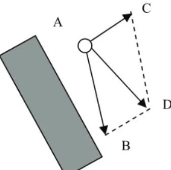
In the regular control loop of a navigation interface, a user’s mouse input (dragged vector) is translated into an offset vector for updating the next configuration of the viewpoint (AB as in the
example of Figure 2). With the influence of the virtual force field, a force vector is computed for the current configuration A and transformed into a difference vector (AC). Then this vector is
used to compose the final updating vector (AD) for the next viewpoint configuration.
3.2 Force Field Adjustment
How the static force field is applied to affect a user’s navigation is determined by the interaction with the user. In [10], the virtual force is computed dynamically according to the following for-mula. p d v user p
F
F
r
′
=
μ
×
μ
×
μ
×
r
. (1) pF
r
is the static force precomputed for a give point p whileF′
r
pis the force adjusted according to user interaction and control history. The adjustment parameters,μ
user,μv, and μd, are defined as follows.μ
v=
kv
, whereμ
vis the velocity parameter, v is themagnitude of the current velocity, and k is a constant.
1 − × = n d n d
η
μ
μ
, where n dμ
is the directional parameter for step n, andη
is determined by the dot product of Frp and the forwardFigure 1. Example of how to compute the virtual force for a viewpoint A according to the boundary cells of nearby
obsta-cles.
Figure 2. Incorporating virtual force into a control loop. A
C A
D B
facing vector. When the dot product is greater than zero,
η
=m, where m is a magnifying factor greater than 1. When the dot product is less than or equal to zero,η
=n, where n is a shrink-ing factor less than 1.μ
user=
l
is a user-preference factor speci-fied by the user. The greater value ofμ
user means stronger force influence.In [10], (l, k, m, n) are four fixed control parameters, called
pa-rameter configuration, that are determined by empirical means.
However, it was reported that the improvement of navigation efficiency with such assisting mechanisms is greatly affected by scene variations and user characteristics. There is no single pa-rameter configuration that is the best for everyone. Even if we want to find a good configuration for most people, tedious ex-periments need to be done. Therefore, it is highly desirable to have an automatic mechanism to find the best parameter configu-ration for applying virtual forces to a given user.
4. DESIGNING ADJUSTABLE VIRTUAL
FORCES
According to the experience of the above experiments, we know that the virtual force needs to be adaptive to a user in order to achieve the best improvement. Hence, we have designed two assisting mechanisms, simulation experiments and dynamic
ad-justment, which can be used to find the best parameter
configura-tion in an off-line and on-line manner, respectively. The overall system architecture proposed in this paper is shown in Figure 3. The inputs to the system could be from a real user or from simu-lated data. The intention analysis and correction module is used to modify the simulated inputs so that the user’s high level intention is kept. The parameter configuration generator is used to come up with a good configuration according to the simulation result. Then the virtual force assisting module uses this parameter configura-tion to compute the virtual force for updating the next viewpoint location.
The simulation experiment method aims to search for the best parameter configuration for a user in a specific world in an off-line manner. We first ask the user to navigate through the world by accomplish a given task and record how the user controls the interface interactively under the influence of virtual force. We then try to simulate the user’s input in an off-line manner by feed-ing the sampled input commands to the interface. In each simula-tion experiment, we use a fixed parameter configurasimula-tion for the whole course and record the number of steps taken to reach the goal location. The optimal parameter configuration can be found after all possible configurations have been exhaustively tested. The dynamic adjustment method is an on-line version of the simu-lation experiment. The main difference is that the scale is smaller in order to make it feasible for on-line applications. In this mecha-nism, the simulation experiment is done only for a segment of a few steps in the past control inputs. A greedy algorithm is used, and only neighboring parameter configurations are evaluated to find a better configuration for the next step. Although we only move the parameter configuration one step at a time, the configu-ration will converge to the best value gradually after a few steps if there exists a unique optimal one.
We will describe the above two methods in more details in the next two sections and compare the effectiveness of the two meth-ods in Section 7.
5. SIMULATION EXPERIMENT METHOD
5.1 Recording Navigation Process
From [10] we know that the virtual force field mechanism can improve navigation efficient by reducing the number of steps taken to reach the goal from a given initial location. However, in order to understand how the virtual force helps in various occa-sions, we have to record the input commands during navigation and analyze how the virtual forces are computed for these inputs. In order to record the user inputs, we have implemented an
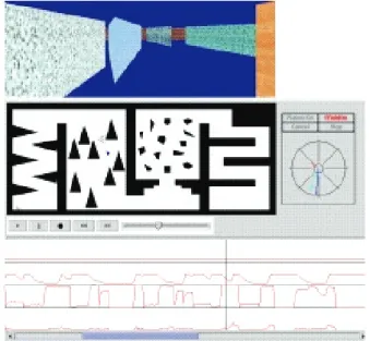
inter-Figure 3. Overall system architecture. Figure 4. Graphical interface of the experiments. The upper part is the 3D display module while the middle portion is the 2D layout map. The lower portion shows the trending of the
virtual force. Parameter Con-figuration Source of Simulation Inputs 3D Interface Virtual Force Assisting Module 3D Display Real User Parameter Configura-tion Generator Simulation Result Sampled Input Commands Intention Analysis and Correction
face, as shown in Figure 4, to collect a user’s inputs (dragged vectors) as well as the navigation trajectory under the influence of virtual forces. With this raw data, the user’s navigation process can be simulated and reproduced.
5.2 Simulation Experiment
The effectiveness of the virtual force mechanism is determined by the four-parameter configuration (l, k, m, n), and it differs greatly among users. We aim to find a personalized configuration provid-ing an optimal navigation performance for a given user. However, we do not want the user to repeat the navigation experiment in person on the other hand. In fact, a user’s interface control behav-ior might change when a user gets familiar with a specific scene. Therefore, we propose to use simulation to repeat the experiments to search for the optimal configuration. By optimal configuration, we mean the parameter configuration that can produce the virtual forces to assist the user to take the least number of steps to reach the goal location.
5.3 Intention Analysis and Input Correction
Since we have recorded the original input commands (dragged vectors) on the interactive interface, we can play back the naviga-tion if all parameters remain the same. However, once we start to modify the parameter configuration, we are altering the virtual force applied to the interaction and the resulting path might not be the same as the original one. In a real experiment, a user can ad-just the mouse input with visual feedback when the influence of virtual forces changes. However, in a simulation, if we keep the original inputs, the simulation might not generate productive or even useful movements. Instead, what we have to keep is the high-level intention behind the user’s input. Therefore, we pro-pose two methods, called milestone and directional curve, to ad-just the input command dynamically according to the current viewpoint location.
The first method creates milestones along the path by sampling points that the user passes through in the real navigation experi-ment. The milestones divide the input commands into segments. We assume that these milestones are the mid-term goals in each segment listed in sequence that reflect the user’s high-level inten-tion. During the simulation, if the closest milestone is changed to one in a future segment, then all input commands in this segment are skipped. For example, in Figure 5, when the input commands are still in the segment around milestone A and the viewpoint has
been moved to location D, which is closer to milestone C than to milestone B. In this case, all input commands behind milestone C will be skipped and next command will start in the segment con-taining milestone C.
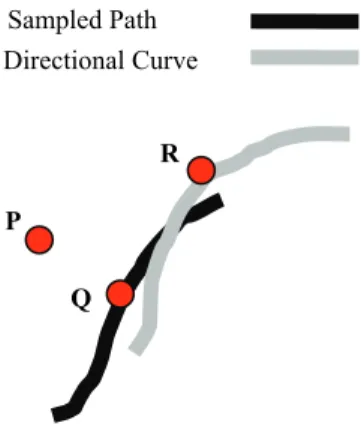
The second method, called directional curve, is designed to fix the orientation problem of the input commands. When the viewpoint location deviates from the original path due to different virtual force influence, the input commands also need to be adjusted to make the viewpoint move toward the right direction. When a user navigates, he/she controls the interface according to the scene in front of his/her viewpoint. One can imagine that there exists a short-term goal point in front of each viewpoint location. We call the list of virtual points along the path the directional curve. We can use the points along this curve to adjust the moving direction of the viewpoint. For example, in Figure 6, we assume that the current viewpoint location is at P while the closest point along the sampled path is Q. Assume that the corresponding point on the directional curve for Q is point R. Then the vector PR becomes the adjusted direction for the viewpoint. In other words, we are using an imaginary point in front of the viewpoint along the navi-gation path to guide the viewpoint movement in the simulation experiments.
The low-level input commands are almost meaningless and can-not be used in simulation if it lacks the intention behind them. The two methods above are designed to maintain the high-level inten-tion of a human user in the simulainten-tion by analyzing the navigainten-tion path traced by the user. As we will show in later sections, the simulation experiments can run by itself with these two methods even if the virtual forces vary significantly.
6. DYNAMIC ADJUSTMENT METHOD
Although the simulation experiments can find the optimal pa-rameter configuration automatically, it can only be done in an off-line manner due to the time-consuming simulation process. For example, if we divide the range of each parameter into K intervals, the total number of simulation experiments need to be done is K4
before we can find the optimal one in a brute-force search. In addition, the optimal configuration may only be good for a spe-cific scene even though it is likely to be a good starting point for the user. Consequently, we investigate the possibility of bringing
B D A C LandMark InputData A B C
Figure 5. Using milestones to modify the short-term goal for simulation experiments. When the viewpoint moves from A to
D, the simulation might skip milestone B due to a closer
mile-stone C. Figure 6. Using directional curve to modify orientation for simulation experiments.
Sampled Path Directional Curve
P
R
the experiments on-line with a smaller scale. This method is called the dynamic adjustment method.
6.1 Window sampling for on-line search
In the dynamic adjustment method, we use a sliding window of size N and maintain the input commands for the latest N steps. For example, assume that the user has taken K steps, and the system will record the command inputs for the N steps between
MAX(K-N+1, 0) and K. The system will use the last N steps to run the
simulation experiment and try to obtain a better configuration, if exists, among the neighbors for the next step. In other words, we will simulate the last N steps with different sets of parameters to see which one takes the least number of steps to reach a goal if it were used. For example, assume that the parameter configuration is denoted by (A1, A2, A3, A4). Then the neighboring
configura-tions will be (A1- Δ1, A2, A3 , A4), (A1+ Δ1, A2 , A3, A4), (A1 , A2
Δ2 , A3 , A4),…,(A1 , A2 , A3 , A4+ Δ4). The best neighbor will be
selected as the configuration for the next step. The configuration will converge to a local optimal one (if not global) gradually if the user keeps his/her navigation habits. Since the parameters are not specifically designed for a scene, the system should be able to adjust the configuration to a better one for any scenes in an on-line manner. In addition, when a user gets familiar with a scene or the navigation control, the degree of assistance that the user pre-fers might also change over time.
6.2 Adding the momentum mechanism
Although the dynamic adjustment mechanism described above is able to adjust the parameters toward a better one, the user may feel inconsistent if the parameters are changed too often simply because of scene variation. If we adjust the parameters according to the frame rate, which is typically above ten frames per second, the fluctuation on the forces may be too frequent for a user to control the interface in a consistent way. Therefore, we have added an inertia mechanism into the system such that unless enough momentum has been accumulated for a specific change, the on-line system will not adjust the configuration immediately. We keep a counter for each neighbor of the current parameter configuration and increment the counter when we attempt to visit it every time. A change is actually made only if the counter has reached a predefined threshold value, say 3. In other words, unless the changes in that direction have accumulated enough momentum, we do not make the move on the parameter changes.
With such a mechanism, we can maintain a more controllable interface by avoiding frequent fluctuation on the configuration as well as the resulting virtual forces.
7. EXPERIMENTS AND DISCUSSIONS
We have implemented the aforementioned virtual force adjust-ment mechanism in Java and integrated it into the 3D VRML [15] browser implemented by Blaxxun [1].
7.1 Effects of Using Intention Analysis
A key function in the simulation experiments is the intention analysis mechanism. In order to verify the effect of the intention analysis methods, we have done some experiments on the scene shown in Figure 7. The scene is kept simple intentionally in order to screen out other factors. In three simulation experiments with different parameter configurations, the viewpoint all gets stuck at the corner when no intention analysis and adjustment are used. On the other hand, if the intention analysis mechanism is used, the viewpoint can successfully reach the goal at the other end of the U-shaped hallway in all experiments. This shows that the high-level intention analysis is crucial for making the simulation feasi-ble.
7.2 Comparisons of Simulation Experiments
and Dynamic Adjustment Methods
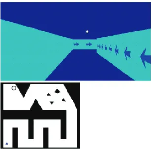
Ten subjects are invited to do the experiment of comparing navi-gation efficiencies under different assisting mechanisms. Two of them (users A and B) are familiar with the control interface of VRML browsers while another two subjects (C and D) are famil-iar with 3D game controls. Three of the subjects (E, F, and G) have a good command of computers but not 3D interfaces. An-other two subjects (H and J) only use computers occasionally (once a month) and the last one (I) never uses computers. We used the scene shown in Figure 8 for each subject to do the ex-periments with the assisting mechanisms of simulation experi-ments and dynamic adjustment.
In the simulation experiments, we first record the user’s input commands without any assisting mechanisms. Then we ask the
Figure 7. Simple experimental scene for testing the effective-ness of intention analysis.
Figure 8. The 3D scene used in the navigation experiments. The circle on 2D map is the goal location.
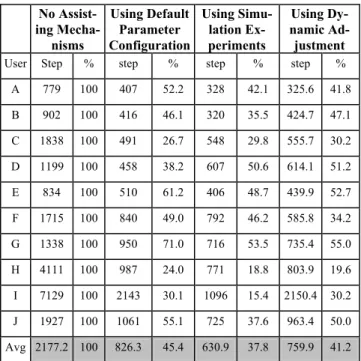
user to do two runs for each of the following two parameter con-figurations. One is the default parameter configuration, and the other one is the optimal configuration found for the user in the simulation experiments. We record the numbers of steps taken to reach the goal in each run and compute their average for each configuration. The experimental results are summarized in first three columns in Table 1. The number of steps of the runs without any assistance is used as a base (100%) to compare with other mechanisms. The second column shows the numbers of steps with the default configuration chosen carefully while the third column shows the performance with the optimal configuration. From these data, we have verified the effectiveness of using virtual force field as the assisting mechanism because the average num-ber of steps is reduced to 45.4% with the default set of parameters. We also found that the performance can be further improved by 8% if we use the optimal configuration found in simulation ex-periments. This effect seems to be more significant for novice users such as subject I, whose number of steps is reduced by around 15% if the optimal configuration is used.
In the experiment of dynamic adjustment, we choose three initial configurations for each subject to run. For each of the three initial configurations, we ask the subject to repeat the navigation ex-periments three times and take the average of the night experi-ments at the end. The result is shown in the fourth column in Ta-ble 1. We do not expect the performance of the dynamic adjust-ment mechanism to be better than simulation experiadjust-ments since its advantages are on the on-line characteristic and flexibility to adapt to the world. We found that the numbers of steps for four users (A, C, D, and H) are almost the same as the ones using the optimal configuration. One of them (Subject F) even has better performance with the dynamic adjustment mechanism.
In order to compare user discrepancy on the optimal configuration, we have chosen two subjects (A and H) to do the comparisons. Each subject is asked to run the experiments with the optimal
configuration for the other subject. For example, user A is asked to run the optimal configuration for user H and vice versa. The result is shown in Figure 9. We found that the sensitivity of each user to the virtual force configuration might vary significantly. For novice users such as user H, using other people optimal configuration might be even worse than using the default configu-ration. Therefore, we can conclude that user discrepancy does exist in adopting the assisting mechanisms and the adaptive inter-face can greatly benefit novice users in providing just-in-time navigation assistance.
8. CONCLUSION AND FUTURE WORK
In our previous work, we have shown that the assisting mecha-nism with virtual force can greatly improve navigation efficiency by reducing unnecessary collisions with environmental obstacles. However, the discrepancy between users in adopting the intelli-gent interfaces has inspired the work reported in this paper. We have designed two adaptive mechanisms to find a set of good parameters automatically for a specific user. Our experiments show that the simulation experiments can find the best virtual force parameters but the simulation can only be done in an off-line manner due to the time-consuming search process. The on-line dynamic adjustment method, on the other hand, does not require any prior analysis and could be as effective as using a fixed optimal configuration found in simulation experiments. The adaptiveness of such a mechanism to scene variations and per-sonal differences also make it attractable in more 3D applications. In order to simplify the system experiments, we only study the effectiveness of virtual forces in the current system. However, we know that the path planning method is also effective in guiding a user when a collision does happen. Therefore, in the future we will try to incorporate the automatically generated escape path into the virtual force field to make the navigation even more effi-cient. In addition to improving the navigation efficiency passively by providing virtual forces for a given scene, we are also working in the direction of redesigning a virtual scene with a better layout or more informative direction signs at appropriate places. We believe that a good assisting mechanism on a well designed scene
Table 1. The number of steps taken to reach the goal location with four different mechanisms
No Assist-ing Mecha-nisms Using Default Parameter Configuration Using Simu-lation Ex-periments Using Dy-namic Ad-justment
User Step % step % step % step %
A 779 100 407 52.2 328 42.1 325.6 41.8 B 902 100 416 46.1 320 35.5 424.7 47.1 C 1838 100 491 26.7 548 29.8 555.7 30.2 D 1199 100 458 38.2 607 50.6 614.1 51.2 E 834 100 510 61.2 406 48.7 439.9 52.7 F 1715 100 840 49.0 792 46.2 585.8 34.2 G 1338 100 950 71.0 716 53.5 735.4 55.0 H 4111 100 987 24.0 771 18.8 803.9 19.6 I 7129 100 2143 30.1 1096 15.4 2150.4 30.2 J 1927 100 1061 55.1 725 37.6 963.4 50.0 Avg 2177.2 100 826.3 45.4 630.9 37.8 759.9 41.2
Figure 9. Comparing the effects of different parameter con-figurations on different users
will provide an efficient and pleasant navigation for general way finding.
9. ACKNOWLEDGEMENT
This work was partially supported by grants from National Sci-ence Council under contracts NSC 91-2213-E-004-005 and NSC 91-2815-C-004-001-E.
10. REFERENCES
[1] Blaxxun3D. An embedding java applet VRML browser. Available at http://www.blaxxun.com.
[2] Chen, Mountford, and Sellen. A Study in Interactive 3D Rotation Using 2D Control Devices, Computer Graphics, 22(4):121-128. 1988.
[3] Drucker, S. M. and Zeltzer, D., Intelligent Camera Control in a Virtual Environment, Graphics Interface’94, 190-199. 1994.
[4] Edwards, J. and Hand, C. Maps: Movement and planning support for navigation in an immersive vrml browser. In
Pro-ceedings of VRML'97 Conference. 1997.
[5] Egbert, P. K., and Winkler, S. H. Collision-Free Object Movement Using Vector Fields. IEEE Computer Graphics
and Applications, 16(4):18-24, July, 1996.
[6] Hong, L., Muraki, S., Kaufman, A., Bartz, D. and He, T. Virtual Voyage: Interactive Navigation in the Human Colon. In Proceedings of SIGGRAPH’97 Conference, 27-35. 1997. [7] Jung. M. R., Paik, D., and Kim, D. A Camera Control
Inter-face Based on the Visualization of Subspaces of the 6D Mo-tion Space of the Camera. In Proceedings of IEEE Pacific
Graphics’98. 1998.
[8] Latombe, J.-C., Robot Motion Planning, Kluwer Academic Publisher, Boston, MA, 1991.
[9] Lenzmann, B., Wachsmuth, I. A User Adaptive Interface Agency for Interaction with a Virtual Environment. In
Work-ing Notes of the IJCAI-95 Workshop on Adaptation and Learning in Multiagent Systems, 43-46. AAAI Press, 1995.
[10] Li, T.Y., Chou, H.C. Improving Navigation Efficiency with Artificial Force Field. In Proceedings of 2001 14th IPPR
Conference on Computer Vision, Graphics, and Image Proc-essing, Taiwan, 2001.
[11] Li, T.Y., and Ting, H.K. An Intelligent User Interface with Motion Planning for 3D Navigation. In Proceedings of the
IEEE Virtual Reality 2000 Conference, 177-184. New Jersey,
2000.
[12] Maybury, M. and Wahster, W. (eds), Readings in Intelligent
User Interfaces, Morgan Kaufmann: Menlo Park, CA.
[13] Neilson, and Olsen. Direct Manipulation Techniques for3D Objects Using 2D Locator Devices. In Proceedings of the
1986 Workshop on Interactive 3D Graphics, 175-182. 1986.
[14] Tan, Desney S., Robertson, George G., and Czerwinski, M. Exploring 3D Navigation: Combining Speed-coupled Flying with Orbiting. In Proceedings of the SIGCHI Conference on
Human Factors in Computing Systems, March 2001.
[15] VRML97 International Standard, URL:
http://www.web3d.org/technicalinfo/specifications/specificat ions.htm
[16] Wernert, Eric A. and Hanson, A. J. A Framework for As-sisted Exploration with Collaboration. In Proceedings of
IEEE Visualization'99. San Francisco, October 1999.
[17] Xiao, D. and Hubbold, R. Navigation Guided by Artificial Force Fields. In Proceedings of the ACM CHI’98 Conference, 179-186, 1998.