行政院國家科學委員會專題研究計畫 成果報告
以回聲資訊隱藏為基礎的音訊浮水印技術設計(III)
計畫類別: 個別型計畫
計畫編號: NSC93-2213-E-009-066-
執行期間: 93 年 08 月 01 日至 94 年 07 月 31 日
執行單位: 國立交通大學資訊工程研究所
計畫主持人: 劉啟民
計畫參與人員: 許瀚文,楊宗瀚等
報告類型: 精簡報告
報告附件: 出席國際會議研究心得報告及發表論文
處理方式: 本計畫可公開查詢
中 華 民 國 95 年 7 月 24 日
行政院國家科學委員會補助專題研究計畫成果報告
※※※※※※※※※※※※※※※※※※※※※※※※※
※ ※
※
以回聲資訊隱藏為基礎的音訊浮水印技術設計(III)
※
※ ※
※※※※※※※※※※※※※※※※※※※※※※※※※
計畫類別:■個別型計畫 □整合型計畫
計畫編號:
93-2213-E-009-066
執行期間:
93 年 8 月 1 日至 94 年 7 月 31 日
計畫主持人:劉 啟 民 教 授
共同主持人:
本成果報告包括以下應繳交之附件:
□赴國外出差或研習心得報告一份
□赴大陸地區出差或研習心得報告一份
□出席國際學術會議心得報告及發表之論文各一份
□國際合作研究計畫國外研究報告書一份
執行單位:
交
通 大 學 資 訊 工 程 系
中 華 民 國
95 年 7 月 20 日
以回聲資訊隱藏為基礎的音訊浮水印技術設計(III)
計畫編號:
93-2213-E-009-066
執行期限:民 國 9 4 3 年 8 月 1 日 起 至 民 國 9 5 年 7 月 3 1 日 止 主持人:劉啟民 交通大學資訊工程系 主要參與研究生:許瀚文,楊宗瀚 一、中文摘要 上年度研究進度報告和本年度研究重點 本計畫第一年目標為系統設計,包含以下目標 z 理論分析。 z 系統參數確定以保證音訊品質不遭破壞。 z 系統的程式設計。 z 分析何種音樂特色可加入不影響音樂品質和資 料抓取 z 可加入浮水印資料量分析。 z 不可加入浮水印音樂片段偵測。 本計畫第二年目標為系統改進和新方法,包含以下目 標 z 靜音的偵測處理。 z 高浮水印偵測率方法。 z 提出提高浮水印資料量方法。 z 音樂品質評估方法。 z 浮水印資料對壓縮方法的強健性分析。 z 浮水印資料對音效處理方法的強健性分析。 本計畫第三年目標為進行大量實驗來探討 z 音樂品質評估方法。 z 浮水印資料對壓縮方法的強健性分析。 z 浮水印資料對音效處理方法的強健性分析。 現本計劃已完成。 Abstract
This report illustrates the backgrounds of the project in Chapter 1 and provides the research results in the first two years in Chapters 2 and 3. In Chapter 4, we give some experiments we have conducted.
Keywords: Watermark, Audio processing
Introduction
In the last decade, storage of most multimedia data, such as music and pictures, is no longer in analog format, but rather in digital format. For digital data, the improvements in compression techniques distinctly reduce the storage size of these multimedia files. The small size of digital audio files makes it easy to spread
music to anywhere in the world through the Internet. Due to the rapid growth of Internet traffic throughout the world over the last few years, the distribution of digital audio has become even easier. For example, nowadays, many digital audio pieces, especially the popular songs, are spreading quickly and easily over the Internet. In addition, e-commerce has allowed trade to occur on a worldwide scale. The simple access and lossless duplication of digital files have already violated the intellectual property of a myriad of original authors and producers. This violation of copyrighted material makes selling digital multimedia products, like e-books or MP3 music, via the Internet a huge risk. The lack of protection from these attacks on intellectual property over the Internet obviously increases the importance of copyright protection [1] [2].
Traditionally, the copyright is declared by putting a special trademark, like a unique type of sticker, on the products or by giving a registration card with the products. However, the traditional methods may not work well in digital world due to the easy reproduction and simple modification characteristics of the digital products. For example, some of the software, which request the user for a registration number to install or to start the program, have been attacked by hackers in order to create an unauthorized, but fully-functional copy that does not require any registration. Thus, the unauthorized software was spreading over the Internet. Software engineers are now searching for methods to avoid destruction of registration information from these types of copyright attack. Currently, the best way to defend against intensive violation of intellectual property, especially to data in digital format, is to hide the authorization information within the software or multimedia files and to make the hidden information imperceptible, which is in the concept of watermark. Some digital audio watermarking techniques were designed to protect the intellectual property of music. The basic idea of the digital audio watermark is to embed some specified information like a personal signature or serial numbers into the digital products before selling them. The watermark can help to prove the ownership of the producers and buyers, to justify the authorization of the products and to avoid the violation of intellectual properties. Thus, selling products, such as music and movies, in digital format through the Internet will no longer threaten the intellectual property [3].
1.1 Basic Concepts of Watermark
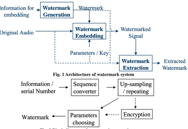
The architecture of watermark system looks like Fig. 1. The input of the watermark system is the information for embedding and the original audio; the output of the watermarking system is the watermarked signal and the extracted watermark. The watermark data is generated
separately before considering the host multimedia file, as
illustrated in Fig. 2. The format of watermark data depends on the original format of the information as well as the embedding algorithm, which is adopted the host multimedia file. The watermark is embedded into the multimedia file using specified control parameters and the private key of the technique, which generates a watermarked file as illustrated in Fig. 3 [4]. The embedding algorithm must cope with the variation of the
Watermark
Generation
Watermark
Embedding
Watermark
Extraction
Information for
embedding
Original Audio
Watermarked
Signal
Extracted
Watermark
Watermark
Parameters / Key
Watermark
Generation
Watermark
Embedding
Watermark
Extraction
Information for
embedding
Original Audio
Watermarked
Signal
Extracted
Watermark
Watermark
Parameters / Key
Fig. 1 Architecture of watermark system
Information /
serial Number
Sequence
converter
Up-sampling
/ repeating
Watermark
Parameters
Encryption
choosing
Information /
serial Number
Sequence
converter
Up-sampling
/ repeating
Watermark
Parameters
Encryption
choosing
Fig. 2 Block diagram of watermark generation
Embedding
algorithm
Original
audio signal
Watermarked
audio signal
Watermark
Key
Parameters
Perceptual
analysis
Embedding
algorithm
Original
audio signal
Watermarked
audio signal
Watermark
Key
Parameters
Perceptual
analysis
Fig. 3 Block diagram of watermark embedding
Watermark
recovery / detection
Test audio signal
Watermark or
detect result
Watermark and / or
original audio signal
Key
Parameters
Watermark
recovery / detection
Test audio signal
Watermark or
detect result
Watermark and / or
original audio signal
Key
Parameters
media data and must carefully ensure that the changed media can still be read, watched or listened without allowing other people to perceive any difference from an ordinary, non-watermarked file.
Authorities may check the embedded information by extracting the watermark within the watermarked file with some statistical techniques. As shown in Fig. 4, the extraction approach, which should approximate to the inverse of the embedding procedure, requires the same control parameters and the private key, which was used in the embedding procedure. After the hidden data has been extracted back from the watermarked audio, the authorized individuals can determine or recognize the owner of this media file [5].
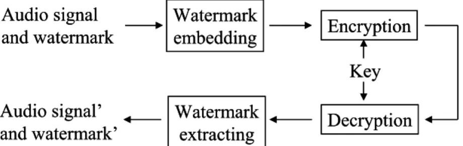
1.1.1 Cryptography and Watermark
Watermark and cryptography appear similar, but the two terms are far from the same. Cryptography and watermark are both used on the protection of some important information, and are applied into the original data that requires protection. However, cryptography is used to protect content from being access by anyone without authorization. For example, an encrypted audio file cannot be listened if the file is not decrypted first. To decrypt the encrypted data, the private key is required to transfer the data back to its original format prior to encryption. Once the data is decrypted, the data is no longer under protection and can thus be accessed by any person [6]. In contrast to cryptography, a watermarked data can be directly access by any person; there is no need to ‘un-watermark’ the data in advance. In particular, people should not be able to recognize whether the data contains an embedded watermark. This covert method is completely distinct from the cryptography approaches. For instance, one can listen to a watermarked music file without any ‘un-watermarking’ step and this person would not realize the existence of watermark. While the data is all recovered to the original format after decryption in cryptography, the watermarks are designed to permanently reside within the host data in any condition. Thus, the watermark cannot be removed from the host data even after intentional hacker attacks or repeated reproduction unless one has the private key and the watermarking algorithm has been designed as watermark removable. Some watermark techniques make the mark impossible to remove even if the private key is known; in the other words, once the watermark is added, it is indestructible.
Thus, based on the characteristics of cryptography, encryption is typically used on protecting data from being intercepted during transmission, or preventing
unauthorized access of the content. On the other hand, the watermark is generally used to protect copyright and to declare the ownership of the content [7]. The cryptography and watermark can be used together to gain better profit, and the working flow is illustrated in Fig. 5.
1.1.2 Requirements of Audio Watermark
To achieve the goal of copyright protection, an audio watermarking technique has to satisfy several requirements:
z Embedding into the audio signal
The watermark must be embedded directly into the main part of audio signal, not into the header of audio file. Information in the file header may be easily removed or manipulated, but the data embedded in the audio signal would only be destroyed when the audio itself is destroyed [8].
z Transparency in perception
The watermark should be imperceptible to human ears; otherwise, it would affect the audio quality of the watermarked signal and would consequently be detected [9].
z Information extractable
The embedded watermarks are used for ownership verification, so the watermarks must be able to be extracted or to be detected. The algorithm of watermarking technique should not only be able to embed the information but also be able to recover it.
z Recovery without referring to the original
Unless an audio signal can be proven as the original signal by a third party, there is no way to determine whether or not an audio piece is the original. Anyone may generate a fake original, which can extract a different but valid watermark with the watermarked audio piece. Due to the possibility of counterfeit originals, the watermark extracting techniques that depend on the original audio signal are not reliable [10].
z Robustness
Digital data are easily modified and manipulated using computers and widely available software packages. Several frequently used programs with lossy signal processing functions may be used to modify the watermarked digital audio. Furthermore, a third party may attempt to modify the watermarked signal in order to destroy the embedded data by attacking the file with multiple kinds of audio process operations. A watermarking procedure should be robust to withstand signal manipulation and processing operations on the host data; for example, up/down-sampling, compression, noise, A/D-D/A (A: analog, D: digital) conversions,
Audio signal
and watermark
Watermark
embedding
Watermark
extracting
Audio signal’
and watermark’
Encryption
Decryption
Key
Audio signal
and watermark
Watermark
embedding
Watermark
extracting
Audio signal’
and watermark’
Encryption
Decryption
Key
etc [11]. z Security
The watermark embedding procedure must be secure. An unauthorized user must not be able to extract the watermark or even to detect the presence of the embedded data. A watermarking scheme is truly secure if knowledge of the exaction algorithm for embedding the data does not help an unauthorized party to detect the presence of the embedded data. This security standard is analogous to the criterion for measuring the security of an encryption method. For further security, the watermark may be encrypted before its insertion into a host signal [8].
z Support of multiple watermarks
An embedding algorithm allowing multiple watermarks to co-exist is more preferable. In some circumstances, it is desirable to embed multiple watermarks into the same host signal, for example, one for the producer and one for the buyer [9].
1.2 Audio Watermarking Techniques
Hiding data in audio signals presents a variety of challenges, due in part to the wide dynamic and differential range of the human auditory system (HAS) as compared to the other senses. The HAS perceives over a range of powers greater than one billion to one and a range of frequencies greater than one thousand to one. Although the human auditory system is sensitive, there are some ‘spaces’ available in the perception range where data may be hidden. While the HAS has a large dynamic range, it often has a fairly small differential range. For instance, loud sounds tend to mask out the quiet ones nearby. Additionally, while the HAS is sensitive to amplitude and relative phase, it is unable to perceive absolute phase. Finally, there are some environmental distortions that commonly occur and are typically ignored by the listeners in most cases [12].
1.2.1 Main Techniques
Information hiding techniques receives more and more attention from the research community and from the industry in recent years, as Table 1 shows the main driving force is concern over copyright protection [7]. However, most of the works are focused on watermarking techniques of image and video, and only a few audio data
hiding schemes have been proposed. This indicates that the amount of information that can be embedded robustly and inaudibly is much lower for audio media than for visual media. An additional problem in audio watermarking is that the HAS is much more sensitive than HVS (human visual system), and that inaudibility of audio is much more difficult to achieve than invisibility
of images [13].
Based on different types of ‘spaces’ for information hiding, several kinds of watermark approaches have been proposed in recent years:
z Low-bit coding
The first type embeds watermark by replacing the least significant bit (LSB). In low-bit coding technique, watermark data is transferred into a binary stream and the stream is used to replace in series the LSB of each audio sample. This technique may introduce some noise and the embedded watermark is easy to be destroyed [14]. This technique may also be implemented over the frequency domain [16].
z Region-based coding
The second type embeds watermark in some frequency regions of the audio signals. This approach embeds the watermarks into some perceptually insignificant regions, such as the high frequency region, so that the watermark is inaudible. The concentration of hidden information in a small region makes this approach less robust [9].
z Phase coding
The third type embeds the watermark in the Fourier transform phase coefficient. Human ears are relatively insensitive to phase distortions, especially the absolute phase value. A phase coding scheme was proposed to update the phase of an initial audio segment and keep the relative phase of following segments unchanged [14]. z Embedding during compression
Some methods combine watermark embedding with the compression or modulation processes, such as during the vector quantization step in compression procedure [17]. z Pseudo-noise coding
Most techniques add the watermark as pseudo-random noise, some of which are generated based on the spread spectrum concept, in the time domain. Since human ears have different sensitivity to additive noise in different frequency bands, most of the proposed methods in this area use some type of filter to shape the added pseudo-random noise and achieve inaudibility [9] [19]. z Echo data hiding
Still, some approaches embed the watermark as the echo signals of the original audio. The inaudibility of echo data hiding is based on temporal masking effect of the human auditory system. Based on HAS, if the echo is added within a certain range, the human ears cannot distinguish it from the original. The echo is perceived as resonance in our environment. The watermark signals are actually
delayed and attenuated versions of the original audio signals in this kind of approaches [12].
1.2.2 Advantages of Echo Data Hiding
Each approach mentioned above has its own pros and cons. The low-bit coding technique is not robust;
Table 1 Number of publications on digital watermarking in the past few years
Reference: [15]
Year 1992 1993 1994 1995 1996 1997 1998
although this technique provides the highest information transmission rate, the embedded watermark is very fragile. The phase coding approach provides much better robustness, but has a very low information transmission rate since the secret information is encoded only in the first signal segment [18]. The method that embeds the watermark during the compression procedure cannot survive when another kind of audio file format is used. Moreover, embedding the watermark within compression processes is also dependent on compression software produced by particular company. In the algorithm, which hides data in perceptually insignificant regions, the watermark may be easily destroyed when audio compression is performed, especially for low bit rate compression, where the least significant parts of the audio are the first to be removed [9]. One of the most common approaches for hiding data in audio is to introduce the information as additive noise. The main drawback for these noise-adding approaches is that lossy data compression algorithms tend to remove most imperceptible artifacts, including typical low dB noise, and the embedded data would be removed at the same time [12]. Echo data hiding introduces changes to the host audio, which has the characteristic of environmental conditions rather than random noise, thus it is more robust even through any general lossy data compression. However, the available rate to transmit information is a little low in echo data hiding, as compared to some of the other approaches[14] [18].
Based on the tradeoffs between robustness and
information transmission rate of watermarks, the echo data hiding technique is the fittest method and will be further studied in this report.
1.3 Design Issues
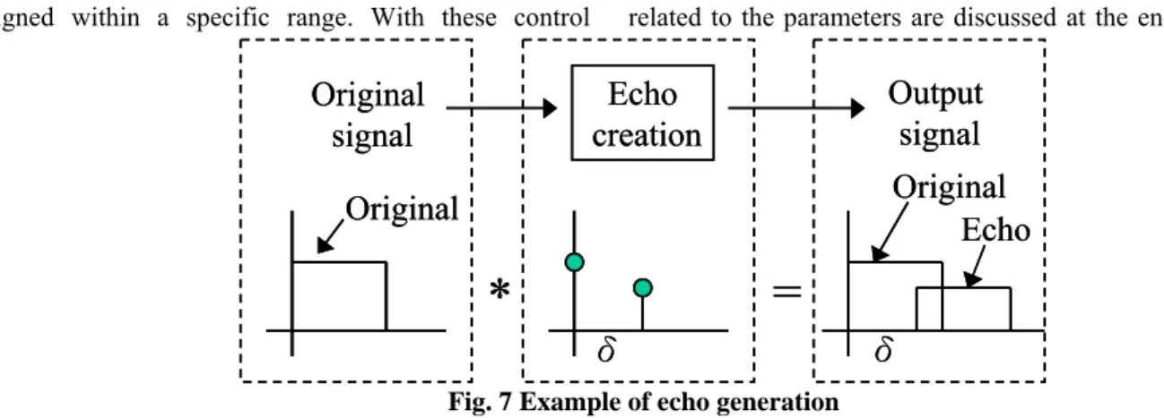
There are four main procedures for echo data hiding technique: the watermark data generation, the echo creation, the watermark embedding and the watermark extraction, as illustrated in Fig. 6.
In the first stage, the information converting to the embedding watermark must be chosen, and the format of the watermark data, for example a binary stream, must be decided. The embedding information is then converted to the predefined format as the watermark file. The watermark format helps to decide the amount of information can be embedded in per block of the audio signal. For instance, if a binary stream is generated, one single bit is hidden in each block. Different watermark formats may employ different number of digits to encode the information data, which will be embedded into one single block.
In the echo creation stage, the delay values need to be chosen in a specified proper range. The echo signal is then created from a combination of several delay signals. The transition function used for combining the delay signals will influence the audio properties and the extraction accuracy.
During the watermark embedding stage, the embedding control parameters, such as the magnitude of the echo and the embedding rate of the watermark, are
Table 2 Characteristics of watermarking techniques
Reference: [14] [18] Time / frequency domain embedding
Additive
noise? Robustness Techniques
Yes Bad Low-bit coding
Yes Middle Pseudo-noise coding
Time domain
No Good Echo data hiding
Yes Bad Region-based coding
Frequency domain
No Good Phase coding
Time / frequency Embedding during compression
Watermark Generation Echo Creation Watermark Embedding Watermark Extraction Information Format
Delays TransitionFunction
Magnitude EmbeddingRate Watermark Generation Echo Creation Watermark Embedding Watermark Extraction Information Format
Delays TransitionFunction
Magnitude EmbeddingRate
assigned within a specific range. With these control
parameters, the echo is embedded into the original audio signal, and then the audio signal becomes an intellectual property protected file. For each audio signal, some of the segments are unsuitable for hiding data since the watermark added in these segments could not be correctly extracted and would decrease the overall watermark recovery accuracy. Also, the block size for watermark embedding is limited by the accuracy rate. There is a tradeoff between the watermark embedding rate and the recovery accuracy rate.
To examine the embedded information within the multimedia file, the extraction stage is needed. The algorithm of watermark extraction in echo data hiding technique is based on the autocorrelation characteristics of the original audio signal and the watermark echo signals. The extraction requires the control parameters, like the delay values and the watermark-embedding rate, as the inputs to check the echo existence of the extraction algorithm. The detection result is later converted into the same format as the watermark information source. The converted value may be compared with the source of embedded data to check the ownership of the audio piece.
Chapter 2 System Design
For the protection of intellectual property, every audio watermarking technique embeds the information into the host audio signal based on some consideration of perceptual characteristics of the human auditory system. To extract the embedded data from the host audio pieces, some statistical approaches were used [20].
Based on the tradeoff between robustness and watermark-embedding rate, a watermarking system for audio signal based on echo data hiding techniques is chosen for study. The echo data hiding techniques employ the temporal masking characteristics of audio combined with imitation of a natural environmental echo to embed the watermark data into the host audio. A statistical method of calculating the autocorrelation of the watermarked signal is used to extract the embedded information.
This chapter begins by explaining several basic concepts used in echo data hiding approach. The following sections discuss each step of the echo data hiding procedure and the corresponding parameters in detail. Based on the different combinations of the control parameters in the procedure, some basic assumptions
related to the parameters are discussed at the end of this
chapter. Finally, the performances of the echo data hiding system with various control parameters are illustrated for comparison.
2.1 Concepts of Echo Data Hiding
In the echo data hiding technique, we introduce an echo signal into the audio in order to hide the watermark information. The temporal masking property of audio and the simulated echoes are used in watermark embedding, and the statistical method of autocorrelation is used for hidden information extraction [12].
2.1.1 Echo
The definition of ‘echo’ is: “a sound heard again near its source after being reflected” or “a repetition of sound produced by the reflection of sound waves from a wall, mountain, or other obstructing surface” [21]. An echo is, in fact, a natural phenomenon of sound, which is a kind of repeat of the original. When people play music, echoes occur in the room when the sound wave is reflected from the walls or off other objects. People seldom notice the occurrence of echoes in our environment just because they are already accustomed to the existence of echoes. Now a simulation of this natural phenomenon is used for hiding the specific information within an audio signal. To simulate the effect of natural echoes in the original audio, the echo signals are created and embedded directly into the original signal. For example, the echo can be created with a delay time δ and an echo amplitude decay A, as shown in Fig. 7. Thus the echo signal is combined with the original and becomes single one output signal.
2.1.2 Temporal Masking
Watermarks in audio signals are embedded in the positions where human perception would not be able to detect, while the receiver of audio is without doubt the human ear. Through the characterization of human auditory perceptual system, particularly the time-frequency analysis of the capabilities of the inner ear, watermark finds its place to hide in the audio signal. Within the temporal masking effects of audio, the echo data hiding technique conceals the watermark from being heard.
δ
*
=
Original
Echo
δ
Original
signal
Echo
creation
Output
signal
Original
δ
*
=
Original
Echo
δ
Original
signal
Echo
creation
Output
signal
Original
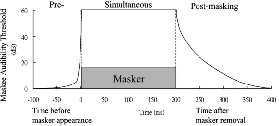
The masking phenomena of auditory perception extend in time beyond the window of simultaneous stimulus presentation. In other words, for a masker of finite duration, temporal masking occurs both prior to the masker appearance as well as after the masker removal. Fig. 8 schematically presents the skirts on both sides of the masker. The absolute audibility thresholds for masked sound increase exponentially prior to the occurrence of the masking signal and decrease exponentially posterior to the removal of the masker. While significant pre-masking tends to last only about 1-2 milliseconds, post-masking would extend anywhere from 50 to 300 milliseconds, depending on the strength and duration of the masker. As shown in Fig. 8, the pre-masking decays much more rapidly than the post-masking, so the spotlight of echo data hiding is concentrated on the post-masking region [22] [23].
2.1.3 Autocorrelation
Within a series of audio signals, the echoes appear to be the repetitive signals of the audio that were just played. To determine whether a sequence of signals is in some degree self-repeating, the calculation of its autocorrelation is usually adopted. The autocorrelation of a given signal x(n) is defined as
∑
+∞ −∞ =+
=
m xxn
x
n
m
x
m
R
(
)
(
)
(
)
. (1)Let k = n+m and thus m = k–n. By replacing m in Eq. (1),
the autocorrelation can be equally defined as
∑
+∞ −∞ =−
=
k xxn
x
k
x
k
n
R
(
)
(
)
(
)
. (2)For each position k in the time domain, Eq. (2) can be used to calculate the corresponding autocorrelation value. When an echo exists at time k1, the autocorrelation
value for the signal that has a time offset of k1 would be
larger than the autocorrelation value for any other signals with an offset of k (where k≠k1). By determining the
maximum autocorrelation value, the embedded echo can be detected. Thus, if any echo was hidden in the audio signals, the autocorrelation can help to detect the offset of the echo at any time. Obviously, if any specific information was hidden inside the audio with echoes, the autocorrelation is helpful for deriving the information and the embedded data in the audio can then be extracted [12].
2.2 Echo Data Hiding System Design
The watermarking system based on echo data hiding is explained in this section. The echo data hiding system can be divided into the following four stages: (1) the watermark data generation; (2) the watermark embedding; (3) the watermark extraction; (4) the check of recovery accuracy. A simple block diagram of the system is illustrated in Fig. 9. Time before masker appearance Time after masker removal 0 20 40 60 -100 -50 0 50 100 150 200 250 300 350 400 Time (ms) (d B )
Pre-
Simultaneous
Post-masking
Masker
Maskee Audi bili ty T hreshold Time before masker appearance Time after masker removal 0 20 40 60 -100 -50 0 50 100 150 200 250 300 350 400 Time (ms) (d B )Pre-
Simultaneous
Post-masking
Masker
Maskee Audi bili ty T hresholdFig. 8 Temporal masking properties of the human ear
Binary Watermark Generation Echo Watermark Embedding Echo Watermark Extraction Information for Embedding S(n) S’(n) W’(m) W(m) Recovery Accuracy Check Comparison Result Binary Watermark Generation Echo Watermark Embedding Echo Watermark Extraction Information for Embedding S(n) S’(n) W’(m) W(m) Recovery Accuracy Check Comparison Result
2.2.1 Watermark Data Generation
As Fig. 10 shows, watermark data generation involves picking up the data, which is going to be embedded into the host audio, and converting this data into the predefined format of the watermark, where the format is usually a binary stream. For example, a text string “Hello” is converted into the output binary stream as “0100100001100101011011000110110001101111”; or the data of a graph such as Fig. 11 is converted into the
output binary stream as “01000111010010010100011000111000 ……”. Converting any data into a binary stream is quite simple,
since all of the data is in fact presented as binary code inside the computer. If other watermark formats are adopted, the associated algorithm used in the ‘watermark conversion’ block should be changed. Moreover, the format of the watermark specifically depends on the watermark embedding method adopted. For example, if the embedding algorithm allows some empty segment without any data to be embedded, the converted binary sequence may become “0100 0111 010 01 000 ……”, in which the blank means no watermark bit is hidden in that block. Thus, watermark data generation is pretty simple and corresponds with the binary representation within the computer.
2.2.2 Echo Watermark Embedding
The goal of echo watermark embedding is to create the watermarked audio, which may be distinguished from the original audio by a slight difference, but should not be identified. That is, the audio quality of the
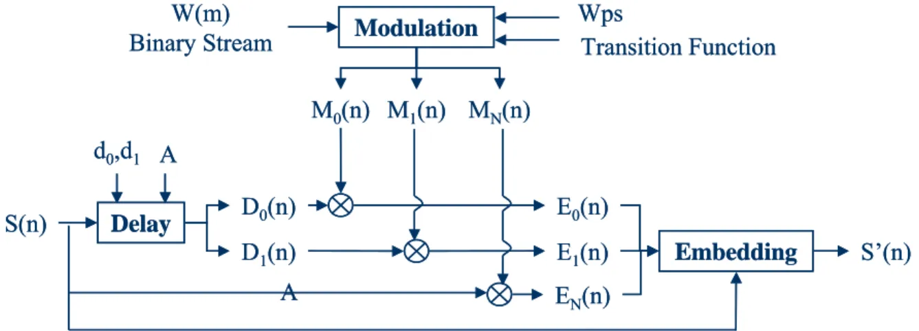
watermarked audio must be kept the same as the original audio. The embedding procedure of the echo watermark basically includes two modules: the echo creation stage and the watermark embedding stage as shown in Fig. 6. With the host signals, the echo creation procedure generates the repetitive signals of the original. The created echoes and the inputted watermark data go through the watermark embedding modules to produce the watermarked audio signals.
In echo creation, two important parameters, which indicate the delay values, should be assigned to generate some delayed signals for the creation. Since the watermark data is a binary stream, the two delay values d0
and d1, which represents the delays of digit ‘0’ and digit
‘1’ respectively in the binary stream, need to be assigned. In addition, a decay rate ‘A’, where 0<A<1, needs to be specified for generating the echo signals as shown in Fig. 13. Assuming that S(n) indicates the host audio signal, the two delay signals using the specified magnitude and decay rate can be represented by D0(n) and D1(n) as the
following equations:
Information for
embedding
Binary stream
converter
Watermark
W(m)
Information for
embedding
Binary stream
converter
Watermark
W(m)
Fig. 10 Watermark data generation in echo data hiding systemFig. 11 Leaf
Wps
M
N(n)
S(n)
Delay
d
0,d
1D
0(n)
D
1(n)
Modulation
M
0(n) M
1(n)
A
Embedding
E
0(n)
E
1(n)
S’(n)
Transition Function
E
N(n)
A
W(m)
Binary Stream
Wps
M
N(n)
S(n)
Delay
d
0,d
1D
0(n)
D
1(n)
Modulation
M
0(n) M
1(n)
A
Embedding
E
0(n)
E
1(n)
S’(n)
Transition Function
E
N(n)
A
W(m)
Binary Stream
)
(
*
)
(
0 0n
A
S
n
d
D
=
−
(3) and)
(
*
)
(
1 1n
A
S
n
d
D
=
−
. (4)On the other side, with the given watermark data stream, the watermark is embedded into the host audio with a predefined rate, watermark per second (‘Wps’). With the rate of Wps assigned, two or three modulator streams are generated from the watermark stream in the block of modulation. The values in the modulators should be either one or zero to represent the existence of specific digits, while the values of the modulators in the transition region can be between one and zero. In the echo-watermark embedding module, the two main modulators, indicated as M0(n) and M1(n), are used to
modulate D0(n) and D1(n). When a block without watermark data is allowed, another modulator MN(n) (where N means null, symbolizing ‘non-digit’) would be adopted. With the modulators, the embedding algorithm can determine whether the specific delay signal is added into the current block. For example, if the digit ‘1’ is
hidden in the current block, the corresponding segment of the modulator M1(n) would have value one, and the other modulators M0(n) and MN(n) would have value zero. As shown in Fig. 14, the content in each block of the modulator is highly dependent on the watermark data stream. The block size is selected based on the specified watermark embedding rate and the sampling rate of the original audio, which is given by
Wps rate sampling audio original size block_ = _ _ _ . (5) At the boundaries of each block, a transition function is introduced to avoid a sudden change in magnitude of the embedding signal. The transition function for a smooth change may be either a linear or nonlinear function. For example, the equation
1
)
(
)
(
)
(
1 0n
+
M
n
+
M
n
=
M
N , (6)makes the magnitudes change linearly, whereas another equation
D
0(n)
D
1(n)
a
b
c
d
e
f
g
S(n)
d
0d
1D
0(n)
D
1(n)
a
b
c
d
e
f
g
S(n)
D
0(n)
D
1(n)
a
b
c
d
e
f
g
S(n)
d
0d
1Fig. 13 S(n) and its relationship with D0(n) and D1(n)
D
0(n)
d
0D
1(n)
d
1a
b
c
d
e
f
g
0
1
0
0
0
1
1
0
1
0
0
0
1
1
a
b
c
d
e
f
g
M
1(n)
M
0(n)
0
1
0
1
D
0(n)
d
0D
1(n)
d
1a
b
c
d
e
f
g
0
1
0
0
0
1
1
0
1
0
0
0
1
1
a
b
c
d
e
f
g
M
1(n)
M
0(n)
D
0(n)
d
0D
0(n)
d
0D
1(n)
d
1D
1(n)
d
1a
b
c
d
e
f
g
0
1
0
0
0
1
1
0
1
0
0
0
1
1
a
b
c
d
e
f
g
M
1(n)
M
0(n)
0
1
0
1
1
)
(
)
(
)
(
2 2 1 2 0n
+
M
n
+
M
n
=
M
N (7)causes the change in magnitudes of the signal to appear sinusoidal.
With the delay signals and the modulators generated, the embedding signals are generated in the following steps.
Firstly, in the ‘modulation’ block of Fig. 12, the delay signals are modulated using the modulators, and the embedding signals are generated by
)
(
*
)
(
)
(
0 0 0n
D
n
M
n
E
=
(8) and)
(
*
)
(
)
(
1 1 1n
D
n
M
n
E
=
. (9)To cope with the embedding signals within each block, in block which no watermark bit needs to be embedded, a decay of the original signal is modulated as illustrated in Fig. 12, that is,
)
(
*
)
(
*
)
(
n
A
S
n
M
n
E
N=
N . (10)Basically, each embedded bit should have magnitude one in the correlating modulator at the time except for the block boundaries condition. Thus, one of the embedding signals, E0(n), E1(n) and EN(n), has non-zero amplitude and the remaining signals are in silence. This relationship is based on the design of modulators that only the specified modulator corresponding to the embedded bit should have a magnitude of one at any time.
Secondly, the embedding signals, E0(n), E1(n) and
EN(n), together with the host signal S(n) are the inputs of
the ‘embedding’ block.
Finally, the embedding signals and the original audio are combined to generate the watermarked audio for each embedding block. In the embedding block, we first add E0(n), E1(n) and EN(n) together, which produces the combined embedding signal represented by
E(n) as in the following,
)
(
)
(
)
(
)
(
n
E
0n
E
1n
E
n
E
=
+
+
N . (11)With the combined signal E(n), a watermarked audio S’(n) is then constructed simply by adding S(n) and E(n) together as
)
(
)
(
)
(
'
n
S
n
E
n
S
=
+
. (12)Obviously, the watermarked audio signals may
have more energy than the original signals because the addition of echoes. To keep the energy of the watermarked audio signals equivalent with the original audio signals, the normalization of the watermarked audio is made to preserve the energy level of the original audio by the following equation,
2
1
)
(
)
(
)
(
'
A
n
E
n
S
n
S
+
+
=
. (13)The normalized parameter in Eq. (13) equals to the summation of squared values of the signals energy [24], which is defined as
∑
∞ −∞ ==
nn
x
E
(
)
2 . (14)Where the value one is used to represent the energy factor of the original and the value A is the energy factor of the embedding audio signal. For a given audio signal, the embedding steps can provide the watermarked audio signal, which can be used or sold as a copyright protected product.
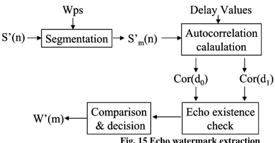
2.2.3 Watermark Extraction
Since the extraction of the watermark is done block by block, the information about the embedding rate (Wps) is required in order to segment the watermarked audio signal into blocks. To examine the existence of the specific watermark, the autocorrelation value of each block is calculated. The autocorrelation count is focused on the positions where the echo may be most probably positioned, at times d0 and d1. In this report, a normalized
version of the autocorrelation matrix in Eq. (2) is used for watermark detection. That is,
∑
∑
∞ −∞ = ∞ −∞ = − = k k xx k x k x n k x k x n R ) ( ) ( ) ( ) ( ] [ . (15)From Eq. (15), the autocorrelation count at time distance
d0 and d1 are
∑
∑
− = ) ( ' ) ( ' ) ( ' ) ( ' ) ( 0 0 n S n S d n S n S d Cor (16) andS’(n)
Segmentation
Wps
Autocorrelation
calaulation
Delay Values
Comparison
& decision
S’
m(n)
Cor(d
0)
Cor(d
1)
W’(m)
Echo existence
check
S’(n)
Segmentation
Wps
Autocorrelation
calaulation
Delay Values
Comparison
& decision
S’
m(n)
Cor(d
0)
Cor(d
1)
W’(m)
Echo existence
check
∑
∑
− = ) ( ' ) ( ' ) ( ' ) ( ' ) ( 1 1 S nS n d n S n S d Cor , (17)where n is the time index from the starting position to the end of the current block.
The resulting of the autocorrelation counts, Cor(d0)
and Cor(d1), are then used for echo existence check prior
to the extraction of the watermarked data. This check provides a threshold to determine whether or not the handling block has an echo embedded within it. When no echo exists in the current block, based on Eqs.(10), (11) and (12), the signal S’(n) is
2 2 2 2 1 ) ( ) 1 ( 1 ) ( ) ( 1 ) ( ) ( 1 ) ( ) ( ) (' A n S A A n AS n S A n E n S A n E n S n S N + + = + + = + + = + + = . (18)
Where E(n) is directly replaced by the embedding signal
EN(n), which is a function of S(n), and the signals E0(n)
and E1(n) are ignored. As shown in the Eq. (18), when no
echo exists, the watermarked signal S’(n) becomes a function of S(n) that the characteristics of S’(n) is almost the same as the original signal S(n). That is, based on the direct relationship between S’(n) and S(n) in the absence of an echo, the autocorrelation characteristic of the original signals can be used to define the threshold of echo existence check. For example, several audio streams were tested for its autocorrelation characteristic before watermark embedding, and the average results are shown in Fig. 16. Observing in Fig. 16, the curved line of the autocorrelation value passes through zero point at approximates 0.6msec. Before the crossing at 0.6msec, the curve approximates a linear line that decreases from an initial value of one. Whereas after passing through the zero point, the curve looks like a near-sine wave. The threshold of echo existence check is usually used when the delay of echo is larger than 0.7msec (this is discussed with control parameters). For the echo existence check, the threshold may be simply assigned the maximum autocorrelation value of the original signal in the segment, which at time larger than 0.7msec. For further precision of the autocorrelation value threshold, a sine function can be assigned for the threshold definition, such as
β
θ
α
+
+
=
*
sin(
t
)
Threshold B
, (19)where B is the amplitude of the sine function, α is the vibration cycle of the sine wave, β determines the shift of this autocorrelation curve, and θ defines the time offset. The parameters in Eq. (19) are in fact signal dependent. In other words, the threshold would not possess the same value when different signals are tested, but rather the parameters should be re-assigned every time based on the characteristics of the different audio pieces.
After passing the echo existence check, the blocks that have been verified as echo embedded must be further categorized to establish whether there exists a ‘zero’ echo or a ‘one’ echo. Determining the echo delay value involves a simple comparison of the autocorrelation values. The delay time, which produces the greater autocorrelation value, represents the proper echo value. For example, if Cor(d0) > Cor(d1) in a segment, then the
embedded bit is digit ‘0’ in that block, and vice versa. The steps shown in Fig. 15 are repeated block by block until all of the watermarked information has been extracted.
2.2.4 Recovery Accuracy Check
The final part of the echo watermarking procedures is to check the extracted data and to determine whether it is equivalent to the particular information by comparing these two data stream. This check is called watermark recovery accuracy check, where the recovery accuracy rate is defined as % 100 * _ _ _ _ _ _ _ _ _ embedded bits of number extracted correctly bits of number rate accuracy recovery = . (20)
The recovery accuracy rate hardly reaches 100% due to occasional errors, which occur when extracting the watermark. The reasons for these recovery errors are discussed in the following sections. Since the recovery cannot be 100%, an appropriate accuracy threshold is needed to decide whether the particular watermarking data and the extraction data are equivalent.
2.3 System Control Parameters Fig. 16 Autocorrelation experimental result of the originals
The quality of a watermarking technique is primarily measured by the audio quality, or by the inaudibility of the watermark, as well as by the recovery accuracy rate of the embedded information. Both the inaudibility and accuracy rate are tightly coupled to the assignments of the control parameters on echo magnitude (A), watermark-embedding rate (Wps) and delay for echoes (d0 and d1). In this section, the influence of each
parameter on the watermark quality is discussed. In advance of the discussion on these parameters, the relationships of the signals within each procedure must be deduced.
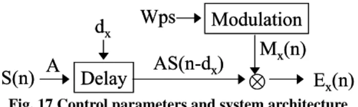
2.3.1 System Architecture
The system architecture and its relationship with the control parameters are shown in Fig. 17. While S(n) represents the original host signal, the delayed signals are defined in Eqs. (3) and (4), and the modulated echo signals are defined as Eqs. (8), (9) and (10).
Substituting Eqs. (3) and (4) into Eqs. (8) and (9) yields
)
(
*
)
(
)
(
0 0 0n
AS
n
d
M
n
E
=
−
(21) and)
(
*
)
(
)
(
1 1 1n
AS
n
d
M
n
E
=
−
. (22)Substitute Eqs. (10), (21) and (22) into Eq. (11) can obtain the combined embedding signal E(n) as
) ( * ) ( ) ( * ) ( ) ( * ) ( ) (n ASn d0 M0n ASn d1 M1n ASn M n E = − + − + N . (23)
Replacing the E(n) term in Eq. (13) with the above expression yields 2 1 1 0 0 1 ) ( * ) ( ) ( * ) ( ) ( * ) ( ) ( ) (' A n M n AS n M d n AS n M d n AS n S n S N + + − + − + = . (24)
In fact, only one of the embedding signals, E0(n),
E1(n) and EN(n), should have a non-zero value at any time
because only one of the modulators values can have a value of one in any block, when the block boundary condition is not considered. When the embedded bit is digit ‘0’, S’(n) would simplify to
2 0 1 ) ( ) ( ) ( ' A d n AS n S n S + − + = . (25)
Likewise, if the embedded watermark bit is digit ‘1’, S’(n) is 2 1
1
)
(
)
(
)
(
'
A
d
n
AS
n
S
n
S
+
−
+
=
. (26)Otherwise, when the block contains no watermark, S’(n) becomes 2
1
)
(
)
1
(
)
(
'
A
n
S
A
n
S
+
+
=
. (27)Based on the S’(n) functions, Eqs. (25), (26) and (27), and the autocorrelation definition functions, Eqs. (15) and (16), the discussion of the parameters influence can now proceed.
2.3.2 Echo Magnitude
The magnitude of echo is assigned for the decay percentage of delay signals. The magnitude value assignment needs to consider both the recovery accuracy rate and the audio quality. When the echo magnitude is too large, it can be directly seen that the audio quality of the watermarked signal would degrade. On the other side, when the echo magnitude is too small, the recovery accuracy rate would become too low for correctly identify the watermarked content. The relationship between the recovery accuracy rate and the echo magnitude is illustrated as follow.
The accuracy of watermark extraction is highly related to the difference between Cor(d0) and Cor(d1). In
other words, if the theoretical value of |Cor(d0) – Cor(d1)|
is large, then the actual value would be less influenced by the local characteristics of any single block signal. For example, the autocorrelation value of a small block in the original host audio may have a sudden peak at time d0,
while in reality a watermark digit ‘1’ is to be embedded. After the watermark digit ‘1’ embedded, it is hard to say whether Cor(d1) would be larger than Cor(d0) after the
echo is added, or if Cor(d0) would be larger because of
the local property of the host audio segment. Further examination of Cor(d0) and Cor(d1) is as follows:
Assuming the situation described in the previous paragraph occurs, than the appropriate expression for S’(n) comes from Eq. (26) where digit ‘1’ is embedded. Substituting S’(n) into the autocorrelation function, then the autocorrelation values of d0 and d1 are
∑ ∑ − + − − − + − − + − − + − = 2 1 0 1 1 2 0 1 0 1 0 0 (() ( )) )) ( ) ( ) ( ) ( ) ( ) ( ) ( ) ( ( ) ( d n AS n S d d n S d n S A d n S d n AS d d n S n AS d n S n S d Cor (28) and ∑ ∑ − + − − + − + − + − = 2 1 1 1 2 1 2 1 1 1 )) ( ) ( ( )) 2 ( ) ( ) ( ) 2 ( ) ( ) ( ) ( ( ) ( d n AS n S d n S d n S A d n AS d n S n AS d n S n S d Cor . (29)
In Eq. (28), the value of terms S(n)*S(n–d1–d0) and
S(n–d1)*S(n–d0) can be neglected based on the
autocorrelation characteristics, which assumed that the autocorrelation function has peaks only at time d0 (the
original host audio segment characteristic) and at time d1
(where the echo embedded). Thus, Eq. (28) is reduced to
S(n)
A
d
xAS(n-d
x)
Modulation
Wps
Delay
E
x(n)
M
x(n)
S(n)
A
d
xAS(n-d
x)
Modulation
Wps
Delay
E
x(n)
M
x(n)
∑ ∑ − + − − − + − = 2 1 0 1 1 2 0 0 )) ( ) ( ( )) ( ) ( ) ( ) ( ( ) ( d n AS n S d d n S d n S A d n S n S d Cor . (30)
In Eq. (29), under the same reasoning, the term
S(n)*S(n–2d1) can be ignored, and the equation is reduced
to ∑ ∑ − + − − + − + − = 2 1 1 1 2 1 2 1 1 )) ( ) ( ( )) 2 ( ) ( ) ( ) ( ) ( ( ) ( d n AS n S d n S d n S A d n AS d n S n S d Cor . (31)
It is still unclear whether the value of Cor(d0)
would be larger than Cor(d1) when A is small, because the
terms S(n)*S(n–d0) and S(n)*S(n–d1) are both large.
When A is large, the value of Cor(d1) would certainly
increase more quickly than the value of Cor(d0). By
inspection, the sub-terms of Cor(d1) are dominated by the
A*S2(n–d
1) term instead of the A2*S(n–d1)*S(n–d1–d0)
term, because A is always larger than A2, since 0<A<1 is
assumed.
An induction from the above condition is made.
Hyporeport 1: “When a larger echo magnitude is
assigned, a higher recovery accuracy rate can be attained, and vice versa.”
This hyporeport is verified with system simulation in Chapter 4, and the proper range for echo magnitude assignment would be given.
2.3.3 Watermark Embedding Rate
The watermark-embedding rate is defined as the number of blocks can be segmented within one single second audio. In other words, Wps is the number of watermarking information units can be embedded in per minute audio signal. The extractability of the hidden information and the information transmission rate need to be considered before assigning the watermark-embedding rate. The upper boundary of the watermark-embedding rate is constrained by the extractability, because the watermark could hardly be correctly extracted when the block size is too small. However, we need a larger watermark-embedding rate to get a higher information transmission rate. The value constrain of the watermark-embedding rate is discussed as follow.
Based on the same situation assumed in last section: There exists an autocorrelation peak at time d0 in the
block, and the embedded watermark digit is ‘1’. The corresponding expression for Cor(d0) and Cor(d1) are
defined in Eqs. (30) and (31), and A now has a fixed value. If the difference of Cor(d0) and Cor(d1) is
calculated term by term, |Cor(d0) – Cor(d1)| is
∑
∑
−
+
−
−
−
−
−
+
−
+
−
−
−
=
∆
2 1 0 1 1 1 2 1 2 0 1))
(
)
(
(
))
(
)
2
(
)(
(
)
(
)
(
)
(
)(
(
(
d
n
AS
n
S
d
d
n
S
d
n
S
d
n
S
A
d
n
AS
d
n
S
d
n
S
n
S
. (32)On average, as a small difference is gathered from one summation term, the large difference can be reached with many terms. In other words, with a larger block size, the difference between the autocorrelation values would be more obvious. The local autocorrelation characteristic of a small block signal may not be representative of the overall characteristic of the entire host signal. When the segment size is larger, there is a higher probability to reduce the random fluctuations in the summation terms that may induce extraction error.
We can make another induction based on the discussion above.
Hyporeport 2: “When a lower watermark-embedding
rate is given, and consequently, larger block size is assigned, a better recovery accuracy rate can be obtained, and vice versa.”
This hyporeport is also verified with system simulation in Chapter 4, and the proper range for watermark-embedding rate assignment would be given.
2.3.4 Delay Values and Delay Distance
When generating the echo signals for a watermark, a varied delay time is assigned for each echo. The influence on recovery error rate caused by delay times is a little different from the one caused by echo magnitude and watermark-embedding rate. This kind of error is much more related on the autocorrelation characteristic of both the local block and the overall watermarked audio signals. As shown in Fig. 16, the autocorrelation value is pretty high when the time distance from the origin is small. This property implies when the delay value is small, the autocorrelation calculation of the watermarked audio will be primarily influenced by the high autocorrelation of the host signal. In other words, there will be some instances when in fact the watermark digit ‘1’ is embedded, but the result Cor(d0) > Cor(d1) is obtained for
a large autocorrelation value that existed at time d0. When
d1>d0 is assumed, the extraction algorithm would not be
able to determine whether the watermark is digit ‘0’ or digit ‘1’, because the delay d0 lies within the section
where the large original autocorrelation value is initially large. In this situation, although Cor(d0) is larger than
Cor(d1), the influence by the existing high correlation at
time d0 may overwhelm the correlation that is produced
by the echo at time d1. Many errors may occur by
improperly extracting digit ‘1’s as digit ‘0’s. As the value of d0 decreases, the likelihood of extraction errors
increases. Thus, delay values should be constrained by the autocorrelation characteristic of the host audio, and must not be too small in order to avoid the errors caused by high correlation of the original audio. Based on the experimental results shown in Fig. 16, the average allowed value of the shorter delay should be larger than 0.6msec to avoid the influence from the high correlation of the original signal.
Similar problems may also occur when the delay distance, |d0 – d1|, is too small, for the relationship
between the two delay signals is much the same as the one between the delay and the original signals. Examine Eqs. (28) and (29). Assume that d0>d1 and the embedded
bit is ‘1’. When the distance between d0 and d1 is very
small, the S(n)*S(n–d1–d0) term in Cor(d0) becomes fairly
significant. Although S(n)*S(n–d1–d0) is theoretically
smaller than S(n)*S(n–d1), there is still a high
autocorrelation at time d1+d0 in the watermarked audio
due to the echo that exists at time d1. This correlation
makes S(n)*S(n–d1–d0) a large percentage of S(n)*S(n–d1),
which is much greater than zero, and cannot be ignored. Under this situation, if the other additional terms of
Cor(d0), such as S(n)*S(n–d0), are not small either, an
between Cor(d0) and Cor(d1) would not be distinct
enough due to the correlation between the two autocorrelation functions.
From this analysis, two assumptions are made based on the small delay distance problem described above.
Hyporeport 3: “An extraction error is more likely to
occur when the smaller delay lies too close to the original signal.”
Hyporeport 4: “Better recovery accuracy rate can be
reached when a longer delay distance is assigned, and vice versa.”
The two hypotheses about delay are verified with system simulation in Chapter 4, and the proper range for delay value assignment and the suitable distance between the delays would be given.
2.3.5 Analysis Based on Parameters
As mentioned before, the recovery accuracy rate and the quality of the watermarked audio are the most important properties of a watermarking technique design. While the accuracy rate of extraction is highly dependent on the assignment of the control parameters in the echo data hiding techniques, the combinations of various control parameters assignment would obtain quite different results. In order to achieve a desired recovery accuracy rate, some proper combinations of the control parameters must be selected. In practical application, the highest recovery accuracy rate is not always required, and we may only wish for an acceptable accuracy with a better audio quality or a higher watermark-embedding rate. Thus, when a parameter is assigned for high accuracy rate, the others can be selected from a much larger range and still obtain the acceptable recovery accuracy rate.
From Hyporeport 1 and Hyporeport 2, we can make another assumption:
Hyporeport 5: “When a larger magnitude is assigned, a
higher watermark embedding rate (smaller block size) is allowed for an acceptable recovery accuracy rate.” In other words, “Lower watermark embedding rate (larger block size) is needed to achieve an acceptable recovery accuracy rate when smaller magnitude is given.”
This assumption is useful for us to adjust the control parameters when only a certain level of accuracy rate is required. For example, if we increase A, the recovery accuracy rate will consequently increase. But if this increased recovery accuracy rate is not needed, we can then instead increase the Wps for higher watermark-embedding rate, which is another important property of the watermarking techniques. Or on the opposite side, when a low Wps is given as the high recovery accuracy is reached, a smaller A can be assigned to make the audio quality of watermarked audio better.
Based on Hyporeport 1, Hyporeport 2 and
Hyporeport 4, the additional correlations between the
parameters can be deduced.
Hyporeport 6: “When a longer delay distance is chosen,
a smaller magnitude is allowed for an acceptable recovery accuracy rate.”
Hyporeport 7: “When a larger delay distance is given, a
suitable recovery accuracy rate is achieved with a
higher watermark embedding rate.”
The hypotheses above give more flexibility to the assignment ranges of the parameters in echo data hiding techniques, and they serve as the foundation for some of the modification techniques we would like to propose in the next chapter.
Chapter 3 System Modification
Several problems exist in the echo data hiding techniques. One disadvantage of this watermarking method is the echo signal cannot exist in the segments of silence. Any decay of magnitude zero is still zero, there is no use trying to add an echo in the silent parts. Thus, the echo watermark embedded in the silent regions cannot be correctly extracted and would increase the recovery error rate. Another weakness of the echo data hiding techniques is its low information transmission rate comparing with some other approaches. In the previous system design, only one bit of watermark information (‘0’ or ‘1’) can be added in a single block of the host audio. Generally speaking, in echo data hiding, only about two to 64 blocks can be segmented for echo embedding in each second of the audio signal, while 44.1k bits of data per second is allowed in low-bit coding approaches [14]. In a word, the watermark-embedding rate of the echo data hiding system is too low for information transmission, and we wish to increase the information transmission rate.
In this chapter, we will focus on these two problems of the echo data hiding techniques mentioned above in hopes of improving the echo data hiding techniques as a better watermarking system.
3.1 Bypassing Silence
Since embedding echoes in the silent or small energy blocks is useless for extraction of the hidden echo data, skipping these blocks may be the only choice. To skip the silent or small energy blocks, the system of echo data hiding is modified. The system modification is adding a procedure of energy check, in which a threshold is assigned for bypassing the silent blocks and the small energy blocks.
3.1.1 Causes of Extraction Errors
It can be directly observed that the added echo makes no difference on the signal magnitude in silent
segments, as Fig. 18 shows. The extraction error occurs when a digit misread is made in watermark extraction procedure or when the embedded digit could not be decided by autocorrelation check; that is, the added echo makes no difference.
Proof that an echo could not exist in the silent segments can be easily demonstrated. A signal with an echo can be represented as
)
(
)
(
)
(
'
n
S
n
AS
n
d
S
=
+
−
. (33)When S(n) in the segment is zero, S(n–d) is also zero in the same segment. The extraction of watermark data depends on the difference between the autocorrelation values of the watermarked signal at the two assigned delay positions. As long as there is no difference between
Cor(d0) and Cor(d1) in the silent segments, for the signals
are both zero, it is useless to embed data into these silent segments.
Now let us consider the segments with small energy. If the magnitude of the sample is only about one-quantization-step large, which is represented as ‘one’ after quantization, adding a small echo on the sample would not make any difference in the resultant sample magnitude, which is still ‘one’. The digital audio signals are usually quantized before storage. Performing quantization means replacing the signal magnitude with its nearest integer. When embedding an echo, for any integer K, K A K AK K 2 1 0 when ) t( nearest_in + = < < (34) and 1 2 1 when 1 ) t( nearest_in + ≥ + ≤A< K K AK K . (35)
From Eqs. (34) and (35), in order to make a difference in magnitude after data embedding, A must be larger than 1/2 when K=1, and be bigger than 1/4 when
K=2, etc. That is to say, when the amplitude of a sample
is K and an echo with scaling factor A is added, the value of A*K must be larger than 0.5 to make a difference in the
![Table 2 Characteristics of watermarking techniques Reference: [14] [18]](https://thumb-ap.123doks.com/thumbv2/9libinfo/8112376.165585/7.892.181.693.93.262/table-characteristics-watermarking-techniques-reference.webp)