國
立
交
通
大
學
資訊科學與工程研究所
碩
士
論
文
一種轉換二點五維圖形物體成三維圖形物體的
方法
An Approach for Transferring 2.5D Graph Entities into 3D Ones
研 究 生:梁赫廷
指導教授:王豐堅 教授
一種轉換二點五維圖形物體成三維圖形物體的方法
An Approach for Transferring 2.5D Graph Entities into 3D Ones
研 究 生:梁赫廷 Student:Hoting Liang
指導教授:王豐堅 Advisor:Feng-Jian Wang
國 立 交 通 大 學
資訊工程與科學研究所
碩 士 論 文
A ThesisSubmitted to Institute of Computer Science and Engineering College of Computer Science
National Chiao Tung University in partial Fulfillment of the Requirements
for the Degree of Master
In
Computer Science
March 2011
Hsinchu, Taiwan, Republic of China
I
一種轉換二點五維圖形物體成三維
圖形物體的方法
研究生: 梁赫廷 指導教授: 王豐堅 博士 國立交通大學 資訊工程與科學研究所 新竹市大學路 1001 號 碩士論文摘要
很多 Flash 遊戲由二點五維的技術所開發。基於一個二點五維的遊戲,直接 發展一個三維的版本是需要重新架構遊戲的規則、物體和世界等等,且可能特別 會引起使用者對這個遊戲的混亂。因此,藉由並行且逐漸地(1)轉換現存的二點 五維物體成為三維物體(2)加入額外的三維物體將一個二點五維的遊戲升級成三 維的遊戲。在每一次的更新中,每個版本都保有原本二點五維遊戲的交互作用的 能力。 本文中,為了上述的工作,我們提出一種改變程序。這個改變程序能分為三 個子程序:(1)在一個二點五維的遊戲中替每個二點五維的物體準備三維的皮膚 層。(2)藉由逐漸加入三維物體在這個遊戲裡以提供一些三維的特色。(3)如果物 體的定義都跟三維特色有關,則藉由將一個三維的舞台置換掉一個二點五維的背 景使得此遊戲轉換成一個三維的遊戲。因此,這個改變程序能將一個現存的二點 五維遊戲升級成一個二點五維-三維混用的遊戲、或是一個全三維的遊戲且沒有 引入非必要的混亂。 關鍵字: Flash actionscript、二點五維-三維混用遊戲、二點五維和三維顯示、二點五維和三維交互作用II
An Approach for Transferring 2.5D Graph
Entities into 3D Ones
Student: Hoting Liang Advisor: Feng-Jian Wang Institute of Computer Science and Engineering
National Chiao Tung University
1001 University Road, Hsinchu, Taiwan 300, ROC
Abstract
Many Flash games were developed with 2.5D technique. These games are restricted with single plain and limited views. Building a 3D version based on a 2.5D game directly is needed to reconstruct the game rules, entities and world, etc., and especially might cause users’ chaos for the game. Therefore, to upgrading a 2.5D game as a 3D one might be valuable by concurrently and gradually (1) transferring existing 2.5D entities into 3D one and (2) adding extra new 3D entities. Each new version owns the interactive activities of original 2.5D game in each upgrade.
In this thesis, we propose a modification process for above work. The modification process can be divided into three sub-processes: (1) Prepare a 3D skin for each 2.5D entity in a 2.5D game. (2) Provide some 3D features by adding 3D entities into the game. (3) If the entity definitions are associated with 3D features, the game is transferred into a 3D game by replacing the 2.5D scene with a 3D stage.
III
Therefore, the modification process may upgrade an existing 2.5D game to a 2.5D-3D hybrid game or fully 3D game without introducing non-necessary chaos.
Keywords: Flash actionscript, 2.5D-3D hybrid game, 2.5D and 3D rendition, 2.5D
IV
本論文 承蒙
財團法人中華扶輪教育基金會
台中中央社
於 2010-2011 年度提供『中華扶輪獎學金』
謹致謝忱
V
致謝
本篇論文得以完成,最主要感謝我的指導教授王豐堅教授。在交通大學就學 期間讓我在軟體工程、工作流程領域中能夠深入了解,並且獲得許多寶貴的知識 及經驗。另外,也十分感謝我的口試委員吳毅成博士、林志敏博士以及留忠賢博 士的寶貴意見,得以補足論文中的不足之處。 其次要感謝實驗室的學長姐、同學及學弟妹兩年間的指導、照顧與砥礪。在 進入交大這個新環境的時候,得到實驗室王靜慧學姊、許懷中學長以及黃培書學 長許多課業及研究方面的指導。在研究過程中,許懷中學長對我論文架構、寫作 的指導,並在我氣餒的時候不斷地鼓勵我,讓我在研究生活中遇到瓶頸的時候能 順利克服,不管是專業的知識、研究技巧以及文章寫作都讓我受益良多,因為有 學長不厭其煩的指導,本篇論文才得以順利完成。 最後要感謝我的父母、親朋好友,能讓我在無後顧之憂的狀況下全力完成學 業,並適時的激勵與關心,更是我努力不懈的動力來源,謝謝你們。VI Table of Contents 一種轉換二點五維圖形物體成三維圖形物體的方法... I 一種轉換二點五維圖形物體成三維圖形物體的方法... I 一種轉換二點五維圖形物體成三維圖形物體的方法... I 摘要... I An Approach for Transferring 2.5D Graph Entities into 3D Ones ... II Abstract ... II 本論文 承蒙...IV 致謝...V Table of Contents ...VI Table of Figures ...VII
Chapter 1 Introduction ... 1
Chapter 2 Background ... 4
AgentCubes: Incremental 3D end-user development ... 4
AdvancED ActionScript 3.0 Animation ... 5
3D in Flash ... 6
Chapter 3 Consistency between 3D Entity and 2.5D Coordinates ... 7
Section 3-1 Transforming a 2.5D game into a 3D version ... 7
Section 3-2 Coordinate transformation – a fundamental Issue ... 9
Section 3-3 A unification Technique for transformation ... 13
Chapter 4 Interaction and Rendition between 2.5D and 3D Entities ... 16
Section 4-1 Interaction Problem in different dime dimensions ... 16
Section 4-2 A pattern for graph entities in different dimensions ... 19
Section 4-3 The virtual class inherits from an appropriate 2.5D class ... 24
Section 4-4 Rendering problem containing 2.5D and 3D graph entities ... 27
Section 4-5 A class structure for Rendition Integration ... 30
Chapter 5 Modification Process from a Pure 2.5D Game to a Hybrid or 3D Game 33 Section 5-1 Developing process from a 2.5D(2.5D) game to a hybrid game . 33 Section 5-2 Developing process from a hybrid game to a fully 3D game ... 36
Section 5-3 Modification Process constructed by three processes ... 43
Chapter 6 Conclusion and Future Work ... 45
VII
Table of Figures
FIGURE 2-1THE FUNCTIONS OF TRANSFORMATION FOR 2D AND 2.5D COORDINATE SYSTEM IN
“COLLISIONTEST” ... 6
FIGURE 3-1(1) ANTICIPANT POSITION OF THE 3D BALL (2) ACTUAL POSITION OF THE 3D BALL ... 10
FIGURE 3-2 PROJECTED PERSPECTIVE FROM VANISHING POINT [9] ... 11
FIGURE 3-3 (1)AWAY3D COORDINATE SYSTEM (2)FLASH COORDINATE SYSTEM ... 12
FIGURE 3-4EXPLANATION FOR POSITION OF THE RED BALL ... 12
FIGURE 3-5TRANSFORM 2.5D COORDINATE SYSTEM TO 3D COORDINATE SYSTEM. ... 14
FIGURE 3-6THE FUNCTIONS FOR TRANSFORMING 2D COORDINATE SYSTEM TO 3D COORDINATE SYSTEM ... 15
FIGURE 4-1(1)BEFORE THE COLLISION IN ORIGINAL 2.5D GAME (2)COLLISION (SUCCESS) ... 17
FIGURE 4-2(1)BEFORE THE COLLISION IN THE HYBRID VERSION (2)COLLISION (FAILURE DETECTION) 17 FIGURE 4-3THE CLASS PATTERN FOR INTERACTION ... 19
FIGURE 4-4THE MODEL OF INTERACTION FOR 2.5D ENTITIES ... 20
FIGURE 4-5THE MODEL OF INTERACTION FOR 2.5D ENTITY AND 3D ENTITY ... 21
FIGURE 4-6THE MODEL OF INTERACTION FOR 3D ENTITIES ... 22
FIGURE 4-7COLLISION FOR THE 3D ENTITY AND 2.5D ENTITY ... 23
FIGURE 4-8INTERACTION EXCEPTION OF A ENTITY3D ... 23
FIGURE 4-9(1)LAYER OF FRONT CUBE IS FRONT. (2)LAYER OF BEHIND CUBE IS FRONT. ... 27
FIGURE 4-10(1)THE GREY CUBE IN TOP-RIGHT CORNER OF THE BLUE CUBE (2)THE GREY CUBE IN BACK OF THE BLUE CUBE (3) THE GREY CUBE IN TOP-LEFT CORNER OF THE BLUE CUBE ... 29
FIGURE 4-11THE CLASS STRUCTURE FOR RENDITION OF DEPTH ... 30
FIGURE 4-12(1) THE GREY CUBE IN TOP-RIGHT CORNER OF THE BLUE CUBE (2) THE GREY CUBE IN BACK OF THE BLUE CUBE (3) THE GREY CUBE IN TOP-LEFT CORNER OF THE BLUE CUBE ... 32
FIGURE 5-1(1)THE HYBRID GAM (2)THE 3D PLANE REPLACES THE 2.5D SCENE ... 37
FIGURE 5-2(1)ADJUST THE PROPERTIES OF (2)CHANGE THE ANGLE AND COOR- THE 3D ENTITIES DINATE OF THE CAMERA 39 FIGURE 5-3(1)2.5D MOTION OF THE 3D ENTITIES (2)3D MOTION OF THE 3D ENTITIES ... 39
FIGURE 5-4 THE FUNCTION OF COLLISION DETECTION IN FULLY 3D GAME ... 40
FIGURE 5-5THE GAME WORLD FROM DIFFERENT VIEWPOINTS ... 41
1
Chapter 1 Introduction
Today, Flash is more than half of use as the standard plug-in for displaying interactive multimedia and graphic content over World-Wide Web. Many browser games [1] and casual games [2] are developed through Flash Actionscript. These games are light-weighted because they need only browsers and the plug-ins like Flash Player for operation without installation of specific software. With Flash, the games also have problems of using hardware resources of personal computers like hardware-accelerated graphics, which are necessary for more computing power. Because of few limits, they can be played when user has a device and Internet.
These games are traditionally developed as 2D games or its isometric variants, 2.5D game [3], and are more or less restricted with a single plain and limited views. Animation, motion and rotation of 2.5D entities in these games are presented through changing of pictures. For example, the aspects of a 2.5D entity are usually presented by various hand-drawing pictures. When user turns the entity from one aspect to another, the representation of the entity is changed from one picture to the corresponding one. However, 2.5D representation is limited in expressing depth of a scene, such as the information hidden for overlapping entity. Besides, Flash may not provide the rich 3D applications in its own library. Thus, the programmer focuses on developing the 2.5D game.
2.5D (2D)-3D hybrid applications are widely adopted in various domains. 3D Geographic Information System [4] , eyegaze analysis [5], etc. are the representative 2.5D (2D)-3D hybrid applications which mix 2.5D (2D) views/ entities with 3D ones
2
for displaying more plentiful visual information to the users. Nowadays, Flash is associated with many 3D libraries, e.g. Papervision3D, Sandy 3D, Away3D [8], etc. However, 2.5D (2D)-3D hybrid applications are rarely discussed in development of Flash games. On the other hand, to upgrade a 2.5D game as a 3D game is by building another 3D version directly. When users play the 3D version, they will feel the chaos between 2.5D and 3D versions. It might be valuable by applying one way adopting the 2.5D-3D hybrid applications to avoid the chaos. Therefore, we may present the modification process generates 2.5D-3D hybrid versions which are added 3D entities gradually without rewriting the logic related to game rules and strategies, and provide some 3D features for better “look & feel” with animation, motion and rotation of 3D entities. Besides, users which play the 2.5D-3D hybrid versions are easy to feel these 3D features in the 2.5D-3D hybrid versions.
In this thesis, we develop a modification process expected to be applied on the development of 2.5D-3D hybrid Flash games from its initial 2.5D versions. It describes the details for upgrading a 2.5D Flash game by gradually replacing 2.5D entities with 3D ones and adding extra 3D entities. The modification process is a gradual procedure. Therefore, the upgraded version reserves the interactivities of original 2.5D version and gives players additional entertainment with 3D features. The rest of this paper is organized as following: In chapter 3, we illustrate our motivation and a fundamental issue: Coordinate transformation. In chapter 4, we discover two main problems for developing 2.5D-3D hybrid versions: 1. Interaction between 2.5D and 3D entities, 2. Rendition for depth of 2.5D scene. We explain the problems and solutions in this chapter. In chapter 5, the modification process is presented in our thesis. With the development process, 2.5D game can be upgraded to 2.5D-3D hybrid game or fully 3D one. Finally chapter 6 concludes this thesis and
3 presents our future work.
To simplify the discussion, hybrid game is used to represent 2.5D-3D hybrid game.
4
Chapter 2 Background
In this chapter, we survey related works which upgrade 2.5D games to 3D games, and introduce the 2.5D game model and 3D library. AgentCubes: Incremental 3D
end-user development surveys related process which is used to upgrade 2D games to
3D games. 3D in Flash and AdvancED ActionScript 3.0 Animation introduce the 2.5D game model and 3D library.
AgentCubes: Incremental 3D end-user development
AgentCubes [6] is an Incremental 3D end-user development tool for creating 2.5D and 3D games. In AgentCubes, the programmer is asked to develop a 2.5D game, and design rules and strategies of games first, according to the tools/libraries provided. In this step, he/she does not worry about 3D model, orientation and location of entities for the 3D version. Second, when he/she wants to construct a corresponding 3D game, he/she is asked to construct the corresponding code and data for all the classes and entities at a time.
Obviously, upgrading a 2.5D game to a 3D game at a time might introduce a lot chaos. For example, because lots of 3D classes and entities of classes are introduced, programmers can not build the 3D game easily according to their experience. [6] leaks of additional tools or methodology to help programmers to upgrade the existing 2.5D games to 3D games for coding.
5
AdvancED ActionScript 3.0 Animation
When a programmer develops a game by using Flash Actionscript, he/she has many problems in all respects of the game, such as animations and interactions of entities. In [7], Keith provides advanced algorithms and libraries for Flash game, such as collision detection, steering behaviors and Isometric Projection, etc. The programmer may quickly develop a Flash 2D and 2.5D game, and solve these problems with the goal of efficiency and precision.
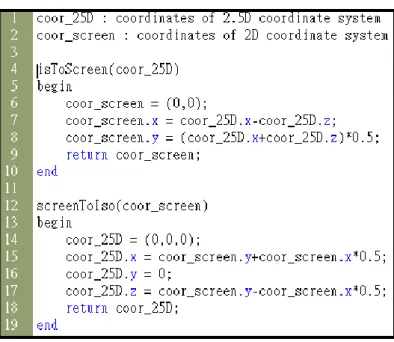
The program of “GridCollision” is a 2D game, and the ones of “MapTest” and “CollisionTest” are a 2.5D game in this book. These programs display the basic properties like size and angle of the game world, motion and interaction of entities, etc. For example, Figure 2-1 illustrates how to transform a coordinate between the 2D and 2.5 coordinate systems, where “isoToScreen” works for 2D to 2.5D coordinate systems and “screenToIso” works for reverse direction. In this thesis, our methodology is based on the examples in these games.
6
Figure 2-1 The functions of transformation for 2D and 2.5D coordinate system in “CollisionTest”
3D in Flash
Away3D [8] is a real-time 3D engine for Actionscript 3.0 in Flash. The engine is an Open Source that is continuously maintained and added support by new features for new Flash Players. On the other hand, it is free to use for any purpose such as commercial applications. Away3D is easy to learn and show 3D features for beginners.
The book, “3D in Flash”, is a reference book for Away3D, and illustrates how to write a 3D application in detail. It explains the capability of each class of Away3D library based on examples of programs, such as applications of the Camera class. In this thesis, we use Away3D as example of 3D library to upgrade 2.5D games to 3D games.
7
Chapter 3 Consistency between 3D Entity
and 2.5D Coordinates
Section 3-1 Transforming a 2.5D game into a 3D version
2.5D game provides lots of fun through rich playing ways like “side-scrolling games” and displays of sophisticated graphs. However, the 2.5D games are restricted to a single plane and limited views. For example, the rotation of the 2.5D entity is difficultly displayed in the 2.5D scene based on changing of pictures. The limited views are hard to clearly represent the whole game world like the back of a barrier.
To overcome the limitation of the single plane, it might allow to let the programmer add 3D entities into the 2.5D game, because the 3D entity is a complete individual rather than a set of pictures and can provide better visual effects, such as motion, rotation and animation. Correspondingly, it is interesting to transfer a 2.5D game to a 3D version with this technology. Thus, we construct such a 3D game with two steps: (1) Let the programmer develops a hybrid game from a 2.5D game through gradually adding or replacing 2.5D entities with 3D ones, where the logic related to game rules and strategies is maintained for reducing the upgrading cost. (2) Once each entity is the 3D entity in the 2.5D scene, the programmer can transform such a hybrid game into a 3D game with a given facility.
8
replacement, there are at least three factors to be solved, including:
(1) Some properties of the 3D entity need be modified for compatibility in the 2.5D game. For example, a 3D entity has to be taken off its third dimension of location when put in a 2.5D scene.
(2) The interaction behavior between existing entities and 3D entities need be built based on the current behavior in the game.
(3) The relative depth between 2.5D and 3D entities need be shown in the hybrid game.
When programmers replace the 2.5D scene with a 3D one, there are at least two factors to be solved, including:
(1) The properties of the 3D scene are set up based on those of the 2.5D scene.
9
Section 3-2 Coordinate transformation – a fundamental Issue
We present a technique between 2.5D and 3D entities for interaction and rendition of depth in the following chapters. The technique makes each 3D entity which is put into the 2.5D scene to have a corresponding 2.5D entity for helping interaction and rendition of depth. To finish this technique, we should overcome the problem of coordinate transformation.
Before entering the study, a fundamental issue occurs: to present an entity of 3D coordinate in a 2.5D(2D) system.
When a 3D entity, supported by 3D library such as Away3D [8], is put into a 2D scene, the coordination system corresponding to the entity might cause it to be shown at an unexpected place in the scene. For example, in Figure 3-1, the red ball is a 3D entity and the yellow ball is a 2D one. When the red ball is put at the left column of the yellow ball, the expected scene is shown as in Figure 3-1 (1). However, the real scene might show that the red ball is at one column right and 3/2 row up of the yellow ball as in Figure 3-1 (2). Therefore, the coordinates of a 3D entity have to be reorganized for display consistency in a scene. Similarly, the coordinates of a 2D entity have to be re-organized when it is put into a 3D scene.
10
Figure 3-1 (1) anticipant position of the 3D ball (2) actual position of the 3D ball
Intuitively, there are two reasons causing above defects. First, the origin of the coordinate system in Away3D is different from that in Flash (for 2D display), the top-left corner of a scene. In Away3D, the origin is at the vanishing point representing the position where entities converge the further away they are. The vanishing point is usually at the center of a scene, and is the foundation for building a 3D scene. Figure 3-2 explains how a 3D world is established through a 3D library. A 3D entity can be displayed in a 2D scene with projection from the vanishing point. The projection indicates illusion of depth and distance among 3D entities when displaying 3D entities closer to the screen with larger size, and vice versa.
11
Figure 3-2 projected perspective from vanishing point [9]
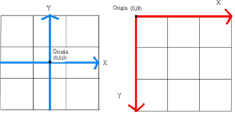
Secondly, Away3D [8] uses the “Cartesian” coordinate system adopted in mathematics and geometry. Let x-axis be the abscissa, and y-axis be the ordinate, and z-axis be the applicate. The x-axis value of a point is positive if it is at the right of origin, and negative if left. The y-axis value of a point is positive if it is higher than the origin, and negative if lower. However, the value of y-axis is reverse in Flash; i.e. the y-axis value of a point in Flash is negative if it is higher than the origin, and positive if lower.
Figure 3-3 illustrates the differences between the coordinate systems adopted in the 2D and 3D libraries. Figure 3-4 helps to explain the problem of position for the red ball. We draw the 2D and 3D coordinate systems in this figure. Therefore, the position of the red ball is calculated form origin in 3D. The x value of the red ball is smaller than the x value of the yellow ball but the red ball is at the right side of the yellow one. The y-axis in the 2D library is inverted for 3D, so the red ball is at top of the yellow one.
12
Figure 3-3 (1)Away3D coordinate system (2)Flash coordinate system
13
Section 3-3 A unification Technique for transformation
In this section, to unify the 2.5D and 3D coordinate systems, we construct the formula to transform coordinate values from 2D to 3D as followings.
position.3Dx = position.2Dx-vpoint.x +c_of.x;…………..(1) position.3Dy = - (position.2Dy-vpoint.y) +c_of.y;……….(2)
The parameters used in the formula are listed and defined below:
position.2Dx: the x-axis value of a point in 2D coordinate system. position.2Dy: the y-axis value of a point in 2D coordinate system. position.3Dx: the x-axis value of a point in 3D coordinate system. position.3Dy: the y-axis value of a point in 3D coordinate system. vpoint: the point used in 2D coordinate system represents the vanishing
point in 3D coordinate system.
c_of : the visual difference has two attributes, c_of.x and c_of.y, used
for unifying 2D and 3D coordinates.
When a 3D entity is put into 2D coordinate system, the management of corresponding 2D and 3D coordinates of the entity can be handled with c_of and vpoint as in formula (1) and (2). The vpoint is at the center of the scene of 2D system. The values of vpoint can thus be defined as the difference of first two coordinates between 2D origin and 3D origin in 2D coordinate system. Therefore, to get position.3Dx and position.3Dy, the position.2Dx and position.2Dy are subtracted with the first two coordinates of vpoint individually. Since, the 2D entity exists in a plain surface only, and the 3D entity in a 3D scene is displayed with convex camera lens, corresponding to
14
a curved surface, a pair “c_of” is adopted to reduce a visual difference when putting a 3D entity at a position in a 2D scene. The value of c_of is defined based on the curve ratio of the 3D system and distance between the entity and 3D origin, i.e, c_of.x = dx * curve_ratio.x and c_of.y = dy *
curve_ratio.y.
Each 2.5D game has its own coordinate system for diagonal 2.5D scene also. Because 2.5D game simulates depth in 2D coordinate system with diagonally displayed scenes, it needs extra transformation when displaying a 2.5D entity on a 2D system. Usually, game systems transform 2.5D coordinate system into 2D one based on the documents of original game. Then, our formula can be worked for 2D coordinate to 3D one for coordinate consistency.
Let us use an example based on the codes of 2.5D game in [7] to show add an 3D entity in a 2.5 game. According to “isoToScreen” in Figure 2-1, we transform a 2.5D coordinate to a 2D coordinate, and use the 2D one adopting the functions, “screento3Dx” and “screento3Dy”, as Figure 3-5 illustrates. The functions are our formulas for transforming 2D coordinates into 3D coordinates as Figure 3-6 illustrates. With the functions for putting the values which are transformed from 2.5D to 2D coordinates, the 2.5D and 3D coordinate systems are unified.
15
Figure 3-6 The functions for transforming 2D coordinate system to 3D coordinate system
16
Chapter 4 Interaction and Rendition
between 2.5D and 3D Entities
Section 4-1 Interaction Problem in different dime dimensions
In a 2.5D game, a movable entity may interact with another entity when its boundary like the fringes of its image reaches that of the latter, if both are in the same layer of depth. For example, a collision occurs once the images of above two entities are overlapped their fringes in the same layer of depth. In Flash library [9], the method, “hitTest”, used for collision detection between two of “BitmapData”, “MovieClip” or “Sprite” entities in Flash does not support Away3D [8] entities. Similarly, the method supporting collision detection in Away3D cannot be adopted for general Flash entities either.
In a 2.5D coordinate system, the 2.5D game simulates depth with a diagonally displayed scene which is composed of finite grids. Each entity is put into 2.5D scene based on a set of specific grids namely v-grids, and its boundary is defined as the boundary of its v-grids in the 2.5D scene. When an entity is moved up, down, left or right, its v-grids is moved correspondingly, but its size and shape do not change. Figure 4-1 shows how 2.5D entities collide with each other through invocation of the function, “canMove”. When the grey cube moves to the blue cube as Figure 4-1 (1) shows, “canMove” detects the collision and feeds back to entities if there is an overlap between the boundaries of their v-grids. Then, the movement is
17
stopped by the application as Figure 4-1 (1) shows. As Figure 4-2 (1) shows, the grey cube as a 3D entity reaches to the blue one similarly. However, as the Figure 4-2 (2) and (3) shows, when the grey cube moves to the other, the grey cube passes through the blue one. Such a case indicates there is no collision detection because the function “canMove” does not support collision detection between 2.5D and 3D entities. Furthermore, currently there is even no method handling interactions between 2.5D and 3D entities in either Flash or 3D libraries. In next subsection, we will present a detection technique between 2.5D and 3D entities through the example of collision detection.
Figure 4-1 (1) Before the collision in original 2.5D game (2) Collision (success)
Figure 4-2 (1)Before the collision in the hybrid version (2) Collision (failure detection)
18
(3) After the collision
In this subsection, a technique enacting interactions between 2.5D and 3D entities is presented based on a way how the 3D entity is put into the 2.5D scene. For replacing a 2.5D entity with a 3D one, this way does not delete the replaced 2.5D entity. It uses the functions of Section 3-2 for covering the 2.5D entity with the 3D one. Under the premise of the way, we present the interaction between 2.5D and 3D entities. Therefore, the solution of this subsection is presented in next section.
19
Section 4-2 A pattern for graph entities in different dimensions
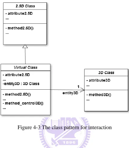
Figure 4-3 The class pattern for interaction
In this subsection, a class pattern enacting interactions between 2.5D entities and 3D entities is presented as in Figure 4-3. Each 3D class is associated with a virtual class which contains an entity3D, an instance of the 3D class. Besides, the virtual class is defined to inherit from the 2.5D class which is selected as in Section 4-3 . The virtual class instance, namely v-entity, may invoke the methods to pass the control message of exception handling to its entity3D.
On the other hand, the v-entity’s methods for 2.5D operations such as “method2.5D” can be classified into three categories. The first category contains the methods inherited from the 2.5D class, and they works among its inherited attributes and other 2.5D entities/v-entities. The methods of the
20
second category are derived by overriding those in the 2.5D class. The control of the entity3D is put into those methods. The third category contains the methods added for handling the interaction or synchronization of the entity3D and v-entity’s other attributes. For example, the v-entity needs to synchronize coordinates of itself and its entity3D due to the difference of 2.5D and 3D coordinate systems described in Chapter 3 . Besides 2.5D operations, the activity for the v-entity to control the entity3D appears repeatedly in different exception handlings. The “method_control3D()” is added to describe this activity and may be reused in the fully 3D version. Therefore, the 2.5D classed need not be modified, neither the 3D classes.
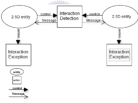
Figure 4-4 The model of interaction for 2.5D entities
Figure 4-4 illustrates how a 2.5D entity interacts with another in Flash. The entity checks the interaction(s) between them by using the function of interaction detection such as the function, “hitTestObject”, which is a
21
function of collision detection. When an interaction is detected, the function returns a message to both 2.5D entities to handle corresponding interaction exceptions individually.
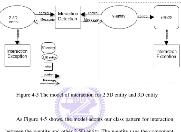
Figure 4-5 The model of interaction for 2.5D entity and 3D entity
As Figure 4-5 shows, the model adopts our class pattern for interaction between the v-entity and other 2.5D entity. The v-entity uses the component entity3D for rendition of the 3D entity. Therefore, the v-entity may use its 2.5D properties to interact with other 2.5D entities by the original methods which are inherited from the corresponding 2.5D class, and control the entity3D to do the exception handling of the interaction. For example, when an entity3D collides with a 2.5D entity, its v-entity uses the function of collision detection to work with other 2.5D entities. Once the function feeds back to the v-entity, the v-entity controls its entity3D for necessary 3D manipulation.
22
Figure 4-6 The model of interaction for 3D entities
Figure 4-6 shows the model adopted in our class pattern for the interaction between two 3D entities, and it is similar to Figure 4-5. Each v-entity interacts with the other for their entity3D. Once an interaction occurs, both v-entities control their entity3D for corresponding exception handling of interaction.
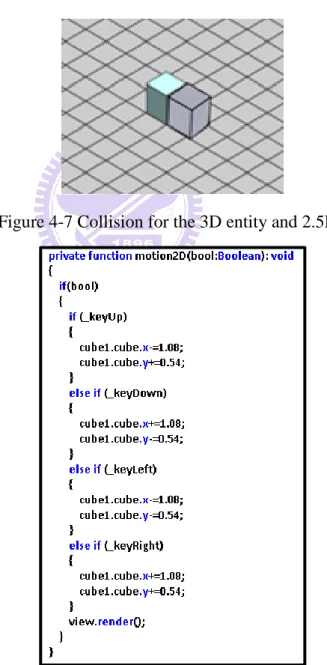
We adopt our class pattern into the example as Figure 4-2 shows in Figure 4-7. Blue cube is a 2.5D entity, and grey cube is an entity3D of corresponding v-entity which inherits from the 2.5D class of the blue cube. When the grey cube is moved to collide with the blue cube, the v-entity of the grey cube uses the function, “canMove”, to detect whether there is a collision between them. Once the function detects a collision between the v-entity and blue cube, it returns a “Boolean” value to the v-entity and blue cube. According to this value, the v-entity controls the motion of the grey cube in the 2.5D scene by using the method2.5D, “motion2.5D”, as Figure 4-8 shows. Therefore, the grey cube makes a stop rather than passes through the other. The 3D entity successfully interacts with a 2.5D entity for collision through our structure.
23
However, we do not solve the limit of interaction detections in this section. For example, “canMove” has a limit of detection, because it only checks the overlap of the grids between entities for collision detection. It does not provide the collision detection for high or low entities. In Chapter 5 , we shall upgrade the fully 3D game from a 2.5Dgame, and use the methods in 3D libraries for solving limits of interaction detection in 2.5D.
Figure 4-7 Collision for the 3D entity and 2.5D entity
24
Section 4-3 The virtual class inherits from an appropriate 2.5D class
According to the pattern in above section, the programmer should create a virtual class which contains an entity3D, an instance of its corresponding 3D class, and inherits an appropriate 2.5D class. An entity3D interacts with other 2.5D entities and entity3Ds based on its v-entity’s attributes inherited from the selected 2.5D class. During an interaction, if the v-entity cannot provide enough supporting attributes, the interaction fails. Thus, it is important to select an appropriate 2.5D class to be inherited by the virtual class. We present an algorithm of eleven steps for programmers to do the selection shown below, and construct the corresponding virtual class described in above.
Algorithm Class_Selection
Input: a 3D class Output: a 2.5D class begin
1: Get the number k, k is the number of capabilities of which each is corresponding to a distinct property of the input 3D class.
2: Search a class which contains these k capabilities from the 2.5D classes. If one is found, it is returned and the algorithm stops. 3: Set each of these capabilities with a distinct id, pi, 1≤i≤k, where pi
has higher priority than pj if i>j , and x=k-1.
4: Search a set of the class(es) which contain x of above k capabilities.
5: If there is no one which contains x capabilities, then x=x-1 and go to Step 4.
25
6. If there is only one class, then return the class and stop. 7: Get the id of highest-order capability among these classes.
8: If there is only one class containing id, then return this class and stop.
9: If id is the lowest-order capability of these classes, return one of the classes and stop.
10: Delete the class(es) not containing id.
11: Get the id of next-order capability among these classes; go to 8. end
Algorithm Class_Selection is applied to find the 2.5D class used as the parent class of the virtual class. Step 1 derives the capabilities of which each is corresponding to a distinct property extracted from the input 3D class. In the hybrid games discussed in the thesis, the properties of input 3D class are defined based on its operations. For example, if the entity3D is movable and collided, the motion and collision are selected as its capabilities. Similarly, each 2.5D class has its own capabilities derived from its own operations. For example, a 2.5D entity such as a barrier has no capability of motion. By comparing the capabilities of the entity3D with that of 2.5D classes, a 2.5D class containing all above k capabilities can be selected to be the parent class of the virtual class in Step 2. In other words, when this step finds such a 2.5D class, and the algorithm returns the class directly.
In case no one is selected in Step 2, a 2.5D class containing some of these k capabilities is selected to play the role. In our algorithm, Step 3 sets the priorities of these capabilities for the search in the following steps. Because the selected
26
2.5D class which contains more of above k capabilities is better, Steps 4 and 5 look for a set which have most capabilities of above k capabilities. To simplify the search, we assume that the priority value of a capability is larger than the sum of priority values of those capabilities which are lower than this capability. Because Steps 4 and 5 ensure the set which is not a null set, it is bound to find an approximate one. Steps 6 to 11 start from the capability of highest priority to compare the classes. The comparison continues until the capability of lower order does not exist in the set. Now, one class in the set is selected as the parent class of the virtual class.
The following example shows how to select an appropriate 2.5D class for the insertion of a 3D castle. In this example, there is no a corresponding virtual class for the 3D castle, and the programmer need select a 2.5D class as the parent class of the virtual class. With algorithm Class_Selection, Step 1 gets the capabilities of motion, collision and rotation from the class, 3D_castle. There is no class which contains three capabilities in Step 2. Thus, Step 3 sets the priority order for these capabilities. Assume that Steps 4 and 5 find two classes, IsoObject and Cube, which contain two capabilities, motion and collision. Steps 6-11 filter these classes through the priority order, pid. Because both contain the
same capabilities, Step 9 finally chooses one of them arbitrarily. For example, let the algorithm return the class, IsoObject. The virtual class is set as the subclass of IsoObject then.
27
Section 4-4 Rendering problem containing 2.5D and 3D graph entities
Depth makes a game world look more realistic. The methods and associated computations for depth expression in the 2D and 3D libraries are different. In a 2D library, each entity is a piece of graph, and a 2.5D scene is composed of layers. Each layer represents a distinct depth. The 2D library uses a queue structure for layers of a scene. An entity put into a front layer is rendered at the front side of the scene. Therefore, the entities are put into their corresponding layers that he wants, and the frame renders a visual effect of depth through sequence of layers. The example in Figure 4-9 (1) shows a 2.5D game where an entity is in front of another when its y-axis value is larger than others. Thus, the blue cube is in front of the brown cube in the scene, and both cubes are the same size. If the layer of the brown cube is in front of the layer of the blue one, the unusual vision is showed in Figure 4-9 (2).
Figure 4-9 (1) Layer of front cube is front. (2) Layer of behind cube is front.
In Section 3-2 , we know the vanishing point which expresses the depth of game world in the 3D library. Therefore, the 3D library makes z-axis based on the vanishing point. The method of depth renders the sequence of entities in a scene through z values of each entity.
28
There is a problem when 2.5D entities coexist with 3D entities because rendition of depth is different between 2.5D and 3D entities. In addition, the 2D and 3D libraries do not consider about the hybrid application. Therefore, the 3D entity is not put into layer of graph, and the 2.5D entity does not have a z value. The rendition for depth individually adopted by the entities need to be displayed in consistency.
In Figure 4-10, a 3D entity and 2.5D entity are at a scene. The grey cube is a 3D entity, and the blue cube is a 2.5D entity. It is expected that the grey cube moves around the blue cube circularly. Figure 4-10 (1)-(3) indicates three instances in order during the movement inside a circle. These figures indicate that the grey cube is always in front of the blue cube. I.e., this phenomenon does not satisfy the expectance.
29
(1) (2)
(3)
Figure 4-10 (1) The grey cube in top-right corner of the blue cube (2) The grey cube in back of the blue cube (3) the grey cube in top-left corner of the blue cube
30
Section 4-5 A class structure for Rendition Integration
As the phenomenon discussed in Section 4-4 , we propose a model to solve the problem of depth difference at the display of 2.5D and 3D entities. The model is based on a simple concept: Each 2.5D entity is given a 3D skin. Such a 3D skin helps its 2.5D entity to have a similar display as a 3D entity based on the depth rendering in Section 4-4 . The class, Sprite3D, describes the attributes for positioning a 2.5D entity with a 3D skin to be inside a 3D space in Away3D [8]. Let the 3D sprite be the 3D skin of each 2.5D entity. Therefore, the image of the 2.5D entity is associated a corresponding 3D sprite, accepted by the rendering method(s) of the 3D library. On the other hand, the 2.5D entity should use the methods in Chapter 3 to synchronize the positions with the 3D sprite.
Figure 4-11 The class structure for rendition of depth
To simplify the model, we add an attribute, sprite3D, and two methods, “method_position3D” and “method_image3D”, into the root class structure as Figure 4-11 illustrates. Each 2.5D class inherits the root class in this game. Therefore, these 2.5D classes use the sprite3D for rendition of depth with 3D entities directly. The method, “method_position3D”, is used to
31
synchronize the positions of the 2.5D entity and its sprite3D based on the methods defined Section 3-3 , and the method, “method_image3D”, is used to put the image of the 2.5D entity into its sprite3D. The 2.5D entities execute the original work entirely, and the problem of depth is solved through their sprite3Ds.
Figure 4-12 shows a scenario of rendition of depth refined from the entities in Figure 4-10. After the attribute, sprite3D, and the methods, “method_position3D” and “method_image3D”, are added into the root class,
“IsoObject”, the position and image of the blue cube and its sprite3D are
synchronized. Based on the z-axis values of both cubes, the rendition of the blue cube make its own deem as another 3D cube, the grey cube. The three-dimensional displays in Figure 4-12 (1)-(3) show the corresponding, compared with Figure 4-10 (1)-(3).
32
(1) (2)
(3)
Figure 4-12 (1) the grey cube in top-right corner of the blue cube (2) the grey cube in back of the blue cube (3) the grey cube in top-left corner of the blue cube
33
Chapter 5 Modification Process from a Pure
2.5D Game to a Hybrid or 3D Game
In this chapter, we describe a process for developing hybrid or fully 3D games from existing pure 2.5D ones. The programmer can gradually replace 2.5D entities with 3D ones in a 2.5D game, and accomplish the final 3D version by entirely replacing the 2.5D scene with a 3D scene. The developing process is divided into two sections. The first section describes how to update an existing 2.5D game or a hybrid game gradually till all its 2.5D classes have corresponding virtual classes, and the second section indicates how to construct a 3D game after the above condition succeeds.
Section 5-1 Developing process from a 2.5D(2.5D) game to a hybrid game
Process Initialize_2.5D_to_Hybrid :
Input : the 2.5D classes and their instances ID(s)
Output : the 2.5D classes and the existing instance ID(s) begin
1. Add sprite3D, “method_position3D”, “method_image3D” and replacing_class into the root class.
2. Synchronize the positions and images for each 2.5D entity and its sprite3D as Section 4-5 illustrates.
3. Set the replacing_class of each class to NULL. end
34
Based on the discussion in Section 4.5, process, “Initialize_2.5D_to_Hybrid”, adds a 3D skin to each entity in a 2.5D game to solve the rendition of depth for the 3D display. Step 1 adds two attribute, sprite3D and replacing_class, and two methods, “method_position3D” and “method_image3D” into the root class. Step 2 synchronizes the positions and images of each 2.5D entity and its sprite3D by these two methods. These 2.5D entities retain their functions, and each of them has a sprite3D to solve the problem for depth rendition. On the other hand, step 3 set the replacing_classes as null in each 2.5D class, because the value represents the name of a 3D class which will replace a 2.5D class. In other word, the output of this process is a hybrid game with no 3D class.
Process Upgrade_Hybrid_with_a_3Dentity :
Input : a 3D class Output : a virtual class begin
1. Select an appropriate 2.5D class to be the parent class of the virtual class. 2. Build a virtual class to add a 3D entity.
3. Add the method_control3Ds into the virtual class.
4. Modify the replacing_class of the class if the 2.5D class will be replaced by the 3D class of the replacing_class eventually.
end
Process, “Upgrade_Hybrid_with_a_3Dentity”, may add 3D features into a hybrid game repeatedly by adding 3D entities into the game as pervious chapter illustrates. Before adding a 3D entity, step 1 selects an appropriate 2.5D class to be the parent class of the virtual class as discussed in Section 4-3 . When the virtual class is
35
built in step 2 as discussed in Section 4-2 , step 3 adds the method_control3Ds to synchronize the attributes of the v-entity and 3D entity such as the synchronization of the coordinates. The method_control3Ds is also used to control the 3D entity for exception handling. Besides, step 4 modifies the existing value of the selected 2.5D class to be a name of entity3D if the 2.5D class will be replaced by the 3D class of its replacing_class in the following section.
36
Section 5-2 Developing process from a hybrid game to a fully 3D game
After the pervious processes, “Initialize_2.5D_to_Hybrid” and “Upgrade_Hybrid_with_a_3Dentity”, the game under development is now a hybrid game. Once all the entities in the 2.5D scene are 3D ones, the hybrid game can be developed into an entire 3D one. However, because the scene of a hybrid game is still a plain graph, the game may not provide complete 3D features. For example, the 2.5D-3D hybrid version only uses z-axis values to simulate the depth sequence of entities as Figure 4-12 shows, and each entity actually moves on direction of x-axis and y-axis. However, the 3D entity can be moved on the direction of z-axis in the fully 3D version. Therefore, the hybrid game is replaced its 2.5D scene by a 3D stage so that it can be upgraded to a fully 3D game.
Process Modify_Hybrid_To_3D :
Input : the classes
Output : the 3D classes, the existing instance ID(s) and success : boolean Begin
0. success=true.
1. If the replacing_class of each 2.5D class is NULL, then return success = false. 2. Replace the 2.5D scene by a 3D stage.
3. Modify declaration of each existing instance from virtual class to 3D class. 4. Modify the properties of each existing instance and use the methods of its 3D specification classes.
end
37
2.5D classes can be replaced by the 3D classes. The replacement can not be done when a replacing_class of a class is null. During the replacement, step2 deletes the 2.5D scene and builds a new 3D scene by adopting the 3D class, “Plane”. It sets the properties of the 3D plane based on the ones of the 2.5D scene such as size and graph. If there are some scenic entities in the graph of the 2.5D scene, it may put the real 3D entities like trees and rocks in the 3D plane for more reality. Figure 5-1 (1) illustrates a hybrid scene. To transform the hybrid scene into a pure 3D scene, the 2.5D scene is replaced by a 3D plane as Figure 5-1 (2) shows. Then, the properties of the 3D plane are further adjusted to be the similar ones of the 2.5D scene, such as size and 20*20 grids as Figure 5-1 (3) illustrates.
Figure 5-1 (1) The hybrid gam (2) The 3D plane replaces the 2.5D scene
38
Once the 3D scene is built, the 3D entities use the z-axis values in the hybrid game entirely. However, the 3D entities co-operate with the v-entities for the motion and interaction based on the framework of the hybrid game as discussed in Chapter 4 . Step 3 modifies declaration of each existing instance from the names of virtual class to the corresponding ones of its entity3D because the virtual classes are no longer needed in this modified game. Therefore, the existing instances have been the 3D class instances after this step.
Besides, these instances still work by the attributes and functions of virtual classes. Therefore, the properties of 3D entities need to be modified for running associated with the 3D plane. For example, when the programmer adopts the 3D plane in Figure 5-1 (3), he may discover that the 3D entities look weird in the scene because the properties such as angle, motion and interactions of the 3D entities are still set based on the features of the replaced 2.5D scene. Step 4 adjusts the properties of the 3D entities and uses the methods of 3D classes. Take the angle of the 3D entities as an example, after the step 4 adjusts the angles of the 3D entities, the total 3D scene displays as Figure 5-2 (1) shows. Figure 5-2 (2) shows a different viewpoint through changing the angle and coordinate of the camera.
39
Figure 5-2 (1) Adjust the properties of (2) Change the angle and coor- the 3D entities dinate of the camera
The motion codes of the 3D entities in the hybrid version are of 2.5D motion as Figure 5-3 (1) shows, and they should be changed as 3D ones like Figure 5-3 (2) shows. The function, “motion_f3D”, makes each entity move in the 3D world based on the 3D plane and xyz-axis values.
40
The interactions of each 3D entity in the hybrid game use the interaction detection from the v-entities, but they are not enough for the 3D world. A typical example is the collision of z-axis. Because the method of interaction detection from the v-entities does not use z-axis value for interaction detection in the 2.5D scene, it is no longer used for interactions in the 3D stage. The detection methods in general 3D library is adapted instead. For example, each 3D entity receives the message from the function, “canMove”, for collision detection discussed in Chapter 4 , and it should be changed as the function, “collision_f3D”, which is used for collision detection between the 3D entities based on 3D library. As Figure 5-4 shows, “collision_f3D” compares the sum of radius and the distance between any two 3D entities. If the sum of their radiuses is greater than the distance, a collision occurs between them. It provides the collision detection not only in 2.5D plane but also in 3D world because it uses the xyz-axis value.
41
After finishing this developing process, the modified game becomes a fully 3D game. This game may start to provide some 3D features like switching the angle of view and zooming for the 3D world. Therefore, the programmer may add some functions for putting additional 3D features through the 3D library. For example, we add a function for switching the angle of view in the previous example in Figure 5-2. The function, “onEnterFrame3D”, controls the position and angle, representing the viewpoint of the user as Figure 5-6 illustrates. There is a collision between the cubes, and we may see the 3D world from different viewpoints in Figure 5-5.
42
43
Section 5-3 Modification Process constructed by three processes
The modification process can be constructed by above three processes entirely. Programmers may use the process to upgrade an existing 2.5D game to a 3D game. The modification process is illustrated below:
Process Upgrade_2.5DTo3D :
begain
1. Add sprite3D, “method_position3D”, “method_image3D” and replacing_class into the root class.
2. Synchronize the positions and images for each 2.5D entity and its sprite3D as Section 4-5 illustrates.
3. Set the replacing_class of each class to NULL.
4. Select an appropriate 2.5D class to be the parent class of the virtual class. 5. Build a virtual class to add a 3D entity.
6. Add the method_control3Ds into the virtual class.
7. Modify the replacing_class of the class if the 2.5D class will be replaced by the 3D class of the replacing_class eventually.
8. success=true.
9. If the replacing_class of each 2.5D class is NULL, then return to Step 4 and set success = false.
10. Replace the 2.5D scene by a 3D stage.
11. Modify declaration of each existing instance from virtual class to 3D class.
12. Modify the properties of each existing instance and use the methods of its 3D specification classes.
44 end
Steps 1-3 are discussed in “Initialize_2.5D_to_Hybrid”; Steps 4-8 are discussed in “Upgrade_Hybrid_with_a_3Dentity”; Steps 9-12 are discussed in “Modify_Hybrid_To_3D”. The number of 2.5D entities is hypothesized to be m, and the number of 3D entities is hypothesized to be n. Steps 1-3 add m 3D skins into m 2.5D entities so the time complexity of steps 1-3 is O(m). Steps 4-8 get the number of k capabilities for each 2.5D entity to add n 3D entities into the modified game so the time complexity of steps 4-8 is O(m*n*k). Steps 9-12 change the attributes and methods of each entity to adopt into the 3D stage so the time complexity of steps 9-12 is O(n). Besides, the number of 3D entities is larger than the one of 2.5D entities in modification process. Therefore, the time complexity of the modification process is O(n2*k+2n)=O(n2k).
45
Chapter 6 Conclusion and Future Work
Current topic of discussion based on development of Flash games is not concerned for a 2.5D-3D hybrid game. In the thesis, we propose a modification process to change an existing 2.5D game to a fully 3D game incrementally. The modification process is divided into two phases: (1) hybrid game and (2) scene-changed. At the phase of hybrid game, two processes, Initialize_2.5D_to_Hybrid and Upgrade_Hybrid_with_a_3Dentity, are in charge of upgrading from an existing 2.5D game to a hybrid game. In this phase, the hybrid game may provide 3D features by adding 3D entities in a 2.5D scene, and avoid the chaos between the 2.5D and 3D versions. At the phase of scene-changed, one process, Modify_Hybrid_To_3D, is in charge of upgrading a hybrid game to a 3D game with the 3D library completely. This approach can also be adopted for a 2D-3D modification process.
In the future, under the modification process there might be several research directions to improve the performance of game upgrade further. In hybrid and 3D phases, we may provide an auto-generator for the modification process. The auto-generator may generate templates like virtual classes to reduce the cost of modification process. On the other hand, the algorithm, Class_Selection, uses the priority order of input 3D entity’s capabilities to select an appropriate 2D class for the parent class of a virtual class discussed in Section 4-3 . There may be a misclassification which exists in the algorithm. For example, a 2D class which contains capabilities of the second highest priorities may be the appropriate one. There, we may upgrade this algorithm by adding more conditions.
46
Reference
[1]. Christoph Klimmt, Hannah Schmid, Julia Orthmann, “Rapid Communication Exploring the Enjoyment of Playing Browser Games”, CyberPsychology & Behavior, Volume 12, Number 2, 2009
[2]. Jussi Kuittinen, Annakaisa Kultima, Johannes Niemelä, Janne Paavilainen, “Casual Games Discussion”, in Proceedings of the 2007 conference on Future Play, Copyright 2007 ACM 978-1-59593-943-2/07/0011
[3]. Dirk Krause, “pixelpark’ White Paper”, 2008
[4]. Hyeyoung Kim, Chulmin Jun, Hyunjin Yi, “A SDBMS-based 2D-3D Hybrid Model for Indoor Routing”, Tenth International Conference on Mobile Data Management: Systems, Services and Middleware, IEEE Computer Society (2009) [5]. Melanie Tory, M. Stella Atkins, Arthur E. Kirkpatrick, Marios Nicolaou, Guang-Zhong Yang, “Eyegaze Analysis of Displays With Combined 2D and 3D Views”, in VIS ’05, Proceedings of the IEEE Visualization.
[6]. Andri Ioannidou, Alexander Repenning and David C. Webb, “AgentCubes: Incremental 3D end-user development”, Journal of Visual Languages and Computing, Elsevier Ltd., 2009
[7]. Keith Peters, “AdvancED ActionScript 3.0 Animation”, 2009
[8]. Rob Bateman, Richard Olsson, Gregory Caldwel, “3D in flash”, 2009
[9]. Adobe Systems Incorporated., “ActionScript® 3.0 Reference for the Adobe® Flash® Platform”, Sep 2, 2011

![Figure 3-2 projected perspective from vanishing point [9]](https://thumb-ap.123doks.com/thumbv2/9libinfo/8029720.161343/20.892.327.572.108.366/figure-projected-perspective-vanishing-point.webp)