Implementation Strategy
of
MPEG-2 Audio Decoder
and Efficient Multichannel Architecture
Tsung-Han Tsai, Liang-Gee Chen, Ruei-Xi Chen
Department of Electrical Engineering, National Taiwan University, Taipei, Taiwan, R.O.C.
Abstract
-
The paper describes an MPEG-2 audio decoder ap- plied in multichannel extension. In the analysis of intelligent imple- mentation strategy, the decoder can be divided into two hardware- oriented architecture stages. Also, an efficient architecture for mul- tichannel processor is presented. The decoder is developed for the approach for simplicity and low-cost design.1
Introduction
Digital audio coding has become an important technique in recent audio in- dustry. One of these audio coding techniques, the
IS0
MPEG-2 audio stan- dard, has developed a world-wide standard audio coding algorithm which can significantly reduce the requirements of transmission bandwidth and d a t a s- torage with low distortion. In this paper, we present a novel MPEG-2 audio decoder which is capable of decoding MPEG-2 standard multichannel audio bit stream with an efficient architecture. According to the approach for sim- plicity and low-cost design, we take use of the dedicated hardware approach (ASIC), which provides a more efficient VLSI solution than commercial pro- grammable design do. The decoder is developed for multichannel extension applications, without any externail memory support.2
MPEG-2 Multiclhannel
Decoding
Process
The MPEG-2 audio coding standard is an extension of MPEG-1 [l], [2]. Em- phasis of the new activity is on multichannel and multilingual audio and on
an extension of the existing stand,ard to lower sampling frequencies and lower bit rates. Besides, backward Compatibility is the key aspects to ensure the existing two channel decoders will still be able to decode compatible stere-
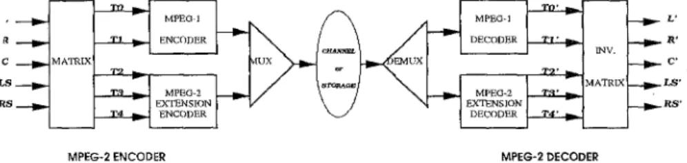
o information from five multichainnel signals. This implies the provision of compatibility matrices, using adequate inverse matrix coefficients. Figure 1
MPEG-2 ENCODER MPEG-2 DECODER
Figure 1: Backward Compatible for MPEG-2 Audio Codec
among the five audio channels (L, R, C, LS, RS), the two basic channels (TO, T1) and the three extended channels (T2, T3, T4).
A matrixing operation of five channels in encoder yields two compatible stereo signals, LO, and RO. The signals LO and RO are transmitted in MPEG- 1 format in transmission channels TO and T1. Channels T2, T3, and T 4 together form the multichannel extension signal. It is realised by exploiting the ancillary data field of the MPEG-2 data structure for the provision of the multichannel extended channels, as described in Figure 2.
3
Decoder
Implementation
Strategy
The basic block diagram for MPEG-2 audio decoder is shown in Figure 3. First, the deformating process extracts the coded samples, multichannel pro- cessing modes and other control information. These samples are interpreted into quantized samples in inverse quantization. Then, multichannel processor reconstructs subband samples with quantized samples and other multichan- nel related information. Last, a set of 32 scaled-up subband samples are fed into the subband synthesis filter t o reconstruct the five channel output PCM audio signals.
3.1
Computation
Analysis
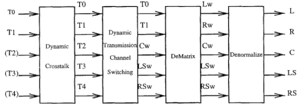
MPEG-2 audio decoding algorithm contains highly overheads of computation and complex control. Referring to the computation, Table 1 illustrates the most common arithmetic operations in MPEG-2 audio decoding. Each decod- ing classification block can be further divided into some functions. In inverse quantization (IQ), coded samples can be reconstructed into the multichan- nel samples by requantization and rescalizaiton functions. In multichannel processing (MC), the subband samples can be reconstructed by four main functions, such as dynamic crosstalk, dynamic transmission channel switch- ing, dematrix and denormalization. The MC processing is described in Figure
Header Ancillary Data 2
I CRC SCFSI I
I
BAL SCF Subband Sample Anclllary Data 1I
I I I I I I I I I I I Classification Functioin IQ Requantizakion MC Dynamic Crossstalk Rescalization DTCS Dematrixing Denormaliz it t' ion
Syn. Subband IMDCT
IPQMF
, )
LO/RO Basic stereo ..(' Multichannel j
extension :
Required Arithmetic Operations
y = ( x
+
a)b y = a x yi=
sixj yi=
xj y = xi - x3 - X k y = a x y = ax+
b,
y=
xi
cixi y = a x , y = C j w ; MC-Header1 MC-CRC MC-SCFSI MC-Subbqnd Sample
I
L MC-BAL I MC-SCF I 1 1 I I I 1 t b I I I I I-I
' ( - - - Multichannel extensionFigure 2: Data Structure of MPEG-2 Multichannel Bit Stream
Data
Coded Data
T1 To
3
Stage Computation Control Memory Requirement
Pre-processing few complex few
Post-processing large simple large
(IQ I MC) (7%) - (Synthesis Subband) (93%) I Crosstalk Dynamic ransmissioi Channel Switching L R C LS RS
Figure 4: Multichannel Decoding Processing
Table 2: Distinctions Between Pre-processing and Post-processing stage
inverse Modified Discrete Cosine Transform (IMDCT), and implements the polyphase synthesis subband operations in the inverse Pseudo Quadrature Mirror Filter (IPQMF).
3.2
Decomposition of Decoding Processing
A similar analysis of the arithmetic operations in decoding algorithm shows that multiplication and addition are the most common operations. Such as the IMDCT module, a 32 X 64 transform can be realized by the multiplier- accumulate computation(MAC) directly. Also, a window operation with 512- t a p FIR is realized in IPQMF as the MAC operations. If a operation is defined as d a t a access, store, add, shift, or multiply in most DSP applications, these two modules of synthesis subband occupy about 93% computation power of the whole decoding process.
Although most of the computation amount in whole decoding process are focused on synthesis subband filter, theses computation takes the advantages of simple control and regular data flow. Besides, the inverse quantization (IQ) and multichannel processing (MC) only occupy 7% computation amount of
whole decoding process, but induce complex control and irregular data flow. In order to improve the system performance, we develop an efficient im-
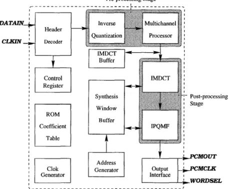
Window Buffer Post-processing Stage I Interface I WOiWSEL
Figure 5: Overall Architecture Diagram
may be divided into two distinct stage, referred to here as pre-processing and post-processing stage. Pre-processing stage mainly includes the IQ and MC
processing. Post-processing stage refers to the synthesis subband filter. The distinctions between these two stages are illustrated in Table 2.
For pre-processing stage, it wes few computation power of whole decoding process and a relatively small amount of memory. But complex control will be induced, especially in MC decoding processor.
In contrast with the pre-processing stage, post-processing stage uses large computation power of whole decoding process with a simple and regular con- trol, and a large amount of memory for synthesis window buffer. Thus, the pre-processing stage, especially for the multichannel processor, may be im- plemented by an efficient architecture with smooth data arrangement and efficient flow control. The post-processing stage may be implemented by high performance data path with full!y hardware utilization. The architecture de- sign issues for two processing stages will be introduced in next section.
~ to IMDCT huffer
ADD/
-
Reg Reg RegSUB
+
____ Reg Reg Reg
I
I
Reg Re R e
m
I,
%
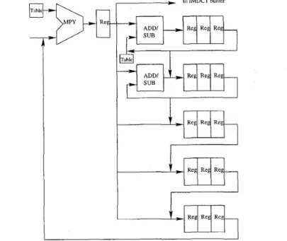
R e Re RegFigure 6: Efficient Architecture for Pre-processing Stage
4
Architecture Design
According to the approaches for simplicity and low-cost design, we take use of the dedicated hardware approach (ASIC), which provides a more efficient VLSI solution than commercial programmable design do.
Figure 5 describes the overall architecture diagram of our proposed design. It includes 5 primary modules called: header decoder, inverse quantization, multichannel processor, IMDCT module and IPQMF module. The header de- coder interprets header information from audio bit-stream (DATAIN), then extracts multichannel processing modes and some control informations to store in control register. The pre-processing stage performs the inverse quan- tization and multichannel processing operations t o reconstruct the subband samples. These samples are stored in IMDCT buffer. T h e IMDCT buffer, a
ping-pong mode buffer, can be viewed as a output buffer of the pre-processing stage and the input buffer of the post-processing stage. A synthesis window buffer is supported for the implementation of synthesis subband functions in post-processing stage.
4.1
Architecture Design
for
Pre-processing Stage
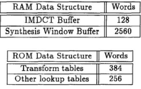
Table 3: Dmecoder Memory Summary (ata Structure I T C T Buffer Words 128 -Window Buffer 2560
I
-3ta Structure
11
WordsJ
Transform tableslar data flow for multichannel processing. Three registers per one channel is supported for Layer-2 decoding applications [l]. Only one multiplier and two adder/subtractor is used as a two-stage pipelined structure. Some quantized, rescalized, dematrixing and denormalization coefficients are stored in tables. This architecture takes the advantages of the efficient control strategy, and the smooth d a t a flow without frequently memory access.
4.2
The synthesis subband filter opleration take a large overheads of computation in whole decoding process. Thus it is necessary to reduce the computation amount by some fast algorithrn [3]. We adopt the modified fast IMDCT algorithm to reduce the multiplier-accumulate computation into 1/4 amount of the I S 0 suggestion method. Moreover, the required size for the synthesis window buffer in which the QMF data V stored can be reduced only t o 512 words per channel, instead of the original size of 1024 words per channel. The decoder memory is summarized in Table 3.
The IMDCT and IPQMF modules, divided from synthesis subband filter, mainly contain a n identical multiplier-accumulator (MAC) respectively. The architecture of post-processing is more simple and regular than pre-processing stage. Also, by taking into account efficiency in hardware utilization and high performance, two identical MAC: units perform a twGstage pipelined of struc- ture as illustrated in Figure 7. With two identical pipeline stage of 512 clock cycles, 100% hardware utilization in post-processing can be feasible. This architecture is based on the goal for simplicity and low-cost design, without any external memory support.
time L-0 IPQMF module R-0 C-0 Ls-0 Rs-0 L-1 R-1 C-1
_ _ _ _
-
5 12 clock cyclesFigure 7: Two Stage Pipelined Reservation Table for Synthesis Subband Filter
5
Conclusions
We have designed an MPEG-2 audio decoder. Based on our design strategy, we divided the decoder into pre and post-processing stages. According to the detail discussions and hardware considerations, these two stages can be im- plemented in distinct approaches. Besides, an efficient multichannel processor architecture for pre-processing stage is proposed. The decoder is developed
for the goals of simplicity and low-cost design.
References
[l] MPEG, "IS0 CD 11172-3: coding of moving pictures and associated audio for digital storage media at up t o about 1.5 Mb/s", Nov 1991.
[2] MPEG, "IS0 CD 13818-3: coding of moving pictures and associated audio for'digital storage media at up to about 1.5 Mb/s", Nov 1994.
[3] T. H. Tsai, T. H. and Chen, and L. G. Chen, "An MPEG audio decoder chip," IEEE Transactions o n C o n s u m e r Electronics., vol. 41, no. 1, pp. 89-96, Feb 1995.