Tunnelling in Taiwan
Assessment of damage in mountain tunnels due to the
Taiwan Chi-Chi Earthquake
W.L. Wang
a, T.T. Wang
b,U, J.J. Su
a, C.H. Lin
a, C.R. Seng
a, T.H. Huang
ba
United Geotech Inc., Taipei, Taiwan, ROC
bDepartment of Ci¨il Engineering, National Taiwan Uni¨
ersity, 1 Section 4 Roose¨elt Road, Taipei, Taiwan, ROC Received 15 March 2001; received in revised form 10 August 2001; accepted 14 August 2001
Abstract
Tunnels, being underground structures, have long been assumed to have the ability to sustain earthquakes with little damage. However, investigations of mountain tunnels after the Chi-Chi Earthquake in central Taiwan revealed that many tunnels suffered significant damage to various extents. This work describes the findings of a systematic assessment of damage in the mountain tunnels in Taiwan after the earthquake. It was found that among the 57 tunnels investigated 49 of them were damaged. The damage patterns are summarized based on the characteristics and the distribution of the lining cracks. This systematic investigation, involving geological conditions, design documents, construction and maintenance records of these tunnels, has been conducted to assess the potential factors that may have influence on the various damage patterns and the earthquake loading for tunnels. The results show that the degree of damage is associated with the geological condition and structural arrangement of the tunnel. A tunnel passing through a displaced fault zone will definitely suffer damage. The extent of geological weak zones, distance from the epicenter, and the existence of a slope face are also significant influencing factors. The seismic capacity of the tunnel is influenced by its structural arrangement, type of lining, invert setup, lining reinforcement, and other parameters.䊚 2001 Elsevier Science Ltd. All rights reserved.
Keywords: Tunnel damage; Earthquake; Lining cracks
1. Introduction
Mountain tunnels, being situated deep within rock layers, have generally been assumed to be sustainable against damage from earthquakes. Previous studies have found earthquake damage in tunnels to be local-ized at sections with two important characteristics: those running through displaced faults, which were damaged by shear forces that developed during the
Ž
earthquake, and those near surface slopes especially at
UCorresponding author. Tel.: 2746-6777; fax:
q886-2-2364-5734.
Ž .
E-mail address: [email protected] T.T. Wang .
.
portal sections , which were damaged owing to slope Ž
failures Dowding and Rozen, 1978; Yoshikawa, 1981; . Sharma and Judd, 1991; Asakura and Sato, 1996, 1998 . Most of the design codes relating to earthquake mitiga-tion for mountain tunnels are currently designed for use at portals and sections near slope surfaces, and seldom for other sections, including deeper mined parts and areas near intersections. Nevertheless, the Chi-Chi Earthquake inflicted significant damage on many tun-nels in central Taiwan, such as cracking, spalling of concrete lining and deformation of steel reinforcement. This damage provides sufficient evidence to suggest that the effects of earthquakes on tunnels should be further studied.
To study the damage influencing factors, the results
0886-7798r01r$ - see front matter 䊚 2001 Elsevier Science Ltd. All rights reserved. Ž .
Chi-Chi Earthquake were presented in this paper. For each tunnel, the damage patterns are examined on the basis of crack mapping results, and the degree of damage was assessed based on its functionality after the earthquake. Tunnel damage, geological and geotechnical conditions and tunnel structural charac-teristics are systematically investigated to evaluate the factors influencing tunnel damage in an earthquake. This paper also discusses the influence of seismic ef-fects on tunnel engineering.
2. Brief description of the Chi-Chi Earthquake
On 21 September 1999, at 01.47 h local time, a strong earthquake with a magnitude of 7.3 on the Richter scale occurred near the town of Chi-Chi in
Ž .
central Taiwan N23.78⬚, E120.84⬚ , at a depth of ap-proximately 7.5 km. The island suffered catastrophic damage during the earthquake, with 2375 lives being lost, over 10 000 people being injured and more than 30 000 buildings collapsed.
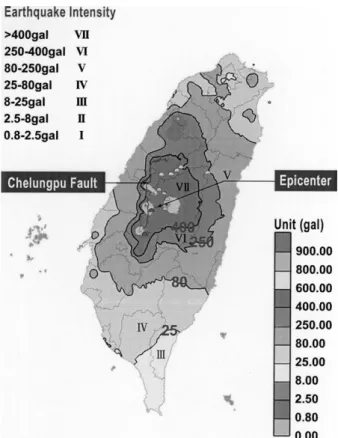
The Chi-Chi earthquake resulted from the reactiva-tion of the Chelungpu Fault. The fault was long ago identified as a thrust fault, running in a N᎐S direction for a total length of 60 km, while dipping eastward at an angle of 30⬚ or less. However, visually identified surface ruptures following the earthquake indicated that the fault is more extensive. It has a total length of 85 km, including newly formed branches at the north-ern tip of the fault, as shown in Fig. 1. This growth of the fault represents the largest known onshore thrust-faulting event of the 20th century.
Geologically, the fault is easily identifiable. The
for-Fig. 1. Intensity of Chi-Chi Earthquake felt at different locations in
Ž .
Taiwan after National Central University, 2001 .
mation on the east of the fault, i.e. the hanging wall, consists of late Pliocene Chinshui Shale and early Pleistocene shaley Cholan Formation, while the west of the fault, the footwall, consists of gravelly late Pleis-tocene Toukershan Formation.
The Chi-Chi earthquake caused significant ground
Table 1 Tunnels investigated and their damage types No. Tunnel and Basic information location Tunneling Length Width Lining Distance Distance a Ž. Ž. Method m m to the to Che-epicenter Lung-Pu Ž. Ž. km fault km 1 Shih-Gang Dam, NA TM ᎐᎐ Y ᎐ 0.0 Water conveyance tunnel 2 Highway 8, 13k q 381 T 2 0 6.5 N 35.1 12.0 3 Highway 8, 27k q 710 T 3 0 6.8 N 38.6 18.6 Li-Lang Tunnel 4 Highway 8, 34k q 668 T 5 0 3.2 Y 44.0 20.1 5 Highway 8, 34k q 775 T 4 1 3.4 Y 44.0 20.1 6 Highway 8, 35k q 908 T 9 0 5.1 Y 44.8 19.8 old Ku-Kuan Tunnel 7 Highway 8, 36k q 908 T 9 0 7.5 Y 44.8 19.8 Ku-Kuan Tunnel 8 Highway 8, 38k q 500 T 150 4.0 Y 45.9 21.5 No.1 old Maa-Ling Tunnel 9 Highway 8, 38k q 500 T 365 5.1 Y 45.8 21.5 No.1 Maa-Ling Tunnel 10 Highway 8, 39k q 075 T 6 0 7.5 Y 46.1 21.6 No.2 Maa-Ling Tunnel 11 Highway 8, 40k q 830 T 245 7.5 Y 46.3 21.6 No.3 Maa-Ling Tunnel 12 Highway 8, 41k q 311 T 100 7.5 Y 47.8 22.1 No.4 Maa-Ling Tunnel 13 Highway 8, 41k q 311 T 100 4.0 Y 47.8 22.1 No.4 old Maa-Ling 14 Hig hway 8, 42k q 573 T 1 0 6.5 N 48.3 23.0 15 Highway 8, 43k q 040 T 1 5 6.5 N 48.3 23.0 16 Highway 8, 45k q 266 T 3 2 6.5 Y 48.5 22.8 17 Highway 14, 37k q 405 T 150 7.5 Y 19.7 12.0 Shuang-Fu Tunnel 18 Highway 14, T 182 7.5 Y 19.8 12.2 Ž. 37k q 981 L Gang-Lin Tunnel 19 Highway 14, T 249 7.5 Y 19.8 12.2 Ž. 38k q 000 R Gang-Lin Tunnel
Ž. Table 1 Continued No. Tunnel and Basic information location Tunneling Length Width Lining Distance Distance a Ž. Ž. Method m m to the to Che-epicenter Lung-Pu Ž. Ž. km fault km 20 Highway 14, T 158 7.5 Y 19.0 13.8 Ž. 39k q 921 L Yu-Ler Tunnel 21 Highway 14, T 158 7.5 Y 19.0 13.8 Ž. 39k q 921 R Yu-Ler Tunnel 22 Highway 14, 45k T 120 7.5 Y 15.9 17.5 q 182 Pei-Shan Tunnel 23 Highway 14, T 129 7.5 Y 17.1 20.4 Ž. 48k q 616 L No.1 Kuan-Yin Tunnel 24 Highway 14, T 129 7.5 Y 17.1 20.4 Ž. 48k q 616 R No.1 Kuan-Yin Tunnel 25 Highway 14, T 123 7.5 Y 17.5 20.8 Ž. 48k q 787 L No. 2 Kuan-Yin Tunnel 26 Highway 14, T 123 7.5 Y 17.5 20.8 Ž. 48k q 787 R No.2 Kuan-Yin T unnel 27 Highway 14, 49k q T 252 7.5 Y 17.6 21.2 Ž. 253 L No. 3 Kuan-Yin Tunnel 28 Highway 14, T 252 7.5 Y 17.6 21.2 Ž. 49k q 253 R No. 3 Kuan-Yin Tunnel 29 Highway 16, T 238 4.8 Y 6.1 5.5 Chi-Chi Tunnel 30 Highway 16, NA TM 580 7.5 Y 6.4 5.3 Ž. New Chi-Chi Tunnel L 31 Highway 16, NA TM 515 7.5 Y 6.4 5.3 Ž. New Chi-Chi Tunnel R 32 Highway 21, NA TM 462 7.5 Y 14.2 21.8 Ž. 54k q 326 L Da-Yuan Tunnel
Ž. Table 1 Continued No. Tunnel and Basic information location Tunneling Length Width Lining Distance Distance a Ž. Ž. Method m m to the to Che-epicenter Lung-Pu Ž. Ž. km fault km 33 Highway 21, NA TM 444 7.5 Y 14.2 21.8 Ž. 54k q 326 R Da-Yuan Tunnel 34 Highway 21, NA TM 185 7.5 Y 8.5 19.9 Ž. 66k q 940 L Shue-Sir Tunnel 35 Highway 21, NA TM 185 7.5 Y 8.5 19.9 Ž. 66k q 940 R Shue-Sir Tunnel 36 Highway 21A, 17k q 303 T 128 7.5 Y 9.3 20.2 No. 1 Huan-Hu Tunnel 37 Highway 21A, 17k q 253 T 6 1 7.5 Y 9.3 20.2 No. 2 Huan-Hu Tunnel 38 Highway 149, NA TM 505 7.0 Y 31.1 7.0 Tsao-Ling Tunnel 39 Highway 149, T 5 2 7.5 N 32.0 3.7 Ching-Shue Tunnel 40 Tou-6 highway, T 100 6.5 Y 15.5 7.2 No. 1 Tu-Cheng Tunnel 41 Tou-6 highway, T 290 6.4 Y 15.3 7.6 No. 2 Tu-Cheng Tunnel 42 Tou-6 highway, T 140 5.3 Y 15.2 7.8 Ž. Shuang-Lung Tunnel E 43 Tou-6 highway, T 9 0 5.3 Y 15.2 7.8 Shuang-Lung Ž. Tunnel W 44 Tou-6 highway, T 8 0 4.5 Y 15.2 7.8 No. 1 Shuang-Tung Tunnel 45 Tou-6 highway, T 120 4.5 Y 15.2 7.8 No. 2 Shuang-Tung Tunnel 46 Chi-Chi line railway, T 350 5.0 Y 6.1 5.5 No. 1 tunnel 47 Chi-Chi line railway, T 1400 5.0 Y -11 1 No. 2 tunnel 48 Chi-Chi line railway, T 250 5.0 Y 4.5 15.9 No. 3 tunnel 49 Chi-Chi line railway, T 150 5.0 Y 5.5 16.4 No. 5 tunnel
Ž. Table 1 Continued No. Tunnel and Basic information location Tunneling Length Width Lining Distance Distance a Ž. Ž. Method m m to the to Che-epicenter Lung-Pu Ž. Ž. km fault km 50 Da-Kuan power station, T ᎐᎐ Y 8.5 19.9 headrace tunnel 51 New Tien-Lun NA TM 10 600 5.0 Y 4 0 18.6 power station, headrace tunnel 52 Mountain line railway, NA TM 7540 9.1 Y 5 5 11.1 No. 1 San-I Tunnel 53 Mountain line railway, NA TM 260 9.1 Y 5 0 10.1 No. 2 San-I Tunnel 54 Mountain line railway, NA TM 520 9.1 Y 4 9 10.1 No. 3 San-I Tunnel 55 Mountain line railway, NA TM 455 9.1 Y 4 9 10.1 No. 4 San-I Tunnel 56 Old mountain line T 230 5.0 Y 5 9 14.5 railway, No. 1 San-I Tunnel 57 Old mountain line T 730 5.0 Y 5 8 13.1 railway, No. 2 San-I Tunnel No Tunnel and Damage description Damage classification b location Portal Sheared Slope Lining Concrete Water Exposed Lining Pavement Rockfalls Overall Mined Portals failure off lining failure cracks lining inrush reinforce displaced cracks in section induced spalling ment unlining tunnel section collapse 1 Shih-Gang Dam, 6 C Water conveyance tunnel 2 Highway 8, 13k q 381 6 AA A 3 Highway 8, 27k q 710 AA A Li-Lang Tunnel 4 Highway 8, 34k q 668 66 BA B 5 Highway 8, 34k q 775 66 BA B 6 Highway 8, 35k q 908 66 6 BA B old Ku-Kuan Tunnel 7 Highway 8, 36k q 908 66 BA B Ku-Kuan Tunnel 8 Highway 8, 38k q 500 66 6 6 CB C No.1 old Maa-Ling Tunnel
Ž. Table 1 Continued b No Tunnel and Damage description Damage classification location Portal Sheared Slope Lining Concrete Water Exposed Lining Pavement Rockfalls Overall Mined Portals failure off lining failure cracks lining inrush reinforce displaced cracks in section induced spalling ment unlining tunnel section collapse 9 Highway 8, 38k q 500 66 6 6 6 6 CC C No.1 Maa-Ling Tunnel 10 Highway 8, 39k q 075 6 CA C No.2 Maa-Ling Tunnel 11 Highway 8, 40k q 830 66 CA C No.3 Maa-Ling Tunnel 12 Highway 8, 41k q 311 AA A No.4 Maa-Ling Tunnel 13 Highway 8, 41k q 311 66 6 CC A No.4 old Maa-Ling 14 Highway 8, 42k q 573 6 6 CC C 15 Highway 8, 43k q 040 6 6 BA B 16 Highway 8, 45k q 266 66 CB C 17 Highway 14, 37k q 405 6 AA A Shuang-Fu Tunnel 18 Highway 14, 66 6 6 CA C Ž. 37k q 981 L Gang-Lin Tunnel 19 Highway 14, 66 6 AA A Ž. 38k q 000 R Gang-Lin Tunnel 20 Highway 14, 66 AA A Ž. 39k q 921 L Yu-Ler Tunnel 21 Highway 14, 66 AA A Ž. 39k q 921 R Yu-Ler Tunnel 22 Highway 14, 45k 6 AA A q 182 Pei-Shan Tunnel 23 Highway 14, 6 AA A Ž. 48k q 616 L No.1 Kuan-Yin Tunnel 24 Highway 14, 6 AA A Ž. 48k q 616 R No.1 Kuan-Yin T unnel
Ž. Table 1 Continued b No Tunnel and Damage description Damage classification location Portal Sheared Slope Lining Concrete Water Exposed Lining Pavement Rockfalls Overall Mined Portals failure off lining failure cracks lining inrush reinforce displaced cracks in section induced spalling ment unlining tunnel section collapse 25 Highway 14, 66 AA A Ž. 48k q 787 L No. 2 Kuan-Yin Tunnel 26 Highway 14, 66 AA A Ž. 48k q 787 R No.2 Kuan-Yin Tunnel 27 Highway 14, 49k q 66 6 BA B Ž. 253 L No. 3 Kuan-Yin Tunnel 28 Highway 14, 66 AA A Ž. 49k q 253 R No. 3 Kuan-Yin Tunnel 29 Highway 16, 66 AA A Chi-Chi Tunnel 30 Highway 16, 6 AA A Ž. New Chi-Chi Tunnel L 31 Highway 16, 66 6 CC A Ž. New Chi-Chi Tunnel R 32 Highway 21, 6 AA A Ž. 54k q 326 L Da-Yuan Tunnel 33 Highway 21, 6 AA A Ž. 54k q 326 R Da-Yuan Tunnel 34 Highway 21, 6 AA A Ž. 66k q 940 L Shue-Sir Tunnel 35 Highway 21, AA A Ž. 66k q 940 R Shue-Sir Tunnel 36 Highway 21A, 17k q 303 AA A No. 1 Huan-Hu Tunnel 37 Highway 21A, 17k q 253 AA A No. 2 Huan-Hu Tunnel 38 Highway 149, 66 6 6 CB C Tsao-Ling Tunnel 39 Highway 149, 66 6 CC C Ching-Shue Tunnel 40 Tou-6 highway, 66 AA A No. 1 Tu-Cheng Tunnel
Ž. Table 1 Continued b No Tunnel and Damage description Damage classification location Portal Sheared Slope Lining Concrete Water Exposed Lining Pavement Rockfalls Overall Mined Portals failure off lining failure cracks lining inrush reinforce displaced cracks in section induced spalling ment unlining tunnel section collapse 41 Tou-6 highway, 66 BB A No. 2 Tu-Cheng Tunnel 42 Tou-6 highway, 66 BB A Ž. Shuang-Lung Tunnel E 43 Tou-6 highway, 6 AA A Shuang-Lung Ž. Tunnel W 44 Tou-6 highway, 66 6 BB B No. 1 Shuang-Tung Tunnel 45 Tou-6 highway, 66 AA A No. 2 Shuang-Tung Tunnel 46 Chi-Chi line railway, 6 AA A No. 1 tunnel 47 Chi-Chi line railway, 6 AA A No. 2 tunnel 48 Chi-Chi line railway, 6 BB B No. 3 tunnel 49 Chi-Chi line railway, 6 BB B No. 5 tunnel 50 Da-Kuan power station, 66 CC A headrace tunnel 51 New Tien-Lun 66 6 CC A power station, headrace tunnel 52 Mountain line railway, 66 6 6 CC A No. 1 San-I Tunnel 53 Mountain line railway, AA A No. 2 San-I Tunnel 54 Mountain line railway, AA A No. 3 San-I Tunnel 55 Mountain line railway, AA A No. 4 San-I Tunnel 56 Old mountain line 66 AA A railway, No. 1 San-I Tunnel 57 O ld mountain line 66 AA A railway, No. 2 San-I Tunnel a Tunnelling method: T means traditional tunneling method, NATM means New Austria Tunneling Method.
Fig. 3. Tunnel locations relative to Chelungpu thrust fault.
deformation. GPS survey results indicated that an area east of the fault with a width of approximately 15 km was displaced north-westwards, with a maximum
hori-Ž
zontal displacement of 9.06 m 10 m horizontal dis-.
placement was measured on the ground , and vertically uplifted by approximately 9.8 m at the Shihkang Dam, near the north tip of the fault line. Fig. 1 shows the
Ž .
surface rupture and peak ground acceleration PGA contour caused by the earthquake.
3. Damage to mountain tunnels
Following the earthquake, a systematic investigation was conducted on 57 tunnels located in central Taiwan. Firstly, quick visual inspections were performed within
a couple of days of the earthquake to gather prelimi-nary information on tunnel damage. Detailed surveys were then performed for tunnels that were significantly damaged, using lining crack mapping, photo recording,
Ž and measuring of the major crack characteristics in-cluding width, depth and relative displacement
direc-.
tion . Non-destructive inspection methods, such as
Ž .
ground penetration radar GPR , were also used in several severely damaged tunnels. Fig. 2 indicates the locations of the investigated tunnels and the intensity of the earthquake on the ground surface.
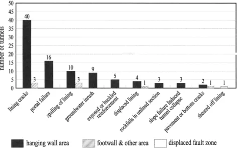
Various types of damage were observed, including lining cracks, portal failure, concrete lining spalling, groundwater inrush, exposed and buckled reinforce-ment, displaced lining, rockfalls in unlined sections, lining collapses caused by slope failure, pavement or
a,b
Tunnel classification Damage level Damage description Traffic strategy
No A No damage No damage detectable by visual inspection. Normal
immediate A Slight Light damage detected on visual inspection, no operation
c c
Ž .
danger effects on traffic w -3 mm, l -5 m .
Ž .
Dangerous B Moderate Spalling, cracking of linings w)3 mm, l)5 m , Operable with exposed reinforcement, displacement of segmental regulations joints, leaking of water.
Some disruption to traffic.
Dangerous C Severe Slope failure at openings, collapse of main tunnel Not structure, up heave or differential movement of operable road and road shoulder, flooding, damaged
ventilation and lighting system in long tunnels. Total disruption of traffic.
a
Ž
Classification of a tunnel is based on its functionality traffic condition for road tunnels, ability to withstand water pressure for water .
conveyance tunnels and extent of damage in the tunnel.
bClassification of a tunnel should be based on the least safe section being assessed to be conservative. c
wswidth of crack, lslength of crack.
bottom cracks, and sheared off lining. Table 1 lists the basic information and damage conditions of the investi-gated tunnels.damage suffered by mountain tunnels following the earthquake.
Ž .
Huang et al. 1999 suggested assessing the degree of damage to a tunnel based on its functionality after an earthquake. Considering the potential hazard to vehi-cles, the degree of damage can be evaluated according to the width and length of cracks in mined sections of typical traffic tunnels, as presented in Table 2. Mean-while, in this paper the degree of damage to the portal section can be accessed by the stability of the slope above the tunnel. For simplicity, the same damage evaluation standards are also adopted herein for water conveyance tunnels. Among the 57 tunnels investi-gated, only 8 are classified as totally undamaged, while the other 49 tunnels suffered various degrees of damage, as summarized in Table 1. Table 3 lists the degree of damage to tunnels in different categories. The tunnels passing through the displaced fault zone suffered catastrophic damage, and the lining was
sheared off. Meanwhile, for the 50 tunnels in the
Ž .
hanging wall group, 5 tunnels 10% are classified as
Ž .
undamaged, 21 tunnels 42% were lightly damaged, 11 Ž22% moderately damaged and 13 26% severely da-. Ž . maged. Finally, for the 6 tunnels in the footwall and
Ž . Ž .
other areas, 3 50% suffered no damage at all, 2 34%
Ž .
were lightly damaged and 1 16% was severely da-maged. Evidently, the tunnels located in the hanging wall area suffered more damage than those in the footwall area.
4. Classification of damage patterns
Numerous damage conditions were observed in the
Ž .
tunnels United Geotech, Inc., 1999a,b , and some of the major patterns with significant characteristics are illustrated below.
4.1. Sheared off lining
All buildings, bridges, roads, tunnels or other
struc-Table 3
Ž .
Damage of mountain tunnels caused by Chi-Chi Earthquake after Wang et al., 2000
Location No. of tunnels Tunnel Damage Tunnel Damaged Damaged in
assessed classification level damaged in portal mined section
Displaced 1 A Slight ᎐ ᎐ ᎐
fault zone 1 B Moderate ᎐ ᎐ ᎐
1 C Severe 1 ᎐ 1
Hanging 50 A Slight 26 32 35
wall area 50 B Moderate 11 9 8
50 C Severe 13 9 7
Footwall 6 A Slight 2 3 2
and other 6 B Moderate ᎐ ᎐ ᎐
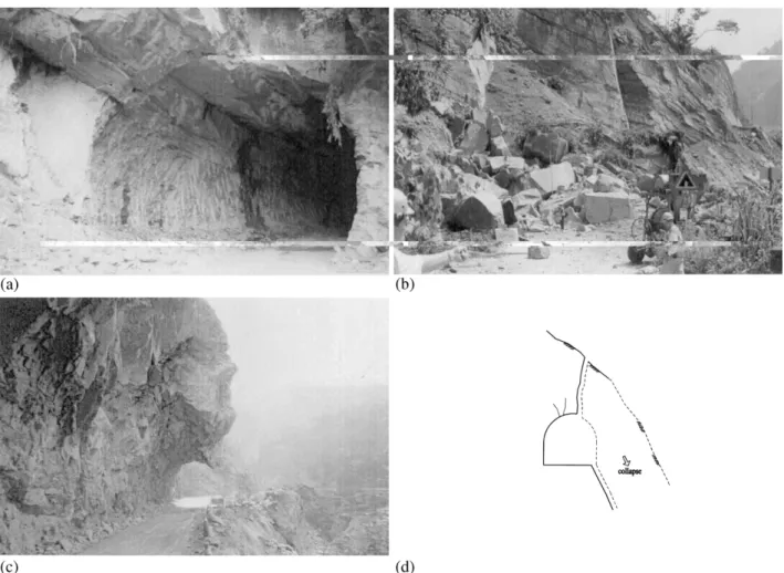
stroyed, regardless of their size and stiffness, when the Chelungpu Fault line underwent shearing. The Shih-gang Dam and its water conveyance tunnel are the best examples of this type of failure. Investigations by Chang
Ž .
and Chang 2000 revealed that this gravitational type Shihgang Dam was displaced 7.8 m vertically and 7.0 m horizontally towards the north, destroying the dam’s water retaining function. The dam’s water conveyance tunnel was also sheared off at a point 180 m down-stream from the inlet because of the displaced fault. The tunnel was separated roughly 4 m vertically and 3 m horizontally, as displayed in Fig. 5a, causing the tunnel to fail. Furthermore, severe spalling of the con-crete lining and cracks developed along the tunnel, as illustrated in Fig. 5b.
4.2. Slope failure induced tunnel collapse
When surface slopes fail during an earthquake, tun-nels can be damaged by the failure surface at sections near the slope face. Fig. 6a᎐c illustrate two representa-tive cases from tunnels located at Sta. 42kq573 of Highway No. 8 and the Chingshue Tunnel of Highway No. 149A. The damage patterns are presented Fig. 6d.
Ž .
Fig. 5. Damage patternᎏ sheared off lining. a sheared off damage Ž .
at the water conveyance tunnel of Shih-Gang Dam; b sketch of sheared off lining damage.
Ž . Ž .
Fig. 6. Damage patternᎏ slope failure induced tunnel collapse. a photo of Chi-Shue Tunnel before Chi-Chi Earthquake; b photo f Chi-Shue
Ž . Ž .
Ž . Ž .
Fig. 7. Damage patternᎏ longitudinal cracks. a sketch of longitudinal cracks damage; b typical mapping result of singular crack at the vault
Ž . Ž .
of the crown; c typical mapping result of symmetrical cracks; d typical mapping result of non-symmetrical cracks.
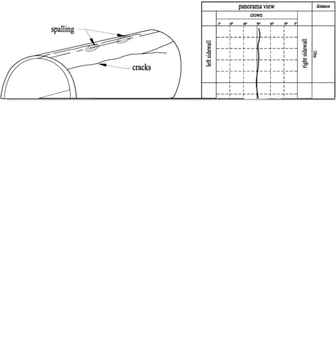
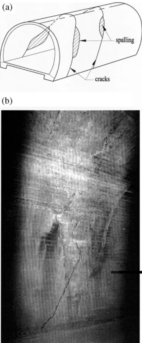
4.3. Longitudinal cracks
Longitudinal cracks in the concrete lining were de-veloped in some tunnels, and were generally extended. The crack length often exceeds the diameter of the tunnel, as illustrated in Fig. 7a. This damage pattern can be further classified into three types, singular crack at the vault of the crown, symmetrical cracks, and non-symmetrical cracks, as shown in Fig. 7b᎐d. Most of the singular cracks and symmetrical cracks are of the open and non-sheared types. The No. 1 San-I railway tunnel, New Chi-Chi Tunnel on Highway No. 16 and the headrace tunnel of New Tienlun power station are the most representative examples of this type of da-mage.
4.4. Trans¨erse cracks
Cracks in the concrete lining also developed perpen-dicular to the direction of tunnel axis, as illustrated in Fig. 8. These cracks were generally observed above the road, and were characterized by the spalling or relative displacement of the lining. The No. 1 San-I railway tunnel and the No. 1 Maaling Tunnel on Highway No. 8 are the most representative examples of this kind of damage.
4.5. Inclined cracks
Singular cracks inclined at 30᎐60⬚ to the horizontal develop in concrete lining at one side of the tunnel and
Fig. 8. Damage patternᎏ transverse cracks.
generally terminating at the segmental joints, as illus-trated in Fig. 9. Damage of this type was found in the No. 1 San-I railway tunnel.
4.6. Extended cross cracks
Inclined cracks in the concrete lining develop at variable inclinations and run continuously, possibly crossing segmental joints, along the concrete lining segments and around the tunnel, as illustrated in Fig. 10a. The No.1 Shuangtung Tunnel, shown in Fig. 10b, and the West Shuanglung Tunnel of Tou-6 highway are typical examples of this kind of damage.
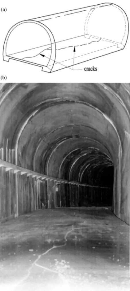
4.7. Pa¨ement or bottom cracks
Cracking of the pavement or the bottom of the tunnel usually runs continuously over a long distance, as shown in Fig. 11a, such as in the Shuanglung Tunnel of the Tou-6 highway. More serious damage may also occur in the form of up heaving, such as the adit of the No.1 San-I railway tunnel, as shown in Fig. 11b.
4.8. Wall deformation
Fig. 12a shows tunnel damage caused by significant inward deformation of the sidewalls. The deformation caused numerous cracks in the concrete lining on the inner face of the sidewalls and collapse of the side ditch, such as in the adit of the No.1 San-I railway tunnel shown in Fig. 11b and Fig. 12b.
Fig. 9. Damage patternᎏ inclined cracks.
Ž .
Fig. 10. Damage pattern ᎏ extended cross cracks. a sketch of Ž .
extended cross cracks; b extended cross cracks observed in No. 1 Shuang-Tung Tunnel.
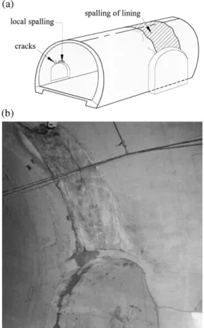
4.9. Cracks that de¨elop near opening
It is very common to see cracks developed near an opening such as electronic niche, fireplug and fire extinguisher niche, refuge and so on. These cracks illustrated in Fig. 13a are usually localized and limited to a few meters. However, as those openings become large and are arranged symmetrically, the cracks can extend from both sides and join together. The collapse at the large refuges of the No. 1 San-I railway tunnel is an example, as shown in Fig. 13b.
5. Study of the possible influences related to tunnel damage
Based on the above damage patterns, possible causes of tunnel damage are investigated. For each damaged tunnel, relevant geological investigation reports, design documents and details on construction and mainte-nance were collected. Details of each section of the
Ž . Fig. 11. Damage patternᎏ pavement or bottom cracks. a sketch of
Ž .
pavement or bottom cracks; b bottom cracks observed in the adit of No. 1 San-I railway tunnel.
damaged tunnels were systematically investigated to examine possible factors controlling the occurrence of a certain type of damage. Table 4 illustrates an exam-ple of such an investigation, focusing on the eight damaged sections in the No. 1 San-I railway tunnel.
The major factors associated with increased damage include: tunnel being located adjacent to surface slopes or portals, tunnel running through faults, absence of concrete lining, unusual or unfavorable concrete lining conditions, steep sidewalls, absence of invert, etc. These factors are listed in Table 5 corresponding to the damage patterns, and can be broadly classified into three major categories, as discussed below.
5.1. Earthquake intensity at each tunnel
The intensity of seismic force experienced by each tunnel differs owing to their different distances from the displaced fault zone and the epicenter of the earthquake. The distance to the ground surface or to nearby slopes also influences the seismic effect. Seismic waves propagate in the ground and lose energy because of dispersion and ground resistance, causing tunnels to
displaced fault zone or the epicenter. Additionally, when seismic waves reach the ground surface, they release energy due to reflection or refraction, and thus tunnels near the surface, and especially those near slope faces, will absorb a greater seismic energy.
5.2. Condition of the surrounding ground
Most mountain tunnels run through very hard ground, and a few tunnels pass through the displaced fault zone and fractured zones. Seismic waves propa-gate faster in hard and dense materials, and thus less energy will be released at places where the tunnels lie in ground that is harder than the tunnel structure, meaning that such tunnels will tend to deform with the ground and suffer less damage. On the other hand, if the tunnels lie in relatively weaker ground they will absorb larger amounts of energy and thus suffer greater damage. Concrete linings can particularly be damaged
Ž .
Fig. 12. Damage patternᎏ wall deformation. a sketch of inward Ž .
deformation of sidewall; b inward deformation of sidewalls in the adit of No. 1 San-I railway tunnel.
Ž .
Fig. 13. Damage patternᎏ cracks nearby the opening. a sketch of Ž .
the cracks nearby the opening; b lining collapse occurred above the refuge of No. 1 San-I railway tunnel.
easily by ground displacement or ground squeeze where soft and hard grounds meet, as soft and hard grounds behave differently during earthquakes.
Any unfavorable events such as cave-in or collapse during tunneling would extend the plastic zone around the tunnel, weaken the surrounding rock and cause excessive vibration when seismic waves pass through. In addition, if the ground has previously experienced ver-tical stress from loosening, plastic stress owing to squeezing, inclined stress or any other weakening processes, tunnels in these areas will suffer greater damage to their concrete linings during an earthquake.
5.3. Seismic capacity of the tunnel
The seismic capacity of tunnels can be assessed by studying the amount of damage sustained, a higher seismic capacity implies the less substantial the da-mages should be. Based on a general review of the 57 tunnels investigated, the seismic capacities of tunnels depend on structural arrangements such as cross-sec-tions and refuge openings, the presence of linings and inverts, the presence of lining reinforcements, lining thickness, and any unusual conditions such as porous
deterioration in the linings.
6. Concluding remarks
Among the 57 tunnels investigated in central Taiwan, 49 tunnels suffered various degrees of damage after the Chi-Chi earthquake. The most and often serious da-mages were found on the east of the Chelungpu fault
Ž .
line hanging wall while damages on the footwall and other areas suffered less. The most severely damaged tunnel sections in the hanging wall are those close to surface slopes or portal openings, while sections with a thick overburden generally suffered less. Nevertheless, however badly the tunnels were damaged, they re-mained relatively unscathed when compared to surface structures.
The extent of damage to tunnel linings was influ-enced by the position of the tunnels in relation to fault zones, ground conditions, and closeness to the epicen-ter and surface slopes. Additionally, the presence and type of lining and lining reinforcement, and any un-usual condition in the linings are also important influ-ence factors. It is difficult in a short time to gather the basic data of a damaged tunnel, especially information on ground conditions, support structure designs and unusual construction events immediately after an earthquake. It is deemed necessary to establish a database of basic information on existing tunnel struc-tures and damage assessment.
To prevent slope failures and fault displacements from damaging tunnels, efforts should be made to avoid passing through active faults and avoid placing tunnels too close to slope faces when planning future tunnels.
The effects of earthquakes on mountain tunnels have seldom been investigated. Up to now, no established methods can be employed for assessing and evaluating tunnel stability during earthquakes, and design codes for earthquake protection in tunneling are lacking. To ensure the functionality of existing tunnels and enable future tunnels to withstand earthquakes, further inves-tigation of the above topics is necessary.
Acknowledgements
The Highway Bureau, MOTC, the Taiwan Railway Administration and RSEA Engineering Corporation are appreciated for providing valuable information on the tunnels, helping in on site investigation, and assist-ing in other various tasks.
Table 4 Ž. Assessment example on damage influencing factors, No. 1 San-I railway tunnel after Wang and Wang, 2000 c Section Location Damage Overburden Adverse Rock mass Construction Auxiliary Convergence Support Opening Concrete a Ž. Ž. type m geological classification hazard method % stress condition Ž. condition RMR Ž. A Approx. 161k q 300 4,9 45 San-I Fault 19 ᎐ Cement grouting 4.1 ᎐ Large Local cavern Ž. zone 5 times refuge existing b Ž. B Approx. 161k q 360 4,9 35 San-I Fault 14 Cave-in Cement grouting 0.3 ᎐ Small Good zone and collapse refuge b Ž. C 161k q 375 ᎐ 410 3,5,9 25 ᎐ 35 San-I Fault 27 ᎐ 30 ᎐᎐ 0.3 8 tons Small Cavern zone in bolts refuge existing Ž. D Approx. 164k q 740 3,9 120 ᎐ 43 ᎐᎐ 1.5 ᎐ Small Local cavern refuge existing Ž. E 164k q 758 ᎐ 810 3,5 125 ᎐ 46 ᎐ 67 ᎐᎐ 1.5 ᎐ 1.8 23.5 MPa in ᎐ Good shotcrete Ž. F 164k q 842 ᎐ 880 3 130 ᎐ 150 ᎐ 19 ᎐ Cement grouting 2. 3 ᎐᎐ Cavern existing Ž. G 165k q 600 ᎐ 660 3,4,5 105 ᎐ 110 ᎐ 35 ᎐ 37 Squeezing Forepoling, 3.6 ᎐ 5.5 ᎐᎐ Cavern and support cement grouting, existing damaged ring excavation and re-supporting Ž. H Approx. 165k q 800 3,9 125 Fractured 28 ᎐᎐ 2.5 ᎐ Small Cavern zone refuge existing a Ž. Ž. Ž. Ž. Ž. Ž. Ž. Damage types: 1 sheared off lining; 2 slope failure induced tunnel collapse; 3 longitudinal cracks; 4 transverse cracks; 5 inclined cracks; 6 extende d cross cracks; 7 pavement Ž. Ž. bottom cracks; 8 wall deformation; 9 cracks nearby the opening. b Section B and C were located close to breakthrough point Sta. 161k q 385, the monitoring results might not reflect the actual tunnel behavior. c The large refuge is 4.5 m in width and 3.5 m in height, the small one is 2.0 m in width and in height, and the excavation size of tunnel is 11 m in width and in hei ght.
a
Possible factors Damage type
1 2 3 4 5 6 7 8 9
c
Passing through displaced fault zones ⵜ
Passing through faults, fractured zone and unfavorable ground condition 䢇 ⵜ
Interface of hard and soft ground ⵜ
Nearby slope surface or portal ⵜ ⵜ ⵜ ⵜ
Unfavorable events such as cave-in, collapse occurred during construction 䢇 䢇 䢇 䢇 Anomaly such as lining cracks occurred before quake 䢇 䢇
b
Poor structural arrangements 䢇 䢇 ⵜ
Absence of lining 䢇
Unreinforced concrete lining 䢇 䢇 䢇 䢇 䢇 䢇 䢇 ⵜ
Steep sidewalls, absence of invert, etc. 䢇 ⵜ ⵜ
Deteriorated lining material 䢇 䢇
Cavity existed behind lining ⵜ 䢇
aDamage types refer to Table 4.
bArrangements such as opening, refuge, etc., especially symmetrically located in both sidewalls. cⵜ presents significant influence,
䢇presents moderate influence.
References
Asakura, T., Sato, Y., 1996. Damage to maintain tunnels in hazard area. Soils Foundations, Special Issue, 301᎐310.
Asakura, T., Sato, Y., 1998. Mountain tunnels damage in the 1995 Ž . HYOGOKEN-NANBU Earthquake. Q. Rep. RTRI 39 1 , 9᎐16. Chang, C.T., Chang, S.Y., 2000. Preliminary inspection of dam works and tunnels after Chi-Chi Earthquake. Sino-Geotechnics 77, 101᎐108.
Dowding, C.H., Rozen, A., 1978. Damage to rock tunnel from Ž . earthquake shaking. J. Geotech. Eng. Div. ASCE 104 GT2 , 175᎐191.
Huang, T.H., Ho, T.Y., Chang, C.T., Yao, X.L., Chang, Q.D., Lee, H.C., 1999. Quick investigation and assessment on tunnel struc-Ž tures after earthquake, and the relevant reinforced methods in
.
Chinese . Report for the Public Construction Commission, Taipei, Taiwan.
National Central University. Department of Earth Science and Insti-tute of Geophysics, 2001. [email protected], Chi-Chi Earthquake Report.
Sharma, S., Judd, W.R., 1991. Underground opening damage from earthquakes. Eng. Geol. 30, 263᎐276.