Mechatronics Concept Designer
White Paper
March 26
th, 2010
Mechatronics Concept Designer confidential Page 2
Table of Contents
1 What is “Mechatronics Concept Designer“? ... 3
1.1 Functional Machine Design ... 3
1.2 Early System Validation ... 4
1.3 Multi-Disciplinary Support ... 5
1.4 Modularity and Reuse ... 7
2 How does “Mechatronics Concept Designer” fit into the design workflow? ... 8
3 Contact ... 10
Mechatronics Concept Designer confidential Page 3
1 What is “Mechatronics Concept Designer“?
1.1 Functional Machine Design
Mechatronics Concept Designer is a solution that transforms the machine creation process into an efficient mechatronics design approach, so it should not be seen as an isolated product. This will significantly reduce the time to market. One of the main instruments in this is the functional model, which forms the foundation to provide an interdisciplinary view of the “mechatronics system” machine.
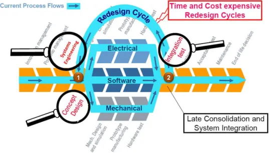
Figure 1: Overall Design Process
Figure 1 shows the typical steps in the design process of a mechatronics system. Many problems in an interdisciplinary design context occur when the disciplines meet each other when the whole system is integrated near the end of the process(2). In many cases, these problems are caused by the loose connection of the detailed design disciplines, including Mechanical, Electrical/Fluid and Software. The different departments do not collaborate to synchronize their work.
Mechatronics Concept Designer will help to lay the foundation for collaboration in detailed design by supporting the early design phase (1) with a functional design approach.
Mechatronics Concept Designer confidential Page 4
Figure 2: The functional data structure
The functional model provides the link between the data management of the different disciplines and the requirements. This enables the traceability
1.2 Early System Validation
of the customer demand data down to the design departments. Further, the functional model provides a supporting structure to come up with initial design concepts and has the features to perform an evaluation of design alternatives.
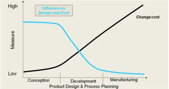
In addition to this, Mechatronics Concept Designer introduces a verification technology that is built on a new simulation engine. This will help to validate concept designs at a very early stage of the
development process. This will save a lot of money since the costs to correct an error increase later in the development process.
Figure 3: Increasing change cost over the maturity of the design
The simulation technology adds value in several ways:
Mechatronics Concept Designer confidential Page 5
• It is easy to use. The modeling of the physical world is very simple. In a few steps you get to a physical definition of your machine concept and your desired machine behavior.
• It covers kinematics, dynamics, collisions, actuators, springs, cams and much more. Everything you need to validate your machine concept.
• It has excellent performance. Just switch it on and you will immediately see your machine design working in real time.
• It is interactive. While the simulation is running you can use your mouse pointer to apply forces to objects on the screen. This will help to anticipate unforeseen behavior and see how the system handles errors.
• It supports material flow with multiple objects. During the simulation you can automatically generate new objects and introduce them to the system, transported by conveyers or processed by an operation.
• It gives you insight into all relevant physical values. Using the “inspector” during the simulation you can click on an object in the scene and will you get its physical runtime parameters like it’s actual position, speed, rotation and much more.
These advantages also come with some restrictions which one has to keep in mind when applying the simulation capabilities of Mechatronics Concept Designer.
• The simulation solver applies simplified equations. Therefore the accuracy of the simulation is not sufficient to make detailed multi-body analyses, such as frequency analysis.
• The collision shapes are approximated. The simulation engine does not provide mesh-to-mesh collision detection, it uses simplified bodies that come close to the original shape. Therefore Mechatronics Concept Designer should not be used for detailed collision analysis of complex, concave shapes.
• Mechatronics Concept Designer does not support flexible bodies (e.g. paper).
• Mechatronics Concept Designer does not simulate the transformation (e.g. melting) or deformation (e.g. material removal of a milling process) of bodies.
1.3 Multi-Disciplinary Support
Following this functional machine design approach, Mechatronics Concept Designer facilitates interdisciplinary concept design up front. The following disciplines can jointly work on a project:
• The mechanical engineer will create the design based on 3D shapes and kinematics.
• The electrical engineer will help to select and position sensors and actuators.
• The automation programmer will use Mechatronics Concept Designer to design the basic logical behavior of the machine, starting with time based behavior and then defining the event based control.
This is not duplicate work because Mechatronics Concept Designer provides output that can be reused for subsequent disciplines.
Mechatronics Concept Designer confidential Page 6
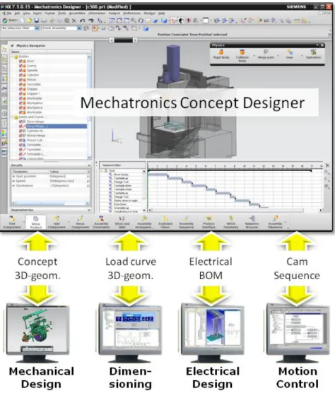
Figure 4: Output of Mechatronics Concept Designer
• Mechanical Design: Mechatronics Concept Designer is based on a CAD platform so it provides all the features that are needed for sophisticated CAD design. It is seamlessly integrated with NX but can export to many other CAD tools such as:
o Catia V5 o ProEngineer o SolidWorks o JT (CAD neutral)
• Dimensioning: Mechatronics Concept Designer can simulate the dynamics of a machine axis and export the load and speed cycle. This can be used in a dimensioning tool like “SINAMICS
MICROMASTER SIZER” to support the selection of the best fitting motor.
This feature is not supported in the current release.
• Electrical Design: During the concept design with Mechatronics Concept Designer, a Sensor and Actuator list will be built. This list can be exported and used in an ECAD tool to help build the layout.
This feature is not supported in the current release.
Mechatronics Concept Designer confidential Page 7
• Automation Design: Mechatronics Concept Designer has the ability to define the Sequence of Operations in a Gantt Chart. This can be exported in a PLCOpen XML format which has been standardized by the AutomationML group. This can be reused for further detailing in the Automation Engineering.
• Motion Control Design: The continuous behavior of synchronized axes can be defined in functions that drive a cam. These functions can be exported in XML and reused in Motion Control Engineering tools for further refinement.
This feature is not supported in the current release.
1.4 Modularity and Reuse
Modularity and Reuse are the keys to maximizing design efficiency. The ability to capture knowledge in components and store them in a library enables the reuse of this knowledge in other projects. This increases design quality because designs are based on already proven concepts and it speeds up development because one does not have to redo tasks which already have been performed.
Mechatronics Concept Designer supports the definition of “functional units” such as those in the VDW Standard “Funktionsbeschreibung”.
Figure 5: Picture from the VDW Standard “Funktionsbeschreibung”
With Mechatronics Concept Designer you can store mechatronics data in one part file (file extension .prt):
• Graphical 3D-data
• Physical data like kinematics, dynamics, …
• Sensors and Actuators with their interfaces
• Cams and functions that are performed by this functional unit
• Operations that are performed by the functional unit
By simply adding this part file to your design you include all of this information in your system. This is the foundation of a step-by-step process to build a library of proven, reusable objects.
Mechatronics Concept Designer confidential Page 8
2 How does “Mechatronics Concept Designer” fit into the design workflow?
As you saw in Figure 1, Mechatronics Concept Designer is designed to support the early design phase that provides the basic machine concept including the mechanical, electrical/fluid and software aspects.
Figure 6 gives an overview of the typical design steps that are performed in the early design phase.
These are supported by the Mechatronics Concept Designer solution with Teamcenter.
Figure 6: Basic workflow supported by Teamcenter (green) and Mechatronics Concept Designer (blue)
Mechatronics Concept Designer’s output will be further refined in the detailed design disciplines. These will rely on existing tools that already exist in the different development departments.
Figure 7: Downstream disciplines that benefit from the data structures provided by Mechatronics Concept Designer and Teamcenter
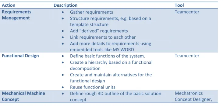
The following table gives an overview of the typical design steps.
Action Description Tool
Requirements
Management • Gather requirements
• Structure requirements, e.g. based on a template structure
• Add “derived” requirements
• Link requirements to each other
• Add more details to requirements using embedded tools like MS WORD
Teamcenter
Functional Design • Define basic functions of the system.
• Create a hierarchy based on a functional decomposition
• Create and maintain alternatives for the functional design
• Reuse functional units
Teamcenter
Mechanical Machine
Concept • Define rough 3D outline of the basic solution concept
Mechatronics Concept Designer,
Mechatronics Concept Designer confidential Page 9
• Assign mechanical implementation objects to functional tree
• Add kinematics and dynamics
(Teamcenter)
Add abstract Actuators
• Add two types of actuators:
o Speed constraint o Position constraint
Mechatronics Concept Designer Define time based
Operations • Define how the actuators are controlled by operations
• Arrange the sequence of operation with a time based notion
• Assign operations to the corresponding functions in the function tree
Mechatronics Concept Designer, (Teamcenter)
Add Sensors • Add sensors that are triggered by collisions of system elements with sensor objects
Mechatronics Concept Designer Define event based
Operations • Define operations that are triggered by events generated by the sensors or other objects in the mechatronics systems (like the position of an actuator)
• Assign operations to the corresponding functions in the function tree
Mechatronics Concept Designer, (Teamcenter)
Refine the mechanical
design • Refine the rough 3D outline of the solution
• Create more detailed geometry
• Assign the geometry to the corresponding functions in the function tree
• Add additional elements like bolts, washers, holes, etc.
The following step is not supported in the current release of Mechatronics Concept Designer.
• Select the best fitting motors based on the simulation results from Mechatronics Concept Designer.
CAD design tool (e.g. NX CAD), (Teamcenter)
SIZER Create the electrical
and fluid layout
The following step is not supported in the current release of Mechatronics Concept Designer.
• Create the electrical and fluid layout based on the sensors and actuators defined in the concept design
• Add further components that are needed to detail the layout plan
• Manage the net list and electrical BOM in Teamcenter
• Assign new items to the function tree
• Perform 3D routing in the CAD tool
• Execute consistency checks to synchronize electrical and mechanical data structures
ECAD tool, 3D routing tool (e.g. NX routing), (Teamcenter)
Develop the
automation software • Export Sequence of Operation in PLCOpen XML from MCD
• Develop PLC code
Automation Engineering Tools, Drive Configuration
Mechatronics Concept Designer confidential Page 10
• Create drive configuration
The following step is not supported in the current release of Mechatronics Concept Designer.
• Define the detailed cams to synchronize multiple axes based on the exported cams from
Mechatronics Concept Designer
Tools
3 Contact
If you have any questions please contact:
Dr. Matthias Lenord I IA PL OAT
Address:
10824 Hope Street Cypress, CA 90630 Phone:
+1.714.952.5380 eMail:
About Siemens PLM Software
Siemens PLM Software, a business unit of Siemens Industry IA (Industry Automation), is a leading global provider of product lifecycle management (PLM) software and services with 4.6 million licensed seats and 51,000 customers worldwide. Headquartered in Plano, Texas, Siemens PLM Software’s open enterprise solutions enable a world where organizations and their partners collaborate through Global Innovation Networks to deliver world-class products and services.
For more information on Siemens PLM Software products and services, visit http://www.siemens.com/plm.