國立臺灣大學電機資訊學院電機工程學研究所 碩士論文
Graduate Institute of Electrical Engineering
College of Electrical Engineering and Computer Science National Taiwan University
Master Thesis
基於視覺伺服控制之機器人輸送帶追蹤技術及 3D 多異種物件 抓取技術
Visual Servo Control Based Robotic Conveyor Tracking and Dynamic 3D Heterogeneous Object Fetching
廖俊豪 Chun-Hao Liao
指導教授:羅仁權 博士 Advisor: Ren C. Luo, Ph.D.
中華民國 106 年 7 月
July 2017
doi:10.6342/NTU201703382
誌謝
回想兩年前,還在人生道路上迷惘與徬徨,如今卻已經碩士班畢業了。這兩 年的研究生活對我來說真的別具意義,大學時總是被動地接受老師給予的知識,
而研究所則要自己主動探索知識、發現問題、面對問題並且解決問題。謝謝這段 時間以來家人的支持與鼓勵,因為研究的關係偶爾才能回家一次,但每次回家都 是充電,謝謝我的家人總是鼓勵並支持我,讓我能無後顧之憂專注在研究上。很 感謝指導老師羅仁權教授,實驗室一直都是以工業型機器人為主,在提出機械手 臂的動態追蹤夾取的研究構想上,老師親自提出許多問題,期許我朝問題的方向 去發展,這給我往後的研究相當大的鼓勵與信心。而之後老師也傾全力的支持我 的研究,不論是提供資源或是在研究上給予新的想法都對我受益許多。
在國立臺灣大學智慧機器人及自動化國際研究中心(NTU- iCeiRA)兩年的研 究生活中,我要感謝鐿文、瑋隆、東榕、繼棠、金成、昕昳、旭佳、禮聰、志遠、
献章等博班學長姐。尤其是鐿文、瑋隆學長,當我在比賽、研究或人生規劃上有 問題時,學長們不僅不厭其煩的給我指導,並且也教我如何自己摸索出問題的答 案。還要感謝碩班學長銘駿、建安、士紘、煒森、文謙、金博、建偉、冠志、柏 宏、榮育,從優秀的學長姐們身上我學到很多,也常把他們當做努力的榜樣,期 許自己也能跟學長姐們一樣厲害。更不能忘記同屆一起努力奮鬥的伙伴莉彤、長 鈞、李晟、晴岡、靖霖、昱佑、達方、凱鈞、仲凱、孟勳、柏凱,和你們一起窩 在實驗室,不論是做研究、忙比賽、耍廢還是吃宵夜,都是我碩班生涯最快樂的 事情之一。謝謝積極認真又貼心的學弟妹們,培淳、石崴、武昱、嵩詠、智堅、
威辰、錦賢、育榕、育澤、名彥、展嘉、何鑫、王昊、曾旻,幫忙大大小小的事 務,一起打球運動。也要感謝默默在背後幫我們完成許多瑣事的莉莉(Lily)、雯雅 (Tracy) 、煜倫(Dornin)、姿伶(Amy)、芳嫻(Helen)、佩芸(Winnie)等助理們。最後 特別感謝三年前獨立完成 iCeiRA arm 的昀軒學長,沒有學長之前的努力與貢獻,
就沒有這麼好的實驗平台能夠完成自己想做的研究,謝謝學長。
廖俊豪 謹誌 民國一百零六年七月
中文摘要
目前工廠自動化發展的瓶頸是執行任務間,人與機器的互動模式。機器人為 了可以在生產線上快速地進行辨識和抓取,像人一樣具備高準確率之外,也要能 夠感知外在環境發生的變化。在現行的機器人研究領域,物件追蹤技術在生產線 裝配上已經屬於機械手臂的基本技術。傳統而言,機器人執行任務都是步驟進行,
一旦第一個步驟失敗,將會導致接續的子步驟,難以進行。
現況而言,要在工業上解決這個問題,多半是依靠視覺系統的輔助為主。這 是其中一種機器人的感知系統,機器人可以藉著他們的輔助做好事前準備,能更 完美的完成任務。然後,每當無預期的事件發生時,傳統固定形式的步驟,由於 不具備動態更新動作,不僅造成任務突然終止,也容易對環境造成不良的影響。
即使依靠了視覺輔助,也僅能解決部分的突發狀況。
要解決這個問題的方法,一樣還是要依靠機器人視覺。在傳統情境中,輸送 帶上的物體是靜止不動,機器人會根據命令進行物件抓取。當目標物開始在生產 線上移動,任務的複雜性也隨之提升。這時使用視覺回授系統會是絕佳的解決方 法。
因此本研究主題,提供了一個視覺辨識抓取兼追蹤系統,每次抓取姿態都是 由回授系統來決定。這個系統架構分兩塊,各自擁有核心的演算法來進行物件追 蹤。因為受限於環境的條件,整體實驗操作情形會有細節描述。此外對於追蹤時 的抓取姿態,也有改良演算法去記錄補償值,有利於下一次的追蹤。
doi:10.6342/NTU201703382
ABSTRACT
One of the bottlenecks for manufacturing automation is the interaction between robot and humans among tasks. Robots are not able to recognize the element from the assembly line quickly and accurately just like human operators do. Besides, in recent robotic field, conveyor tracking is one of fundamental function in the robot manipulator.
Once this very first step fails in the production line, the latter subsequent operations are hardly to complete.
Currently, the manufacturers solve this problem by using the vision in the environment. The robot arm now can perform the task and manipulate the work based on the precondition. Afterwards, something that may occur will be regarded as a kind of unpredictable circumstance among the task. Due to traditional static process, the condition may not only cancel the work but also have bad impacts on the environment.
The problem is also about vision.
In order to solve the dilemma, the practicable way is also based on robot vision system. In traditional scenario, the object keep stable pose on the assembly line. The manipulator follows commands to grasp the object. While the target is moving on the production line, the task becomes sophisticated problems. Thus, a distinct grasping method under visual control system is definitely one of the essential solutions.
In this thesis, we propose a tracking strategy on moving objects for a robot arm object fetching system combined with distinct recognition algorithm. In addition, the grasping pose of robot arm is correct by visual feedback system. The system is separated into two parts: eye to hand and eye in hand, and discussed in detail. Each part owns its core algorithm to complete industrial tracking and fetching tasks. Because of limitation from the environment, the working conditions will also be illustrated.
Grasping pose for each type of element is adjusted by tracking and modification algorithms.
Keywords: robotic vision system, object fetching, tracking system, factory automation
doi:10.6342/NTU201703382
CONTENTS
口試委員會審定書
誌謝 ...i
中文摘要 ... ii
ABSTRACT ... iii
CONTENTS ... v
LIST OF FIGURES ... viii
LIST OF TABLES ...xi
Chapter 1 Introduction ... 1
1.1 History ... 1
1.1.1 Traditional industrial robot arms ... 1
1.1.2 Lightweight payload robot arms ... 2
1.2 Industrial Applications ... 4
1.2.1 Object fetching ... 5
1.2.2 Assembly ... 7
1.3 Challenges... 7
1.3.1 Object recognition ... 7
1.3.2 Robot vision system ... 8
1.4 Thesis Structure ... 10
Chapter 2 Scenario ... 11
2.1 Experimental Setup ... 11
2.1.1 Scene ... 11
2.1.2 Faced problems ... 12
2.2 Procedures... 12
2.3 Preconditions ... 14
2.3.1 Structured environment ... 15
2.3.2 Objects description ... 15
Chapter 3 System Architecture ... 16
3.1 Generalized Robot Fetching Architecture ... 16
3.2 Specialized Robot Fetching Architecture ... 17
3.3 Modified Robot Fetching Architecture ... 19
Chapter 4 Manipulator ... 21
4.1 Mechanism ... 21
4.1.1 D-H parameters... 22
4.1.2 Transmission and actuator ... 25
4.1.3 Gripper ... 27
4.2 Control Architecture ... 30
4.3 Software Architecture ... 31
4.3.1 Motivation ... 32
4.3.2 Hardware Structure ... 32
4.3.3 Basic Utility ... 33
4.3.4 Application Layer ... 33
4.3.5 Timer... 34
4.4 Manipulator Functionalities ... 35
4.4.1 Intuitive teaching by touching ... 35
4.4.2 Online trajectory generation ... 37
Chapter 5 Object Recognition ... 41
5.1 Point Cloud Library ... 41
doi:10.6342/NTU201703382
5.3 Kinect Calibration ... 43
5.4 Object type and pose recognition ... 45
Chapter 6 Object Tracking Strategy ... 48
6.1 Problem Statement ... 48
6.2 Tracking Algorithm... 49
6.2.1 Image segmentation ... 50
6.2.2 Position localization ... 51
6.2.3 Position calibration ... 52
6.3 Modified Grasping ... 52
6.3.1 Moving calibration ... 53
6.3.2 Pose modification ... 54
6.3.3 SVM database ... 56
Chapter 7 Experimental Results and Discussion ... 66
7.1 Object Recognition and Fetching ... 66
7.2 Object Tracking ... 68
7.3 Modified Grasping ... 72
7.3.1 Object pose modification ... 72
7.3.2 Classifier results ... 73
Chapter 8 Conclusions, Contributions and Future Works ... 77
REFERENCE ... 78
VITA ... 84
LIST OF FIGURES
Fig. 1.1 FANUC R1000 series robots ... 2
Fig. 1.2 Lightweight payload robot arms ... 3
Fig. 1.3 The PRob 1R collaborative robot ... 4
Fig. 1.4 The Kuka KR Aglius is playing table tennis ... 4
Fig. 1.5 Arm fetch an object ... 6
Fig. 1.6 Robot assembly ... 6
Fig. 1.7 Intuitive teaching by touching block diagram ... 9
Fig. 2.1 An dindustrial task outlining the pickup of moving objects... 11
Fig. 2.2 The light sensor of the conveyor ... 12
Fig. 2.3 Eye to hand system (Microsoft Kinect sensor) ... 14
Fig. 2.4 Eye in hand system (webcam camera) ... 14
Fig. 3.1 Generalized robot fetching architecture ... 16
Fig. 3.2 Flow chart of specialized robot fetching system architecture. ... 17
Fig. 3.3 System structure for modified robot fetching. ... 19
Fig. 4.1 iCeiRA arm one in iCeiRA lab ... 21
Fig. 4.2 The definition of four parameters ... 23
Fig. 4.3 Link frames assignment of iCeiRA arm one ... 24
Fig. 4.4 Joint structure of robot arm ... 26
Fig. 4.5 The figure of motor, driver and gear box ... 26
Fig. 4.6 Robotiq 3-finger gripper ... 27
Fig. 4.7 Different type of grip ... 27
Fig. 4.8 Dimension and workspace of gripper ... 28
Fig. 4.9 Four operation modes of the gripper ... 29
doi:10.6342/NTU201703382
Fig. 4.10 Control architecture in robot control system ... 30
Fig. 4.11 Software architecture ... 31
Fig. 4.12 The input and output of an OTG algorithm ... 39
Fig. 5.1 Point Cloud illustration ... 41
Fig. 5.2 The camera distortion on the projection plane ... 43
Fig. 5.3 The PCL translates the Kinect coordinate to reference coordinate ... 45
Fig. 5.4 Three types of objects in the pick and place task ... 46
Fig. 6.1 The position of two sensors in experiment ... 48
Fig. 6.2 The tracking diagram ... 49
Fig. 6.3 Line description in polar coordinate... 53
Fig. 6.4 System Structure for modified grasping. ... 55
Fig. 6.5 A block diagram of a negative feedback control system ... 56
Fig. 6.6 Maxon motor control ... 57
Fig. 6.7 Intelligent motion control platform ... 57
Fig. 6.8 The artificial calibration illustration ... 59
Fig. 6.9 Two dimension example in SVM analysis ... 62
Fig. 6.10 The correct pose of the element. ... 64
Fig. 6.11 The skewed pose of the element. ... 65
Fig. 7.1 Experimental Scenario ... 66
Fig. 7.2 The working area of object recognition system ... 67
Fig. 7.3 The ROI of each object ... 67
Fig. 7.4 Object recognition results... 67
Fig. 7.5 Object fetching results ... 68
Fig. 7.6 Simulation of tracking an object ... 69
Fig. 7.7 The process of eye to hand tracking ... 70
Fig. 7.8 The process of eye in hand tracking. ... 71 Fig. 7.9 The conveyor edge detection. Correct grasping in top row and incorrect grasping in bottom row. ... 72
doi:10.6342/NTU201703382
LIST OF TABLES
Table 4-1 spec of the iCeiRA arm one ... 22
Table 4-2 D-H table of iCeiRA arm one ... 25
Table 4-3 Transmissions and actuators ... 26
Table 4-4 spec of gripper ... 28
Table 7-1 Single-class Lib-SVM recognition result ... 73
Table 7-2 Intra-class statistics ... 76
Table 7-3 Inter-class statistcs ... 76
Chapter 1 Introduction
1.1 History
For many years, the robotic technology has been widely applied to our industry in order to enhance the performance of production in factories. Usually, when the industrial elements have been processed, the associated step may be doing further procedures such as cutting, gluing, wielding, coating, deburring, and etc. Among different process, the element is held by the robot manipulator to move from this stage to the next one.
1.1.1 Traditional industrial robot arms
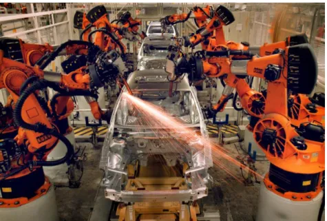
Traditional industrial robot arms feature high payload, high speed, high precision, and high stiffness. A typical example of FANUC robot arm is shown in Fig. 1.1. They are usually large in size for a large workspace and actuated by hydraulic pump for high payload and stiffness. Most of them are 6 degree of freedoms or less depending on the target application. Those robots are targeting on tasks that require much strength high precision and tasks they are boring and repetitive or dangerous such as material handling, welding, automotive manufacturing, etc. Due to their strength, the robot arm must be fenced when they are working and no humans are allowed to enter the workspace. This excludes the possibility of human robot co-existence and human robot collaboration. Although these robots hardly cooperate with humans directly, the programming is often based on teaching by touching technique. With more and more application combined with vision system in small size of robot manipulators, there are some research topics to build up vision-based system in the robot assembly lines [1].
The function in the big robot is no longer restricted in the industrial application.
doi:10.6342/NTU201703382
1.1.2 Lightweight payload robot arms
On the other hand, some researchers and companies tried to lift robot to a higher level by taking the human-robot interaction (HRI) or collaboration (HRC) into consideration. Under the concept of HRI and HRC, the robot arm should be relatively smaller than traditional industrial robot arms. That is to say, some design concepts will follow the request to develop the skill under the circumstances of human-robot coexistence. For example: (a) ABB IRB 1200 is one of lightweight robot arm. Its sleek, smooth surfaces and enclosed design feature all wiring and air routed through the inside of the robot, from very close to the wrist flange all the way to the foot. This further enhances its compactness, and makes the new robot easy to maintain and clean, with no risk of dirt or dust collecting on the cables. (b) Barrett Technology WAM arm is controlled by several steel elastic strings and it is relatively safer than conventional motor driven robot. All the robots mentioned above are listed in Fig. 1.2.
Fig. 1.1 FANUC R1000 series robots
One of the most important requirements for collaborative robot is safety. We don’t want the robot hurt the human that cooperate with her. As a result, they are all capable of sensitive collision detection. The PRob 1R collaborative robot, in Fig. 1.3, was developed to make customers’ lives easier. In fact, when most people think about robotics, they are usually afraid of programming complex routines with a non-intuitive platform. With the help of lightweight design, a modular end effector with soft material makes it safe for humans. There is a switch made through a patented-protected interface that allows a mechanical and electrical connect-disconnect operation to take place. The fingertips of the robot gripper can be adapted for specific application and are easy to switch once the robot is in operation. Another important feature for human robot collaboration is that the robot should be able to interact with human by some gestures.
For example, a famous file shows man play table tennis with KUKA KR Aglius arm [2].
The arm hitting the ball is shown in Fig. 1.4. Due to its high levels of precision at fast speeds, the world No 1 company shows astonishing game to the society that this arm with incredible agility will show reaction after every human gesture. This kind of application verifies that the high precision in the lightweight robot arm can finish the
(a) (b) Fig. 1.2 Lightweight payload robot arms
doi:10.6342/NTU201703382
1.2 Industrial Applications
For industrial robotic applications utilizing a robot arm, the most fundamental functionality required is that the arm should be able to move from the current pose to the target pose so that it picks the machined objects to place on the platform.
Looking back on the industrial production line, factory automation equipped with Fig. 1.3 The PRob 1R collaborative robot
Fig. 1.4 The KUKA KR Aglius is playing table tennis
various industrial mechanisms has already become a mainstream. In recent years, more and more applications have been combined with mechanical manufacture and assembly under the same production line. The automatic part usually refers to robot manipulator operation with intelligent skills. Actually, the intelligent machine preserves advantages to be strong and feasible. For example, the tasks in the production line often contain solid and simple actions. If humans have unlimited time and energy, the work will remain the same. However, humans have to rest periodically to stay efficient. However, robots can retain its performance at a certain level for much longer. Main tasks for machines on assembly lines include processing, assembling, packaging and distributing products. Furthermore, robots or machines enabled to grasp huge workpieces have not yet been invented. Based on diverse applications, operations are designed to solve problems in the production line.
1.2.1 Object fetching
To enhance the productivity in the industrial production line, robots will replace human in the labor intensive works which usually are repeated action. The advantages are to decrease the cost and to make sure the quality of products during the process. It seems that the robot manipulator is indispensable to help humans complete the challenges in the production line. Raising a new method is a trend to establish the capability of robot. The most common work is about object fetching, which is also called pick and place task.
The technique for grasping objects such as industrial products should be developed and teach robot manipulators on the assembly lines. First, machine tools manufacture various industrial products respectively. When those things are produced, the way to put on the conveyor is to grab them with proper command to robot arms. Actually, element
doi:10.6342/NTU201703382 method to pick component from one place to the target position. This can easily be done by repeating mechanical commands. To accomplish more complicated tasks, element information is essential for robots. Sensors play an important role in the scheme of targets on the assembly [5]. Sensory data from vision sensors usually contain the position and orientation of objects on the conveyor. [6] and [7] provide a technique to tell robot where and when to grab elements under designation.
Fig. 1.5 Arm fetch an object
Fig. 1.6 Robot assembly
1.2.2 Assembly
Assembly operations include: fixing, press-fitting, inserting, disassembling, etc.
This category of robotic applications seems to have decreased over the last few years, even while other robotic applications have increased. The reason why the applications are diversified is because of the introduction of different technologies such as force torque sensors and tactile sensors that gives more sensations to the robot.
However, the assembly is still a common application in industrial automation system. Actually, the transmission part would be a fixed conveyor to deliver the element.
At this stage, the task for robot manipulators is simple to move from one place to pick and to target point to place periodically. Besides, without any device to check the position and orientation, there are some challenges happening during the task.
1.3 Challenges
There is a significant bottleneck in the development of industrial automation. The challenge is robot vision system. Due to the recognition performance in the factory, the robot has difficulty finding and picking the elements on the conveyor precisely.
When the target starts to change its movement on the production line, the challenge turns out to be more complicated without any feedback control system. Undoubtedly, a visual system helps to track the moving target and transmits new data to the robot arm.
As a result, a new grasping technique under visual control system is definitely required.
1.3.1 Object recognition
An object recognition system finds objects in the real world from an image of the world, using object models. This task is surprisingly difficult if we want to implement better effort in the robot. Humans perform object recognition effortlessly and
doi:10.6342/NTU201703382 region and recognizing the target. But by means of object recognition system, the manipulator has an eye to understand the surrounding where a lot of unknown factor exists. Therefore, this system plays an important role in pick and place task.
1.3.2 Robot vision system
Visual camera is a common piece of equipment in the robotic picking tasks. The robot vision system is considered as assistant to finish work. The 2D data is derived from webcam and transformed into poses for robot arms [8]. Some image processing algorithms have high impact on object recognition, increasing the success rate of grabbing [9]. Moreover, Kinect sensors are famous for its depth information, which assist robot end-effectors in grasping. [10] and [11] show the advantages of depth data to enhance entire process of conveyor tracking. Compared with a laser scanner, a tilting laser range finder, the 3D geometry sensors in [12] would be more straightforward to describe element situation from elements to robot arms. As a result, cameras are one of the key points under pick and place tasks.
However, there are a lot of unexpected conditions to consider in the assembly lines and these problems need to be solved. In this condition, the unexpected part is moving conveyor. Sensor integration brings about a comprehensive conception on robot grasping. Equipped more sensors can not only deal with complex environment but also decreases the error rate of a task [13]. There are two ways to describe the relationship between arms and cameras. One is camera to hand and the other is eye-in-hand. Camera to hand is common to send background information to control center. Eye-in-hand usually transmits object state to computer to revise the position and orientation of targets immediately if problems happen in the environment. Moreover, the movement of robot manipulators is not always stable. To strengthen the function in perception system, the condition should be recorded so that all motion will remain more fluent next time.
Besides, with the help of communication between robot and PC, the development of robot can be implemented by programming. With additional and various sensors such as vision, force, light, and current, the robot arm can not only fully reach to the target point but also integrate with sensor data in a flexible way. However, in the developer part, it takes tediously long time to integrate different system signal to deal with numerous changes happening to the assembly lines. Probably the work is only for customized design. To match more robots in the market, if the program is not suitable for more device or more sensors, the process for robot manipulator may change a lot to even to rewrite the whole control system. Therefore, visual feedback control is a relative convenient system to cope with the problems suddenly happening with the help of content from vision sensors. A famous technique, intuitive teaching by touching, is often used as visual feedback system to complete robot grasping. A block diagram is shown in Fig. 1.7.
doi:10.6342/NTU201703382
1.4 Thesis Structure
In this thesis, we introduce the idea of tracking strategy to grasping moving objects on the assembly lines. In Chapter 2, we briefly introduce the scenario of experiment in the thesis, including the problems to solve, the functionalities to build and the procedures to implement. There are two kinds of situation in the industrial elements. In Chapter 3, there are three main architectures to illustrate the process implemented in this research. The second one and third one is about tracking method. After pointing out the thesis structure, we start to introduce each method in the following chapters. In Chapter 4, the manipulator will be illustrated in solid part and programming. Because the robot is the center of this technique, the fundamental functionalities will be shown in this chapter. In Chapter 5, we will focus on how the robot knows to grasp the object by recognition system. The main technique, tracking strategy, will be introduced in Chapter 6. The process to complete the pick and place task is written in details. In Chapter 7, the experimental results will be shown and discuss them in comparison with theoretically prediction. Last of all, we conclude whole thesis with future works in Chapter 8.
Chapter 2 Scenario
2.1 Experimental Setup
The main goal in this research topic is to pick up a moving object from the conveyor to the platform. The associated factors to complete the task will be fully illustrated in the following subsections.
2.1.1 Scene
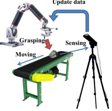
The scene of our experiment is illustrated in Fig. 2.1. Objects to be picked up are transmitted by a conveyor. The object is moving among whole process. The manipulator is a 7-DoFs robot arm which is designed and assembled in our lab. There is a 3 finger gripper in the tip point to grasp objects on the moving conveyor. The visual sensors are able to sense any difference happening in the environment. In this research, the system is sensor-integrated with two vision sensors including Microsoft Kinect and webcam camera.
Fig. 2.1 An industrial task outlining the pickup of moving objects
doi:10.6342/NTU201703382
2.1.2
Faced problemsFor a proper robot assembly, some fundamental functions should be constructed including manipulator control, object recognition and fetching and dynamic factor. The whole process to list will be introduced in Chapter 4. When the manipulator functions, there are some problems robot must handle. In factories, most of the problems are the instant position and orientation of object. In object recognition system, the lighting condition may also affect the color or intensity feature of the object. When this basic factor hasn’t been solved, the robot is unable to hold an object, let alone grasp moving one.
2.2 Procedures
The whole procedures can be separated into two parts: static and dynamic.
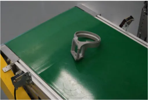
In static part, the industrial elements are put on the conveyor and being transmitted to a certain region where the light sensor is mounted. The light sensor in Fig. 2.2 will be trigger and stop the conveyor so that the part will stop and wait for subsequent
Fig. 2.2 The light sensor of the conveyor
operations. At the meantime, the light sensor will send a signal to the computer and start the object recognition algorithm to identify the type as well as the pose of the element.
After the success of the object recognition, the manipulator will go along a pre-taught trajectory to the ready pose and then pick up the object using a pre-taught grasp. The manipulator will then start the operations for the object such as assembling, polishing, painting, etc. After the current task accomplished, the manipulator will send a signal to the conveyor and transmit the next part for the next operation. The cycle then repeats itself.
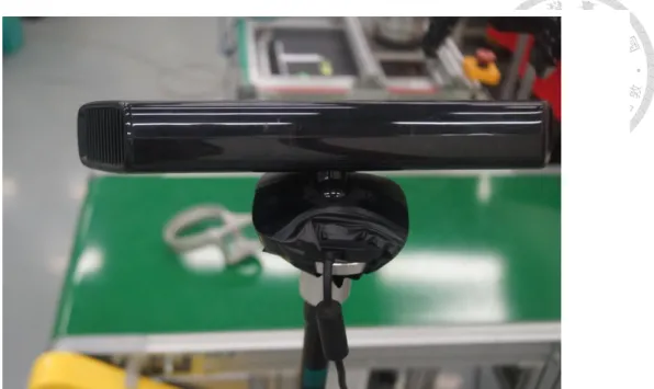
When the conveyor starts to move, there are several dynamic factors on the conveyor. The vision sensors are used as monitors to sense any variation in the experiment. In this thesis, two ways to describe the relationship between arms and cameras will be illustrated. The first way is eye to hand, shown in Fig. 2.3. Robot eye stands at a relative position to the robot hand. This means that the camera is set near by the robot manipulator and its distance remains solid. When the conveyor start to transmit the objects, the camera will check the instant position and recognize the object at the same time. After receiving new data from vision, the end-effector will run to the target to pick up the object. The other one is eye in hand, shown in Fig. 2.4. Literally, on the tooltip of manipulator, there is an eye on it. This eye helps to track the object immediately. However, the view may include partial body of object. To calculate the area of object in the camera frame, it is important to segment the 640 x 480 view. Only a small region is interested in the procedure. The robot manipulator will track the object three times and grasp it before it falls down to the ground. Therefore, the dynamic factors can be solved by two tracking skill. The vision sensor used in eye to hand is Microsoft Kinect, and the other one in eye in hand is webcam camera.
doi:10.6342/NTU201703382
2.3 Preconditions
In industrial scenarios, the environment is rather controllable compared with household scenarios. As a result, with some assumptions properly made, we can greatly increase the efficiency of the system. Furthermore, we can setup the environment to meet the precondition of some algorithms, in our case the object recognition algorithms,
Fig. 2.3 Eye to hand system (Microsoft Kinect sensor)
Fig. 2.4 Eye in hand system (webcam camera)
so that those powerful algorithms can be adapted to meet our requirement of the system such as high reliability, ow time consumption, and so on.
2.3.1
Structured environmentIn industrial scenario, the environment is controllable. We can build fences around the robot which prohibits humans from going inside. The environment can be fixed once the system has been deployed. As a result, if the robot can work in a well -controlled and structured environment, which should not be a big problem setting up such environment in industrial scenarios, the robot will not have to take online motion planning and obstacle avoidance into account. The robot can simply follow a pre-programmed and time-optimal trajectory to go to the target pose and perform its tasks swiftly and safely.
2.3.2
Objects descriptionWe assume that objects or components that may occur in the scenario are all rigid bodies. They would not deform or break on account of external forces. Following this assumption, model-based object recognition algorithms can be applied. The states of the object can be described by its type and the 6-DoFs rigid transform in the 3D Cartesian space. The internal states such as the deformation can be neglected under the rigid body assumption. Furthermore, the feasible grasp for picking up the object stably can be described easily. Other factors such as the exerted force of the gripper, the damage of the object and the deformation of the object are not taken into consideration. Only the grasp point is required for describing the proper grasp, which is simply the 6-DoFs pose of the end-effector in the object’s coordinate.
doi:10.6342/NTU201703382
Chapter 3 System Architecture
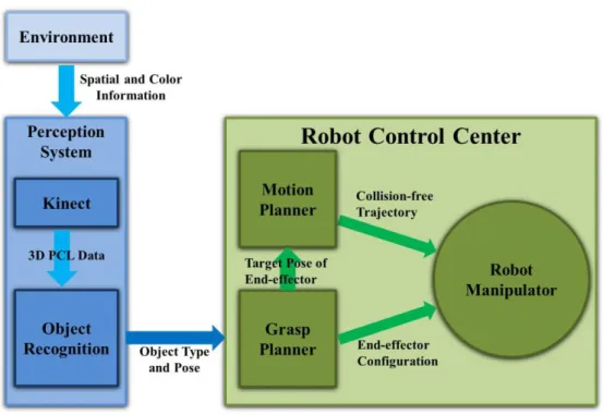
3.1 Generalized Robot Fetching Architecture
The generalized system architecture and the required su0modules for a robot fetching system are shown in Fig. 3.1. The environment is sensed by 3D sensors that describe the robot’s workspace with the color, the geometry, or both. The sensed environment information is then transmitted to the object recognition module which recognizes the target objects in the workspace. The output result is the pose and the type of the target objects in the workspace. Since the type of the objects in the scene is known, their models can be retrieved from the database for grasp planning. The resulted grasp contains the pose of the end-effector and the configuration of the end-effector. The former one should go through a motion planner which generates a collision=free trajectory for robot arm execution, while the latter one will be sent to the end-effector, which could be a gripper, for actually holding the object.
Fig. 3.1 Generalized robot fetching architecture
This architecture, though dealing with general situation, suffers from high computational complexity in the online grasp planning and motion planning. In an industrial scenario, the efficiency, which is closely related to the cost and the yield rate, is one of the major concerns. We not only require the robot to correctly complete the tasks but also need the tasks to be done quickly. As a result, in this research, we based on the assumptions made in the subsection 2.3 and substitute the online grasp planner and the motion planner modules with the operation database and trajectory interpolator respectively.
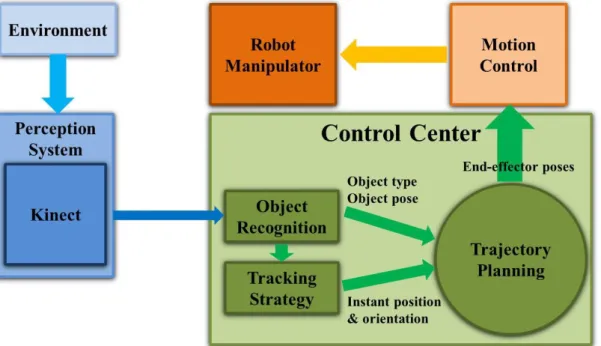
3.2 Specialized Robot Fetching Architecture
The main objective in this research is to build up a sensor-integrated system that can grab moving objects with pose modification in the assembly lines. The system architecture is shown in Fig. 3.2.
Why it is called specialized? This means the model functions in specific situation.
Fig. 3.2 Flow chart of specialized robot fetching system architecture.
doi:10.6342/NTU201703382 specialized method is for tracking objects. Poses of robot end-effector are decided by 3D sensor data. The poses will be separated into two conditions. First, we have to collect static poses for each element from visual recognized results. This can be determined by Kinect sensor in the generalized robot fetching architecture. According to the assumption explained in subsection 2.3.1, the workspace will not change when the robot is performing its tasks. As a result, all we have to do is define some trajectory via-points, along which the robot will not hit itself or collide with the fixed environment.
Since the environment is fixed, this trajectory always applies and can be stored in a database for later use. Since the environment is fixed, we can guarantee that this trajectory will never collide with the environment afterward. Therefore, the object type and pose will be sent to trajectory planning to calculate the static grasping pose and command the robot.
The task would become tough after objects are moving on the conveyor. In the same way, the environment is sensed by 3D sensors that describe the condition happening on the conveyor. There are two way to receive information from sensors: eye to hand and eye in hand. In this research, the sensor used in eye to hand is Microsoft Kinect sensor and the other one is webcam camera on the robot tooltip. Actually the moving pose derived from visual is a certain point in the camera coordinate. This will be transferred to the point under Cartesian Space coordinate. After tracking block finishing the computation, the instant state of the object, including its pose and orientation, will be transmitted to the trajectory planning. The robot manipulator then reaches to designated position to get ready to catch the object. In general, information from perception system will update the state of objects to the control center after the end-effector poses have been decided. Therefore, robot arm is able to grasp moving objects successfully.
The method in eye in hand is under the same architecture. The difference is that the end-effector will follow the position in the webcam view to change its position. This behavior seems to be what tracking it is.
The detail of our system is described in the Chapter 6.
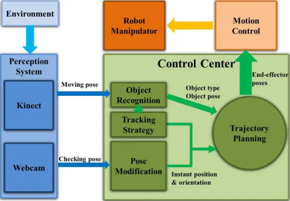
3.3 Modified Robot Fetching Architecture
Actually, the main goal in this thesis is to grasp an object before it falls down to the ground. It seems that holding the target is success action in the result. However, to check the condition precisely, the grasping pose has a little difference from the desired command. If there is an offset or deviation angle, the task hasn’t been completed yet. To check out whether the task is successful or not, the webcam is used to record image while the gripper is holding the object. The conceptual structure is shown in Fig. 3.3. To find out any variation of grasping pose, webcam will first store lots of correct pose
Fig. 3.3 System structure for modified robot fetching.
doi:10.6342/NTU201703382 picture in a database. After gathering the poses as a standard level, the mission starts to grasp moving target. In this step, the grasping pose will be compared with desired command. The error model will be told in subsection 6.3.3 in details
Chapter 4 Manipulator
In this thesis, all algorithms are well-functioned only if the robot manipulator performs good behavior. How robot move and grasp should be designed at the beginning. Therefore, the main body will be fully introduced in its hardware structure and software functionalities.
4.1 Mechanism
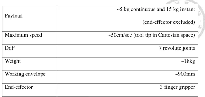
The 7-DoFs of robot manipulator is shown in Fig. 4.1 in our lab [14]. The hardware has been built up by an alumnus of our lab three years ago. In this part, we will put emphasize on the detail pieces of robot, kinematics, control architecture and the software functionalities. The readers are encouraged to read the in-depth discussion on the hardware in the reference thesis [14]. The specifications of the robot manipulator are listed in Table 4-1. The payload is 5 kg without end-effector. However, the weight of 3 finger gripper is 2.3 kg. Thus, the actual payload is at most 2.7 kg, which need to be
Fig. 4.1 iCeiRA arm one in iCeiRA lab
doi:10.6342/NTU201703382
4.1.1 D-H parameters
To begin with, the model of robot manipulator to describe its hardware in a standard way is illustrated by the D-H parameter method. Jacques Denavit and Richard Hartenberg introduced this convention in 1955 in order to standardize the coordinate frames for spatial linkages [15]. To be precise, 4 parameters are needed to describe the relationship between adjacent links and joints. They are 𝜃, 𝑑, 𝑎 and 𝛼. In Fig. 4.2, the procedure for attaching coordinate on the link and identifying these 4 parameters are described as follows:
Link frame attachment procedure:
1. Identify the joint axes and imagine (or draw) infinite lines along them. For step 2 through 5 below, consider two of these neighboring lines (at axes 𝑖 and 𝑖 + 1).
2. Identify the common perpendicular between them, or point of intersection. At the point of intersection, or at the point where the common perpendicular meets the 𝑖𝑡ℎ axis, assign the link-frame origin.
3. Assign the 𝑧̂𝑖−1 axis pointing along the 𝑖𝑡ℎ joint axis.
Payload
~5 kg continuous and 15 kg instant (end-effector excluded)
Maximum speed ~50cm/sec (tool tip in Cartesian space)
DoF 7 revolute joints
Weight ~18kg
Working envelope ~900mm
End-effector 3 finger gripper
Table 4-1 spec of the iCeiRA arm one
4. Assign the 𝑥̂𝑖−1 axis pointing along the common perpendicular, or, if the axes intersect, assign 𝑥̂𝑖−1 to be normal to the plane containing the two axes.
5. Assign the 𝑦̂𝑖−1 axis to complete a right-hand coordinate system.
6. Assign frame {0} anywhere in the supporting base as long as the 𝑧̂0 axis lies along the axis of motion of the first joint. The last coordinate (frame {0}) can be place anywhere in the end-effector as long as the 𝑥̂𝑛 axis is normal to the 𝑧̂𝑛−1 axis.
7. Try to assign the link frame so as to cause as many linkage parameters as possible to become zero.
D-H parameters in terms of the link frames:
𝑑𝑖:the distance from 𝑥̂𝑖−1 to 𝑥̂𝑖 measured along 𝑧̂𝑖−1
𝜃𝑖:the angle from 𝑥̂𝑖−1 to 𝑥̂𝑖 measured along 𝑧̂𝑖−1 Fig. 4.2 The definition of four parameters
doi:10.6342/NTU201703382
𝛼𝑖:the angle from 𝑧̂𝑖−1 to 𝑧̂𝑖 measured along 𝑥̂𝑖
After following the rule of D-H parameters, it is common to assign the link frames to identify the model of iCeiRA arm one. Each frame, coordinate definition and the D-H parameters are shown in Fig. 4.3. When all frames are defined in a proper solution, there is a D-H table to figure out the relationship between each revolute joint and the joint limit for the movement. The statistic is listed in Table 4-2.
After we receive the table, the DH transformation matrix from one coordinate from to the next is well implemented. Using a series of D-H Matrix multiplications, the final result is a transformation matrix from desired frame to initial one.
𝑀𝐷𝐻 = 𝑅𝑧,𝜃𝑖𝑇𝑧,𝑑𝑖𝑇𝑥,𝑎𝑖𝑅𝑥,𝛼𝑖
= [
𝑐𝜃𝑖 −𝑐𝛼𝑖𝑠𝜃𝑖
𝑠𝜃𝑖 𝑐𝛼𝑖𝑐𝜃𝑖 𝑠𝛼𝑖𝑠𝜃𝑖 𝑎𝑖𝑐𝜃𝑖
−𝑠𝛼𝑖𝑐𝜃𝑖 𝑎𝑖𝑠𝜃𝑖 0 𝑠𝛼𝑖
0 0
𝑐𝛼𝑖 𝑑𝑖
0 1
]
(4-1) Fig. 4.3 Link frames assignment of iCeiRA arm one
4.1.2 Transmission and actuator
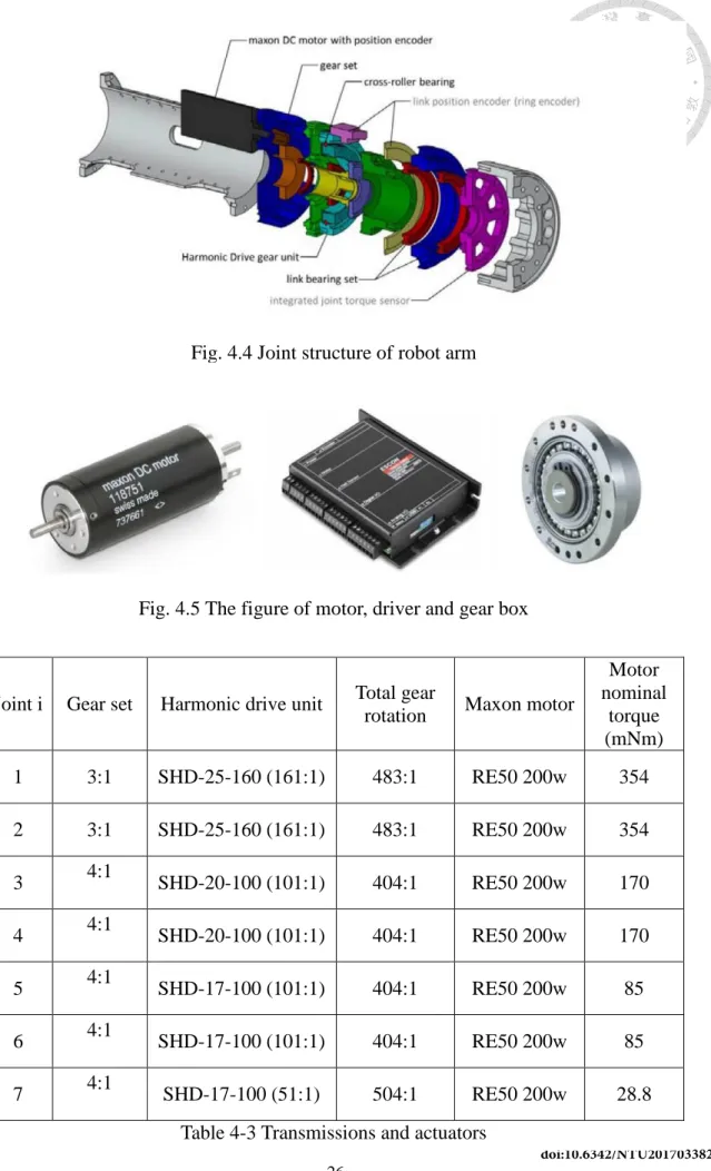
The hardware structure of the one of the joints is shown in Fig. 4.4. To build up a whole manipulator, the key component including motors, drivers and gear box is indispensable. Those devices are shown in Fig. 4.5. The Maxon DC motor is chosen due to its excellence in the smaller size and high torque output. The dedicated motor driver is capable of current control, which indicates that we can directly control the torque of each motor. The gear box has two parts: one is gear set and another one is harmonic driver. The output torque from the motor is transmitted through a gear set, harmonic drive and then the joint. The advantages of harmonic drive are that they have compact size, high reduction ratio, and no backlash so that the size and weight can be reduced significantly. The detailed specifications on the reduction ratio and the motor are listed in Table 4-3. By means of those devices, the iCeiRA arm one now start to build up its
Joint i 𝜃𝑖(rad) 𝑑𝑖 𝑎𝑖 𝛼𝑖 𝜃𝑢 𝜃𝑙
1 𝜃1 + 0 𝑑𝑏𝑠 −90° 180° −180°
2 𝜃2+ 0 90° 120° −90°
3 𝜃3+ 0 𝑑𝑠𝑒 𝛼 −90° 180° −180°
4 𝜃4 + 0 −𝛼 90° 180° −45°
5 𝜃5+ 0 𝑑𝑠𝑤 −90° 180° −180°
6 𝜃6+ 0 90° 100° −100°
7 𝜃7+ 0 𝑑𝑤𝑡 0° 360° −360°
𝜃𝑢: joint angle upper bound 𝜃𝑙: joint angle lower bound Table 4-2 D-H table of iCeiRA arm one
doi:10.6342/NTU201703382 Fig. 4.4 Joint structure of robot arm
Fig. 4.5 The figure of motor, driver and gear box
Joint i Gear set Harmonic drive unit Total gear
rotation Maxon motor
Motor nominal
torque (mNm)
1 3:1 SHD-25-160 (161:1) 483:1 RE50 200w 354
2 3:1 SHD-25-160 (161:1) 483:1 RE50 200w 354
3 4:1
SHD-20-100 (101:1) 404:1 RE50 200w 170
4 4:1
SHD-20-100 (101:1) 404:1 RE50 200w 170
5 4:1
SHD-17-100 (101:1) 404:1 RE50 200w 85
6 4:1
SHD-17-100 (101:1) 404:1 RE50 200w 85
7 4:1
SHD-17-100 (51:1) 504:1 RE50 200w 28.8 Table 4-3 Transmissions and actuators
4.1.3 Gripper
The iCeiRA arm one is equipped with a Robotiq 3-finger gripper [16], which is shown in Fig. 4.6. This is the end-effector for object fetching system in industrial assembling application. This type of gripper owns two type of grasping: encompassing grip and fingertip grip. In our research, the fingertip grip is selected for grasping.
Fig. 4.6 Robotiq 3-finger gripper
doi:10.6342/NTU201703382 The specification of the Robotiq 3-finger gripper is listed in Table 4-4. The dimension and the workspace of the gripper are shown in Fig. 4.8. The gripper is able to open no more than 155mm width. There are rubbers stick on the inner contact surface of each finger to increase the friction between the finger and the grasped objects. The friction coefficient of the rubber is 0.4.
We choose this 3 finger gripper because of its adaptiveness. The special linkage design of the mechanism makes it compliant to the shape of its holding object.
Furthermore, the motor will halt once the resistant force is beyond a given value, which Fig. 4.8 Dimension and workspace of gripper
DoF 4
Weight 2.3 kg
Payload for encompassing grip (Fig. 4.7 left):10 kg 10 kg Payload for fingertip grip (Fig. 4.7 right):2.5 kg 2.5 kg
Force 15~60N
Object diameter 20~155mm
Table 4-4 spec of gripper
is good for grasping objects of unknown shape without damaging it. Once the motor is halted due to the external resistant force, it will not continuously exert force, which may result in over-heating of the motor. On the other hand, the current position will still be maintained by the linkage mechanism.
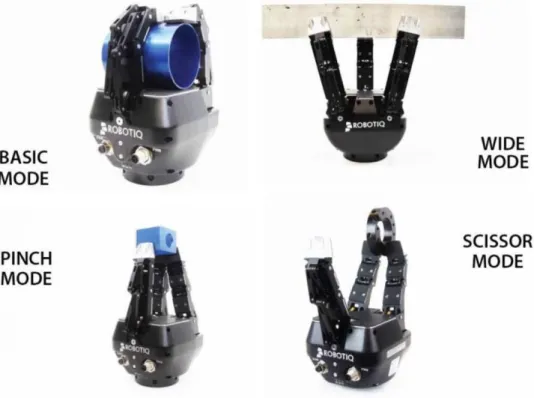
There are 4 operating modes: basic, pinch, wide and scissor mode as depicted in Fig. 4.9. The basic mode is commonly used mode and is suitable for most of the cases.
It is especially, suitable for cylindrical or stick sharp objects. The wide mode is designed for holding large or round object. The pinch mode and scissor mode are used for picking up small objects precisely. The scissor mode is even more precise than the pinch mode at the expense of payload and adaptiveness. These 4 operation modes are sufficient to cover most of the use cases. If the user requires a more dexterous manipulation, it can also control each finger individually. In this thesis, the basic mode and pinch mode are the main operation to finish grasping action.
Fig. 4.9 Four operation modes of the gripper
doi:10.6342/NTU201703382
4.2 Control Architecture
The control architecture of iCeiRA arm is shown in Fig. 4.10. A PC running in RTOS is the control center of the whole system. It communicates with the hardware components such as the motor driver and the motor encoder through a DAQ card installed on the PCI bus. The RTOS is required since we would like to do the motor position control on the PC running at 1 kHz.
The DAQ card is installed in the PCI bus of the PC, which endows the PC with the capability of sending an analog voltage signal to control the motor driver and reading the encoder count from the motor. On our platform, one PISO-DA8U [17] for 8 channel analog output, and two PISO-Encoder600 [18], each for 6 channel encoder count, are chosen.
When received the analog voltage signal from the DAQ card, the motor driver will output a corresponding current to drive the motor. This implies that the current control loop is done internally by the motor driver. For example, when the driver receives 10V signal, it will output the positive maximum current, which can be set using a variable
Fig. 4.10 Control architecture in robot control system
resistor on the driver. The unit of the drive current is in Ampere. On the other hand, when the motor receives -10V signal, it will output the negative maximum current; and when it receives 0V, it will output zero current. In our case, Maxon ESCON 70/10 is chosen, which support maximum output power of 700W and maximum output current of 10A.
The motor is driven by the current from the motor drive and output a torque to actuate the robot arm. The output torque equals to the product of the input current and the torque constant of the motor. The rotating angle will be count by the encoder equipped on the motor and then feedback to the PC through the DAD card. This closes the loop so that the accurate position or velocity control can be done on the PC.
4.3 Software Architecture
Fig. 4.11 Software architecture
doi:10.6342/NTU201703382 architecture is divided into three layers: application layer, basic utilities and hardware layer. In this section, the motivation why to build this architecture will be described.
The functionalities in each layer will also be explained.
4.3.1 Motivation
The motivation for proposing this software architecture and rebuild the whole software for the robot is that we require a clearly defined and modularized architecture for future development and maintenance. The first version of the robot’s software was built by an alumnus of our lab 3 years ago, who is also the designer of the iCeiRA arm one mechanism. We acknowledge and appreciate his effort in building the mechanism and also the basic software utilities of the robot arm such as motor control, trajectory planning, intuitively teaching by touching, and so on. However, the software part hasn’t been developed yet. To made the maintenance of programming, there layers is created to illustrated the functionalities of robot manipulators and extend the capabilities of iCeiRA arm one.
4.3.2 Hardware Structure
The hardware layer is the abstraction of the hardware components. The abstraction of the robot such as the D-H modes, controller parameters, dynamic parameters, etc, is encapsulated in the Robot Parameter module. The abstraction of the PC are divided into two modules, one is the RTOS, which provides a precise real time timer, and the other is the communication interface, which can be DAQ card, RS 232, CAN-BUS, EtherCAT [23 24], etc. this layer strongly depends on the hardware. For different robots, the functionalities of this layer can support might change drastically. As a result, we would not try to standardize this layer and unify the interface of each module. Instead, the programmer should try to identify the hardware dependent parts and classify them in
this layer so that other modules would depend less on the platform which makes porting this program onto other platform easier.
4.3.3 Basic Utility
This layer provides the basic utilities for building up robotic applications. For example, the robot kinematics and dynamics are the most fundamental utilities that almost all the robotic applications will require. The logger module is for recording various states of the robot arm such as joint position, joint velocity, joint torque, tool tip Cartesian space position, Jacobian, etc. The logger module will dump the recoded states into the hard disk for latter analysis. Some other modules such as the Joints, Sensors, and Grippers also belong to this layer. The programmer will not have to handle the low-level communication interface signal to control the motor or retrieve the sensor data.
On the contrary, they can use the abstract Joints and Sensors modules to complete their task more conveniently. This layer is partially dependent on the platform mostly because of the Joints, Sensors, and Gripper module. These modules usually have strong dependency on the communication interface. For example, the joints might be connected in series and communicate with EtherCAT and sometimes the sensor signal is retrieved from a DAQ card installed on the PC’s PCI bus.
4.3.4 Application Layer
The purpose of the two aforementioned layers is to provide most of the necessary utilities and a proper abstraction for high-level robotic applications. With these two layers, developers can build their own application in the top layer – the application layer.
This layer is independent of the hardware. It is more like a collection of the fancy functionalities. Most of the programmers can develop their own algorithms in this layer and don’t have to get their hands dirty. Handy, basic and powerful utilities are provided
doi:10.6342/NTU201703382 in the second layer such as the kinematics, dynamics, joint control, and so on. Other programmers can harvest the hard work which have been done in the hardware layer and the basic utility layer, and do their research and develop new algorithms in this layer.
We further divide this layer into two different groups – the active skill and the passive skill. The former one refers to services that operate only when they are called, while the latter one will operate periodically behind the scenes. One of the examples for the active skill is the Cartesian Space Control, which is the control of the end-effector from its current pose to a give target pose. The robot will have to run the service only when it gets the order to go to some target pose. On the other hand, the Safety, which should detect the collision between the robot and the environment, belongs to the passive skill since the robot will have to check the whether the collision occur periodically.
4.3.5 Timer
In this architecture, three threads are created to perform different tasks. The active skills and the devices such as the Joints, Sensors, and Grippers, are updated in the first thread. This thread is a real time thread which will update at 1 kHz. Among all the thread, the first thread is most time-critical. It involves the update of the motor feedback command, sensor data, and current performed task. The second thread updates the passive skills and the robot states. This is also a real time thread in order to retrieve the latest robot state and the immediate reaction to safety issues and internal errors. The third thread is for the logger. This thread need not be a real time thread since it performs lots of data read/write on the hard disk. The task is neither time nor safety critical.
Therefore, a relatively resource consuming real time thread is not required for this operation.
4.4 Manipulator Functionalities
After describing the software architecture and hardware device, it is time to develop the basic functionalities of robot manipulators. In this section, the two techniques are essential for iCeiRA arm one to implement assembling task for industrial application.
4.4.1 Intuitive teaching by touching
It is the user’s responsibility to tell the manipulator where to go. Usually, we concern only about the pose of the end-effector in Cartesian space since it is the end-effector that interacts with the environment. In industrial application, the operator will record a series of end-effector poses and the manipulator simply replays these poses when performing its tasks. Therefore, it is the operator’s responsibility to record the series of poses precisely so that the manipulator can finish its task successfully.
Traditionally, the operator will command the robot to go to a target pose using the teaching pendant or direct key in a pose. The operator will fine tune the pose until the robot reach the desired target pose and then record the current pose. This process is actually tedious, time-consuming and counter-intuitive. Therefore, here we introduce the teaching by touching [19][20] so that the operator can guide the robot direct and teach the robot intuitively and quickly. The teaching by touching enables the operator to move and guide the manipulator directly by hand. Therefore, the operator can guide the robot to the desired pose and fine tune the pose intuitively.
Generally, it is impossible and not allowed to guide the robot. That is to say, it is difficult to move the robot to another pose by hand. The major reason is that the motor will try to maintain the current pose so that it will exert torque to resist external forces.
Some minor reasons include the high reduction gear, friction in the transmission,
doi:10.6342/NTU201703382 mechanism weight, etc. to solve the major problem, the manipulator will have to sense the direction of the external force and comply with the external force instead of resisting it. In our case, we did not rely on an additional sensor such as the force torque sensor.
Alternatively, we compute the direction of the external force by the following formula:
𝛿𝑥 = 𝐽(𝑞)𝛿𝑞 (4-2)
, where 𝛿𝑥 is the slight variation of the tooltip’s pose in Cartesian space, which can be defined as
𝛿𝑥 = [
𝛿𝑥 𝛿𝑦 𝛿𝛼𝛿𝑧 𝛿𝛽 𝛿𝛾]
(4-3)
, where 𝛿𝛼, 𝛿𝛽, 𝛿𝛾 are the rotation angle relative to reference coordinate of x, y, z axis.
The 𝛿𝑞 is the slight variation of the hoint angle measured from the encoder error, and the 𝐽(𝑞) is the Jacobian matrix calculated from current joint angle 𝑞. As a result, 𝛿𝑥 can be regarded as the direction of the external force. As for the minor problems, gravity compensation and the friction compensation must be included to resist the mechanical weight and the friction respectively. The gravity compensation is calculated from the mass center to maintain static equilibrium. The friction compensation is a constant to resist the static friction of each joint.
Besides the basic intuitive teaching by touching functionality, we further decouple the guided motion into translation and rotation. In the translation mode, the orientation of the tooltip is fixed while the position can be guided freely by the operator. On the other hand, in the rotation mode, the position of the tooltip is fixed while the orientation can be guided freely.
In the translation mode, once the encoder error is above a threshold, the robot will
move along the direction of the external force. However, if we simply let the robot moves along that direction, the orientation will change inevitably. As a result, we solve the inverse kinematics for the new pose while setting the orientation to the current one.
This equivalently makes the manipulator moves along the guided pose with the orientation fixed. The same idea applies to the orientation mode in which the position of the tooltip is fixed while the orientation can be guided by the operator freely.
4.4.2 Online trajectory generation
The generation of command variables for industrial manipulator has two functions:
specification of the geometric path (path planning) and specification of the progression of position, velocity, acceleration, and jerk in dependence of time (trajectory planning).
The literature provides many of approaches and algorithms in both fields.
The goal of trajectory planning is generating smooth motion in multidimensional space refer to a set of planned waypoints or path points by using some given parameter, i.e. the time interval of a motion, boundary conditions of motions, the maximum velocity limit, acceleration limit or even jerk limit. The smooth motion is a function of time that is continuous and has a continuous first derivative. Sometimes a continuous second derivative is also desirable. Jerky motion tends to cause vibration in the manipulator and cause increased wear on the mechanism. There are many methods about trajectory generation have been used in many systems, such as the cubic spline line, B-spline [21], tension spline [22], the linear function with parabolic blends and NURBS [23]. The above methods generate trajectory that consist by numbers of segments which are functions of time and smooth connect each segments by matching the boundary conditions. Then the trajectory can be generated at run time, that is, the trajectory points can be computed at each servo loop or sampling time in control system.
doi:10.6342/NTU201703382 predictable so that we can compute it offline. However, in the case when the waypoints are unknown and unpredictable, the frequently change of the next waypoint will let us need to re-calculate a new computing equation of next trajectory segment to remain smooth motion in real-time. There is other type of trajectory generator has essentially online calculation. An online trajectory generator is a real-time trajectory planning algorithm for computing the interpolation of synchronized and time-optimal smooth motion in multi-DoFs with arbitrary input values. The next trajectory set point is computed according to current state of motion every control cycle, typically every millisecond. This enables system to react instantaneously to unforeseen and un- predictable event, usually sensor trigged event, at any time instant and in any state of motion.
The interface of an OTG has basic form shown in Fig. 4.12 and the OTG have the following specifications:
The input values for the trajectory generator are completely arbitrary. Expect the motion state 𝑝⃗𝑖−1, 𝑣⃗𝑖−1, 𝑎⃗𝑖−1 of the last control cycle, all values may change between the control cycles. This means that This means that the target position 𝑝⃗𝑖𝑡𝑟𝑔𝑡, (the target velocity 𝑣⃗𝑖𝑡𝑟𝑔𝑡), the max. velocity 𝑣⃗𝑖𝑚𝑎𝑥, the max. acceleration 𝑎⃗𝑖𝑚𝑎𝑥, and the max. jerk 𝑗⃗𝑖𝑚𝑎𝑥 are not constant nor continuous.
The trajectory is calculated on-line (in real time during every control cycle), because the input values may change unpredictably. Only the next sample point, the 𝑝⃗𝑖, 𝑣⃗𝑖, and 𝑎⃗𝑖 is calculated within one control cycle 𝑖.
Synchronization: the OTG consider an N-dimensional space, where N is the number of DoFs. The input and output are N×1 vectors in the space. For the manipulator, it is in joint space or Cartesian space. Synchronization is important requirement, that is, all N DoFs have to reach their target position simultaneously
at zero velocity and zero acceleration. Furthermore, for the straight line motion of manipulator’s end-effector, the phase-synchronization is required so that all N DoFs will not only reach their target at same time but also change the state of motion simultaneously. For example, all N DoFs change their motion state from acceleration to constant velocity at same time.
The generated trajectory for the DoF with the largest execution time is time- optimal. The constraints for other DoFs are adapted for synchronization.
An OTG do not consider path planning. The desired target position 𝑝⃗𝑖𝑡𝑟𝑔𝑡 is user-given.
In recent times works on OTG have been published, e.g. [24][25]. A new control Fig. 4.12 The input and output of an OTG algorithm