TRANSIENT THERMAL ENERGY STORAGE IN A PARTITIONED ENCLOSURE PACKED WITH MEPCM
Yong-Hao SIAO1, Wei-Mon YAN2*, Chi-Ming LAI3, and Yu-Fan LIN2
1 Department of Mechanical Engineering, National Cheng-Kung University, Tainan 70101, Taiwan;
2Department of Energy and Refrigerating Air-Conditioning Engineering, National Taipei University of Technology, Taipei 10608, Taiwan;
3Department of Civil Engineering, National Cheng-Kung University, Tainan 70101, Taiwan ABSTRACT
The transient thermal storage characteristics in a partitioned enclosure filled with microencapsulated phase change material (MEPCM) particles were investigated experimentally and numerically in details. The core phase change materials of the MEPCM are n-octadecane with melting temperature about TM= 28oC and 37oC and filled at the upper and lower partitions in an enclosures. The enclosure is partitioned and is differentially heated by the two horizontal isothermal surfaces, while the other vertical surfaces are considered thermally insulated. The studies have been undertaken for different hot and cold wall temperatures imposed across the enclosure. The consequents show that the numerical results are in agreement with the measured data. Predictions show that at the initial transient, the net energy storage in enclosure, Qnet, increases with the time Fo. Finally, the Qnet approaches quickly the steady state for the case with a higher temperature difference of Th-Tc.
1. INTRODUCTION
Latent heat thermal storage (LHTS) in general, and phase change material (PCM) storage in particular, have been examined for over 20 years and are stated in the open literatures. The compressive reviews about the materials, applications and heat transfer characteristics of PCMs are available in Refs. [1-3]. Numerical analysis of melting and freezing of a PCM thermal storage unit with varying wall temperature was presented by Halawa et al. [4]. In their model, the thermal storage unit was assumed to be several layers of thin slabs of a PCM subjected to convective boundary conditions where air flows between the slabs. Lazaro et al. [5]
presented an experimental study on PCM–air real-scale heat exchangers. The results indicated that a heat exchanger using a PCM with lower thermal conductivity and lower total stored energy, but adequately designed, has higher cooling power and can be applied for free-cooling. In spite of various advantages of PCMs, LHTS systems possess a major disadvantage: low melting and freezing rates due to low thermal conductivity of the PCM.
In practice, suitable packing of the bulk PCMs has been a technical issue, in particular, in the aspects of maintaining their shape in and preventing leak of liquid PCM from the containers during the phase change process. To this end, microencapsulated phase change material (MEPCM) technique has been developed with several advantages. Addition of MEPCM in working fluid is considered to be a potential heat transfer enhancement cooling fluid. Goel et al. [6] examined experimentally the thermal cooling performance in ducts with water-based suspensions of MEPCM particles. Measured results indicated that the coolant with phase change material suspensions can reduce the wall temperature rise by up to 50% as compared to a pure coolant. A novel insight for the forced convective heat transfer enhancement of MEPCM slurries flowing through a circular tube with constant heat flux was presented by Hu and Zhang [7]. They pointed out that in circular ducts, the heat transfer for pure fluid is different from one for fluid with MEPCM suspensions. Ho et al. [8] numerically investigated the pipe wall conduction on the heat transfer characteristics in laminar pipe flow with MEPCM suspensions. The thermal cooling performance using water-based suspensions of alumina nanoparticles and MEPCM particles in a minichannel heat sink was experimentally by Ho et al. [9, 10]. They found that for the hybrid water-based suspensions, the effect of simultaneous dispersion of the nanoparticles and MEPCM particles in water appears to be supplementary with added benefit of simultaneous increases in
the effective thermal conductivity and specific heat such that the heat transfer effectiveness could be further increased up to 56% with little dependence on the flow rate.
Recently, Sabbah et al. [11] numerically examined the fluid flow and heat transfer in a rectangular cavity filled with microencapsulated phase change materials (MEPCMs). Their results showed significant increase in the heat transfer coefficient (up to 80%) at the considered operating conditions. Ho et al. [12] examined the transient thermal energy storage characteristics across an air-saturated square enclosure packed with microencapsulated phase change material (MEPCM) particles. The core phase change material of the MEPCM particles is n-octadecane with melting temperature about TM = 24oC. The vertical side walls of the square enclosure were differentially heated isothermally while the remaining side walls were thermally insulated.
Although the above investigations examined the characteristics of heat transfer in enclosures, to the best of the authors’ knowledge, few studies in the literature systematically describe the unsteady thermal energy storage in a partitioned enclosure filled with different MEPCMs. The concepts of the multi-layered wall filled with different MEPCMs are important in numerous technical processes and engineering applications, i.e., applications of MEPCM in solar energy storage and thermal protection. This motivates the present study.
In this work, a combined experimental and numerical study has been done on the transient heat transfer characteristics of microencapsulated phase change materials (MEPCMs) inside a partitioned enclosure. The thermal energy storage characteristics in a partitioned enclosure of air packed with different microencapsulated phase change material (MEPCM) particles was examined. To examine the different melting temperature effects, two different core phase change materials of the MEPCM are n-octadecane with melting temperature about TM= 28oC and 37oC were used. The enclosure is partitioned and is differentially heated by the two horizontal isothermal surfaces, while the other vertical surfaces are considered thermally insulated. The studies have been undertaken for eleven sets of the hot and cold wall temperatures imposed across the enclosure, as shown in Tables 1 and 2.
2. EXPERIMENTAL STUDY
The schematic of the experimental setup is shown in Fig. 1(a). The major components of the experimental setup consist mainly of the test cell, resistive electrical heaters, insulation material, power supply, thermocouples, and the data acquisition system. In this work, the interior geometric dimensions, widthheightlength (mm), of the test section constructed in this work are 32100100. To examine the partition effects of the enclosure, the test section is partitioned to two enclosures in which the partitioned plate was made of aluminium of 2.0 mm thickness. The distances from the partitioned plate to top ceiling and the floor are H1 and H2, respectively. The upper and lower enclosures were packed with different MEPCM particles with melting temperatures TM1 and TM2, respectively, as shown in Fig. 1(b). The test section is differentially heated across the top ceiling and the floor; while the remaining side walls of the enclosure are thermally insulated. The hot and cold walls are fabricated from copper plate, and the front and back walls of the test cell are made of acrylic material. The hot wall (top ceiling) is heated by an electrical foil heater made of flat strip Nichrome wires. To have a uniform temperature on the hot wall, the power supply is continuously adjusted in response to deviation of hot wall temperature from the desired value, which is continuously monitored every 10 sec through the data acquisition system. The cold wall was milled with channels within which temperature-control fluid was circulated from a constant temperature bath (Lauda, RC20). To minimize the heat loss of the hot wall to the surroundings, a compensative heater is installed two heaters. All the external surfaces of the test apparatus were insulated with polyethylene insulation material of 60 mm thickness to reduce heat losses from the sides to the surroundings. T-type thermocouples were assembled in the hot and cold walls at various locations along the length and depth directions to monitor the temperature. Thermocouples were calibrated in a constant temperature bath with a mercury thermometer with a scale reading to 0.05 oC. The thermocouple data were processed and recorded by a data acquisition system incorporating the Labview software. It takes about 10 hours for the system to reach steady state.
In this work, the MEPCM particles were purchased from Microtek Laboratories, Inc. with products’ numbers of MEPCM 28D and 37D. The MEPCM particles consist of a core material, the PCM, and an outer shell or capsule wall. The PCM substance is a paraffin-wax which absorbs and releases heat to maintain a particular temperature. The particle sizes of MEPCM particles are in the range of 17-20 μm. The thermophysical properties of the MEPCM 28D and 37D include density, thermal conductivity and heat capacity are needed to be measured before experimental runs, respectively. In this work, the density was measured using a
hydrometer (Tomei Co. Ltd., Japan) which has a measuring accuracy of within ±5×10⁻⁴ kg/m3. The thermal conductivity of the MEPCM particles was measured using a KD2 Pro thermal properties analyzer (Decagon Devices, Inc., USA) with a standard deviation of ±10%. Moreover, the melting/ solidifying temperatures and the latent-heat capacity of the MEPCM particles were analyzed by differential scanning calorimetry (DSC, Perkine Elmer DSC 7).
3. NUMERICAL MODELLING
To examine numerically the transient thermal energy storage in a partitioned enclosure filled with different MEPCM particles, the physical configuration being considered here is assumed to be two-dimensional enclosure with a horizontal Al-partition. The enclosure with width L and height H, is shown in Fig.1(b). The enclosure was partitioned by half with aluminium plate of 2.0mm thickness. The upper enclosure was filled with MEPCM particles of melting temperature of TM1. While for the lower enclosure, the MEPCMs with melting temperature of TM2 were packed. The partitioned enclosure was maintained initially at the temperature of Tc. At instant of τ=0, the temperature of hot wall is suddenly changed and maintained at Th. In this work, the hot wall temperature Th is assumed to be higher than the melting temperature TM1=37oC of the MEPCM, while the cold wall temperature Tc is below than the melting temperature TM2=28oC. Therefore, the MEPCM particles are expected to experience melting near the hot wall and solidification near the cold wall.
To simplify the computational investigation, a set of assumptions are invoked in the formulation of the numerical modelling. These assumptions are:
1. The natural convection induced by thermal buoyancy is considered to be negligible.
2. Both the MEPCM particles in the upper and lower enclosures are uniformly distributed.
3. In the phase change zone, MEPCM’s heat capacity is a function of temperature, but density and thermal conductivity are constant.
4. The density, thermal conductivity and heat capacity of MEPCMs are constant in the no phase change zone.
5. The thermal radiation effect is negligible.
Invoking the foregoing assumptions, the governing equations of transient heat transfer can be expressed:
Energy equation
2T 2T T
k C
i x2 y2 i i
, i=1 or 2 (1)
Initial condition, t = 0: T(x, y,t = 0) = Tc
(2)
Boundary conditions at τ>0:
x = 0 or L , T = 0 x
(3a)
y = 0 , T(x, y = 0 ,t) = Tc (3b)
y = H, T(x, y = H,t) = Th (3c)
The following dimensionless parameters can be adapted to non-dimensionalized the above governing equations and initial and boundary conditions.
, , , ,
( )
T T k
x y c m
X Y Fo
L H Th Tc H2 m1 m1 m1 m2 Cm
, λ= 1
2
H
H (4a)
(T T ) (T T )
, , ,
Cm h M1 TM1 Tc Cm h M2 TM2 Tc
Ste1 h Sb1 T T Ste2 h Sb2 T T
LS1 h M1 LS2 h M2
(4b)
The foregoing system of the governing equations for the present problem has been solved numerically by the commercial software, CFDRC, subjected to initial and boundary conditions. The thermophyscial properties of the MEPCMs were measured and then input to CFDRC software. A variable density grid system is used to improve the resolution of the numerical method. The time and space terms are treated by the first order and second order discretization, respectively. To check the grid independence, various grid points were examined first. It was found in the separate numerical runs that the deviations in dimensionless accumulated energy calculated with space grid points of 51x51 and 101x101 are always less than 3.0% in the case 3 with Th=40oC and Tc=20oC. Furthermore, deviations calculated on grids of 101x101 and 151x151 are all less than 1.0 %. Accordingly, the computations with 101x101 space grid points are considered to be sufficiently accurate. All of the computations in the study were performed on this grid system.
4. DATA REDUCTION
After the experimental measurement and numerical runs, the computations of the interested quantities were presented as follows. Maximum total energy storage stands for the maximum thermal energy including sensible and latent heat energy which can be stored in the enclosure packed with MEPCM. It can be expressed as
( )
Qo m1 m1 m1 m2 VmCm ThTc m1Vm1hLS1m2Vm2hLS2 (5) where the subscripts m1 and m2 stand for the MEPCM particles with melting temperature TM1 and TM2, respectively.
The quantities of practical interest to energy storage applications are the dimensionless accumulated energy through the hot and cold walls and the net energy stored in the enclosure, which are, respectively, defined as
q Ad'' Qh 0 h
Qo
(6)
q Adc'' Qc 0
Qo
(7)
'' ''
q Ad q Adc
0 h 0
Qnet Qh Qc
Qo
(8)
In this work, transient characteristics of energy storage packed with MEPCM are examined under various thermal conditions. The temperature ranges and the corresponding parameters used are summarized in Tables 1 and 2. The hot wall temperature Th is chosen to be 30, 40 and 50oC for investigating the hot wall temperature effects. To examine the cold wall temperature effects, the cold temperatures Tc are set to be 16, 20 and 24 oC.
5. RESULTS AND DISCUSSION
The effects of hot wall temperatures on the variations of dimensionless accumulated energy for Tc =20 oC are presented in Fig.2 for both experimental data and predictions. In Fig.2, the Qh and Qc stand for dimensionless accumulated energy associated with hot and cold walls, respectively, and the Qnet means the net thermal energy stored in the enclosure. Besides, the solid lines with symbols are the measured data while the dashed lines with symbols represent the predictions. Overall inspection of Fig.2 discloses that the computed results capture the trend in the measured data but there is a quantitative under-prediction of the measured results, especially for the accumulated energy through the hot wall Qh and net stored energy Qnet. This is because that in the experiment, the heat loss through the hot wall is underestimated, which in turn, causes an over estimate in the accumulated energy through the hot wall. Looking the variations of Qh with Fo in Fig.2(a), it can be found that when the temperature increases from 30 to 40 oC (note that the upper enclosure is filled with MEPCM 37D having the melting point of 37 oC), the latent heat due to melting of MEPCM promotes the accumulated energy through hot wall, and consequently the rate of increase in Qh will
be faster than that case in which the hot wall temperature increases from 40 to 50 oC. It is also observed that the Qh approximately increases linearly with Fo, especially for low hot wall temperature. Besides, the Qh
rapidly reaches steady state value for Sb < 0 (Case 1 with hot wall temperature of 30 oC), because in this case the heat transfer occurs only via sensible mode while for Sb > 0 both latent and sensible heat transfer mechanisms are involved. A line with a constant slope describes the changes of Qc with time for Case 1 in which the phase change process is not occurred. However, in Cases 3 and 7, it is seen that Qc is nearly zero for the Fourier number lower than 0.5. In addition, the variations of Qnet with Fo show well that the melting process in the upper enclosure delays the steady state for high hot wall temperatures. Furthermore, a higher Qnet is noted for a higher temperature difference between hot and cold wall.
Figure 3 illustrates the effects of cold wall temperatures on the variations of dimensionless accumulated energy for Th = 40 oC. It is seen in Fig.3(a) that the trends of changes in Qh for various cold wall temperatures are the same. A slightly higher Qh is found for a case with lower cold wall temperature. A careful inspection of Fig.3(c) discloses that a higher net accumulated thermal energy Qnet is observed for a higher cold wall temperature (Case 4).
For latent thermal energy storage, the thermal storage of enclosure filled with different MEPCMs is important. To examine the effects of partitioned ratio, Fig.4 presents the effects of partitioned ratio λ on the predicted temporal variations of dimensionless accumulated energy. In Fig. 4 the portioned ratio λ stands for the ratio of H1 and H2. For λ=0.5, it means H1=0.5H2. It is clear in Fig.4(a) that the accumulated energy through the hot wall increases with Fourier number and is higher for Case 8 with λ=0.5. Besides, the net energy stored in enclosure Qnet increases in the initial transient. As the time goes, the Qnet approaches gradually a constant value which is higher for Case 8 (λ=0.5).
To examine the partition effect, the cases with/without partitions for the enclosure were investigated and the predicted results are shown in Fig.5. Close inspection of Fig.5 indicates that better net energy storage in enclosure is noted for a case packed with a higher portion of lower melting MEPCMs. That is, the enclosure filled with MEPCM 28D without partition behaves a higher net thermal storage, relatively to that filled with MEPCM 37D.
6. CONCLUISINS
In this work, the transient characteristics of thermal energy storage in a partitioned enclosure filled with different microencapsulated phase change material (MEPCM) particles were investigated experimentally and numerically in details. The core phase change materials of the MEPCM are n-octadecane with melting temperature about TM= 28oC and 37oC. The enclosure is partitioned and is differentially heated by two horizontal isothermal surfaces, while the other vertical surfaces are considered thermally insulated.
Experiments were carried out for five sets of the hot and cold wall temperatures including: 30C/20C, 40C/16C, 40C/20C, 40C/24C, 50C/20C, with the corresponding dimensionless parameters ranges:
Stefan number Ste1 = -0.063~0.117;Stefan number Ste2 = 0.02~0.22, subcooling factor Sb1 = -2.429~7.0, subcooling factor Sb2 = 0.333~4.0. The experimental data were predicted by using numerical simulations and good agreement between the results was found. The findings of the present paper can be summarized as follows:
(1) Occurring phase change in the enclosure delays the steady state.
(2) At the initial transient, the net energy storage in enclosure, Qnet, increases with the time for both cases with and without phase changes. Finally, the Qnet approaches quickly the steady state for the case without phase change.
(3) The dimensionless accumulated energy through the hot wall Qh reaches a linearly increasing trend with a slope depending mainly on the hot wall temperature. The increase in the hot wall temperature can give rise to great enhancement in the total energy transfer into the enclosure.
7 REFERENCES
[1] Farid MM, Khudhair AM, Razack SAK, Al-Hallaj S. 2004, A review on phase change energy storage:
materials and applications, Energy Convers Manage 45:1597–615
[2] Cabeza LF, Castell A, Barrenechea C, de Gracia A, Fernández AI. 2011, Materials used as PCM in thermal energy storage in buildings: a review, Renew Sustain Energy Rev 15:1675–1695.
[3] Zhou D, Zhao CY, Tian Y. 2012, Review on thermal energy storage with phase change materials (PCMs) in building applications, Appl Energy 92:593–605.
[4] Halawa E, Bruno F, Saman W. 2005, Numerical analysis of a PCM thermal storage system with varying wall temperature, Energy Convers Manage 46:2592–2604.
[5] Lazaro A, Dolado P, Marín JM, Zalba B. 2009, PCM-air heat exchangers for free-cooling applications in buildings: experimental results of two real-scale prototypes, Energy Convers Manage 50:439–443.
[6] Goel M, Roy SK, Sengupta S. 1994, Laminar forced convection heat transfer in microencapsulated phase change material suspensions, Int. J. Heat Mass Transfer 37: 593–604.
[7] Hu X, Zhang Y. 2002, Novel insight and numerical analysis of convective heat transfer enhancement with micro-encapsulated phase change material slurries: laminar flow in a circular tube with constant heat flux, Int. J. Heat Mass Transfer 45:3163–3172.
[8] Ho CJ, Lin TF, Chiu SY. 2004, Heat transfer of solid–liquid phase-change material suspensions in circular pipes: effects of wall conduction, Numer. Heat Transfer, Part A 45:171–190
[9] Ho CJ, Chen WC, Yan WM. 2014, Experiment on thermal performance of water-based suspensions of Al2O3 nanoparticles and MEPCM particles in a minichannel heat sink, Int. J. Heat Mass Transfer 69: 276- 284
[10] Ho CJ, Chen WC, Yan, WM. 2014, Correlations of heat transfer effectiveness in a minichannel heat sink with water-based suspensions of Al2O3 nanoparticles and/or MEPCM particles, Int. J. Heat Mass Transfer 69:293-299
[11] Sabbah R, Seyed-Yagoobi J, Al-Hallaj S. 2012, Natural convection with micro-encapsulated phase change material, ASME J. Heat Transfer 134: 082503-1-082503-8
[12] Ho CJ, Siao CR, Yan WM. 2014, Thermal energy storage characteristics in an enclosure packed with MEPCM particles: An experimental and numerical study, Int. J. Heat Mass Transfer 73:88-96.
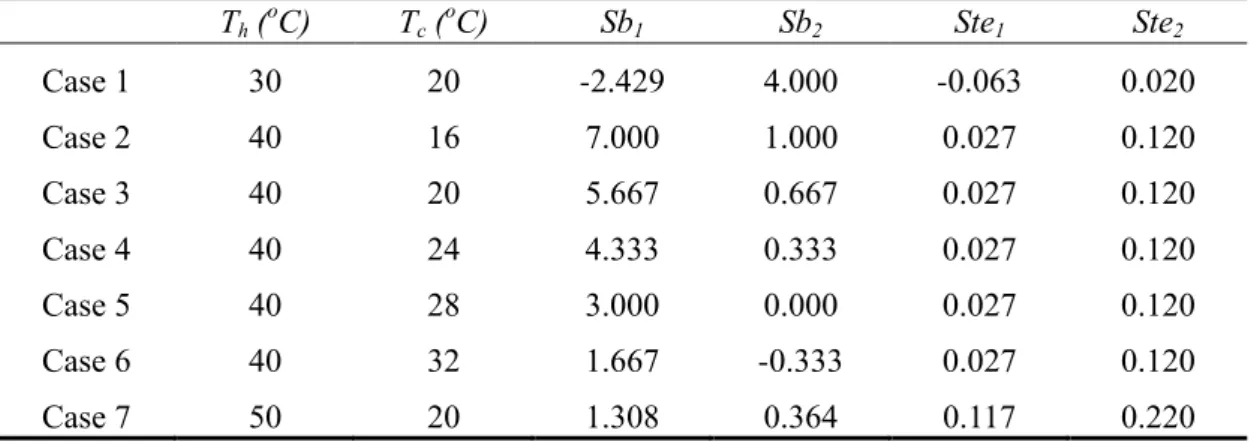
Table 1 Parametric ranges of studied cases in this work (TM1=37℃,TM2=28℃) (H1=15mm, H2=15mm, λ=1.0)
Th (oC) Tc (oC) Sb1 Sb2 Ste1 Ste2
Case 1 30 20 -2.429 4.000 -0.063 0.020
Case 2 40 16 7.000 1.000 0.027 0.120
Case 3 40 20 5.667 0.667 0.027 0.120
Case 4 40 24 4.333 0.333 0.027 0.120
Case 5 40 28 3.000 0.000 0.027 0.120
Case 6 40 32 1.667 -0.333 0.027 0.120
Case 7 50 20 1.308 0.364 0.117 0.220
Table 2 Parametric ranges of studied cases in this work (TM1=37℃,TM2=28℃) (Th=40℃, Tc=20℃, Sb1=5.667, Sb2=0.667, Ste1=0.027, Ste2=0.120)
H1 (mm) H2 (mm) λ
Case 8 10 20 0.5
Case 3 15 15 1.0
Case 9 20 10 2.0
Case 10 0 30 -
Case 11 30 0 -
Computer Data Acquisition
System
Constant Temperature Bath Test Cell
Thermocouples Data
Data Storage Connecting to
Electrical Heaters
Connecting to Compensative Heater DC Power Supply
Connecting to Low Temperature Wall (a)
x y
L H
H1
H2
HAl
δA
MEPCM, TM1
MEPCM, TM2
Acrylic
o
τ =0 T=Tc; τ >0 T=Th
τ ≥0 T=Tc
(b)
Fig.1 Schematic diagrams of (a) the experimental system and (b) numerical modelling
(a) (b) (c)
Fig.2 Effects of hot wall temperature on temporal variations of dimensionless accumulated energy. (a) Accumulated energy through hot wall, (b) Accumulated energy through cold wall, (c) Net energy stored in
the enclosure
(a) (b) (c)
Fig.3 Effects of cold wall temperature on temporal variations of dimensionless accumulated energy.
(a) Accumulated energy through hot wall, (b) Accumulated energy through cold wall, (c) Net energy stored in the enclosure
(a)
TM1=37℃, TM2=28℃
Th=40℃, Tc=20℃
Ste1=0.027, Sb1=5.667 Ste2=0.120, Sb2=0.667
(b)
TM1=37℃, TM2=28℃
Th=40℃, Tc=20℃
Ste1=0.027, Sb1=5.667 Ste2=0.120, Sb2=0.667
(c)
TM1=37℃, TM2=28℃
Th=40℃, Tc=20℃
Ste1=0.027, Sb1=5.667 Ste2=0.120, Sb2=0.667
Fig.4 Effects of partitioned ratio λ on temporal variations of dimensionless accumulated energy.
(a) Accumulated energy through hot wall, (b) Accumulated energy through cold wall, (c) Net energy stored in the enclosure
(a)
Pure TM=28℃
Pure TM=37℃
TM1=37℃, TM2=28℃
Th=40℃, Tc=20℃
Ste1=0.027, Sb1=5.667 Ste2=0.120, Sb2=0.667
Pure TM=28℃
Pure TM=37℃
(b)
TM1=37℃, TM2=28℃
Th=40℃, Tc=20℃
Ste1=0.027, Sb1=5.667 Ste2=0.120, Sb2=0.667
(c)
Pure TM=28℃
Pure TM=37℃
TM1=37℃, TM2=28℃
Th=40℃, Tc=20℃
Ste1=0.027, Sb1=5.667 Ste2=0.120, Sb2=0.667
Fig.5 Comparison of temporal variations of dimensionless accumulated energy in enclosures with/without partitions. (a) Accumulated energy through hot wall, (b) Accumulated energy through cold wall, (c) Net
energy stored in the enclosure