國立臺灣大學工學院機械工程學系 碩士論文
Graduate Institute of Mechanical Engineering College of Engineering
National Taiwan University Master Thesis
具運動相容性之重力平衡手肘外骨骼設計
Synthesis of Kinematic Compatible Gravity Balanced Elbow Exoskeletons
莊其勳
Qi-Xun Zhuang
指導教授:陳達仁 博士 Advisor: Dar-Zen Chen, Ph.D.
中華民國 105 年 7 月
July, 2016
摘要
運動相容性為使用外骨骼運動過程中,上肢與外骨骼之連接桿件不會產生相 對位移。本論文提出具運動相容性之重力靜平衡上肢外骨骼的設計方法。將上肢 與外骨骼之連接桿件定義為同一桿件形成一封閉迴路,安裝外骨骼前後之運動自 由度相等,計算可得外骨骼接頭自由度之總和與上肢運動自由度相等,上肢運動 自由度為上肢之平移與旋轉自由度之總合,外骨骼接頭之位置、方向與上肢相 同。限制在不同運動自由度下使用之接頭種類、數量與排列順序可得具有及非具 有提攜角之手肘、肩膀、手臂所有型態之外骨骼。由上肢運動範圍可得外骨骼之 桿件長度。系統中總位能不隨機構運動改變即達到重力靜平衡,不同提攜角下彈 簧安裝位置不同,以平均提攜角計算手肘外骨骼對應之彈簧彈性係數、彈簧安裝 位置。提攜角造成彈簧在相異平面而對外骨骼產生偏擺、翻轉力矩,以 adams 模 擬上肢具提攜角使用外骨骼作垂直面及水平面手肘屈伸運動下外骨骼承受之偏 擺、翻轉力矩,驗證外骨骼應用之可行性。
關鍵字:外骨骼、運動相容性、重力平衡、肩膀、手肘
Abstract
In this thesis, a design methodology of kinematic compatible and gravity balanced exoskeleton is presented. Kinematic compatibility is human using exoskeleton, relative motion between human arm and attachment links of exoskeleton does not exist. By taking human arm and attachment links of exoskeleton as the same links, human arm and exoskeleton becomes a close loop. And the operating degree-of-freedoms before and after installing exoskeleton to human arm must equal to each other. By Gruebler's equation, sum of degree-of-freedom(DOF) of exoskeleton joints equals to the operating degree-of-freedom of human arm. Operating degree-of-freedom of human arm is sum of number of rotation axes and translation axes of human arm. Location and orientation of exoskeleton joints are parallel to rotation axes and translation axes of human arm.
Limiting numbers, kinds and series of exoskeleton joint in different operating degree-of- freedom of human arm gets all possible exoskeletons for elbow with or without carrying angle, shoulder and arm. By range of motion of human arm determining length of exoskeleton links. Carrying angle effects spring attachment locations, using mean carrying angle determining spring constants, spring attachment locations and yaw and roll torques on exoskeleton since springs are on different rotation planes. Simulation by adams determines the yaw and roll torques on exoskeleton joints in elbow with carrying
angle in flexion-extension motion in sagittal and transverse planes to verify feasibility of kinematic compatible gravity balanced elbow exoskeleton.
Keywords: Exoskeleton, kinematic compatibility, gravity balancing, shoulder, elbow
Contents
Chapter 1 Introduction ... 1
1.1. Relative motions between human limb and exoskeleton attachment links ... 1
1.2. Human limb axes moving with motions... 3
1.3. Previous works ... 7
1.4. Motivation ... 9
Chapter 2 Kinematic Compatibility ... 11
Chapter 3 Elbow, Shoulder and Arm Exoskeletons ... 15
3.1. Elbow with negligible carrying angle exoskeletons ... 15
3.2. Elbow with significant carrying angle exoskeletons ... 17
3.3. Elbow with significant carrying angle and forearm axial rotation exoskeletons ... 19
3.4 Shoulder Exoskeletons ... 20
3.5 Arm exoskeletons ... 22
Chapter 4 SRRP Elbow Exoskeleton ... 25
4.1 Links length of SRRP elbow exoskeleton ... 25
4.2 Gravity balancing of SRRP elbow exoskeleton ... 29
4.3 Prototype of SRRP elbow exoskeleton ... 39
Chapter 5 Results and Discussions of Simulations of Yaw and Roll Torques ... 41
5.1 Yaw and roll torques on exoskeleton joints for elbow flexion-extension motion in sagittal plane ... 41
5.2 Yaw and roll torques on exoskeleton joints for elbow flexion-extension motion in transverse plane ... 44
Chapter 6 Conclusions and Future Works ... 47
6.1 Conclusions ... 47
6.2 Future works ... 48
References ... 49
List of Figures
Fig. 1 Exoskeletons for medical treatments, military, and activities of daily living. (a) Armin II (image adopted from (T. Nef, 2008)) (b) leg orthosis (image adopted from (Banala, 2006)) (c) BLEEX (image adopted from (Kazerooni, 2006)) (d) mobile arm support (image adopted from (Herder, 2006)) ... 3 Fig. 2 Cardinal planes of the human body. (image adopted from (Hanmill and Knutzen
2006)) ... 5 Fig. 3 Human body structuresHuman body structures. (image adopted from. (a)
shoulder complex (b) elbow complex (Gopura and Kiguchi, 2009)) ... 5 Fig. 4 Scapula movements and rotations of the glenohumeral joint (image adopted from
(Yalcin, 2012)) ... 6 Fig. 5 Human arm with carrying angle (image adopted from (Roy et al, 2005))... 7 Fig. 6 Spatial kinematic compatible mechanisms (a) spherical four bar linkage (image
adopted from image adopted from (Bergamasco, 1994)) (b) 3PRR (image adopted from (Carignan et al, 2005)) (c) PRR (image adopted from (Nef et al, 2009)) ... 8 Fig. 7 Planar kinematic compatible mechanisms (a) PPR (image adopted from image
adopted from (Stienen et al, 2009)) (b) 3PRR (image adopted from (Yalcin and Patoglu, 2012)) (c) PRR (image adopted from (Cempini et al, 2013)) ... 9 Fig. 8 Human skeletal systems connect with exoskeleton ... 13 Fig. 9 Rotation axes and translation axes of human limb (a) elbow complex (b) shoulder complex ... 13 Fig. 10 Types of exoskeletons of elbow with negligible carrying angle ... 17 Fig. 11 Types of exoskeletons of elbow with significant carrying angle ... 18 Fig. 12 Cardinal planes of the human body. (image adopted from (Hanmill and Knutzen
2006)) ... 20 Fig. 13 Types of shoulder exoskeleton ... 22 Fig. 14 Types of arm exoskeleton ... 24
Fig. 15 Elbow exoskeleton attached with exoskeleton (a) isometric view (b) right view of elbow flexion angle = 0 (deg) (c) right view of pronation angle = 85 (deg) 27 Fig. 16 Support and elbow exoskeleton (a) elbow flexion extension motion in sagittal
plane (b) elbow flexion extension motion in transverse plane (c) Support for gravity balancing of whole system ... 31 Fig. 17 (a)Gravity potential energy of human arm and exoskeleton (b) Spring
installation configuration of the elbow exoskeleton for elbow with carrying angle ... 34 Fig. 18 Prototype (a) CAD of elbow exoskeleton (b) prototype of elbow exoskeleton (c)
adjustment screw and spring in support (d) springs and exoskeleton (e)
adjustment screw in exoskeleton ... 40
List of Tables
Table 1 Dimensional and inertia parameters ... 29
Table 2 Dimensional and inertia parameters of the support... 32
Table 3 Dimensional and inertia parameters ... 35
Table 4 Spring design parameters of the elbow exoskeleton ... 37
Table 5 Yaw and roll torque on exoskeleton joints in elbow extension-flexion motion in sagittal plane ... 42
Table 6 Yaw and roll torque on exoskeleton joints in elbow extension-flexion motion in transverse plane ... 44
Chapter 1 Introduction
1.1. Relative motions between human limb and exoskeleton attachment links
An exoskeleton is a device attached to a human limb to support, assist or enhance that limb. As shown in Fig. 1, different designs of exoskeletons in many researches are for different purposes like medical treatments, e.g. WREX, a five degrees-of-freedom functional orthosis for patients with neuromuscular diseases [1]; T-WREX is an adult- sized version WREX [2]; Armin ii(Fig. 1(a)) is a shoulder actuation mechanisms for arm rehabilitation exoskeleton [3]; Dampace can automatically align its rotation axes to human anatomical axes avoiding patient feel painful when they using exoskeleton [4];
leg orthosis (Fig. 1(b)) to assist persons with hemiparesis to walk [5]; a seven-degrees- of-freedom upper limb exoskeleton for task-based occupational or physical therapy for patients [6], military uses, e.g. BLEEX(Fig. 1(c)), a lower extremity exoskeleton can provide soldiers, disaster relief workers, wildfire fighters, and other emergency
personnel with the ability to carry heavy loads such as food, rescue equipment, first-aid supplies, communications gear, and weaponry, without the strain typically associated with demanding labor [7], e.g. a spring-balanced mobile arm support(Fig. 1(d)) for
people with muscular weakness based on the biomechanical principle can perform basic activities of daily living [8] and others. In any field, an exoskeleton should have
kinematic compatibility to a human limb. More specifically, a kinematic compatible exoskeleton which kinematic characteristic and range of motion covers which of the endoskeleton of human. And an exoskeleton achieves kinematic characteristic and the range of motion of human limb with its least degree of freedom. A kinematic
incompatible exoskeleton makes relative motion between human limb and exoskeleton attachment links. Relative motion makes slip force which makes friction between human limb and exoskeleton attachment links acting on human limb and user feel discomfort.
Fig. 1 Exoskeletons for medical treatments, military, and activities of daily living. (a) Armin II (image adopted from (T. Nef, 2008)) (b) leg orthosis (image adopted from (Banala, 2006)) (c) BLEEX (image adopted from (Kazerooni, 2006)) (d) mobile arm support (image adopted from (Herder, 2006))
1.2. Human limb axes moving with motions
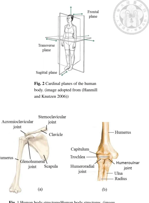
As shown in Fig. 2, the cardinal planes of the human body is introduced to be easier referred to while describing the motion of the body [9]. The frontal plane divides the body into front and back, the sagittal plane divides the body into right and left; and the transverse plane divides the body into top and bottom. Human endoskeleton system is complex causing exoskeleton hard to achieving kinematic compatible. Direct joint manipulation on exoskeleton can be achieved when each of joint axes of actuating joints
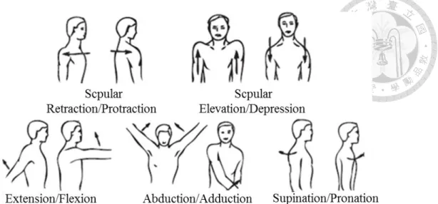
in the exoskeleton is always aligned with the rotation axis of human joint. However, this is difficult due to the complex movements of human joint, e.g. the shoulder joint and the elbow joint, for anatomic and biomechanical reasons. As shown in Fig. 3(a), shoulder complex consists of three bones, the clavicle, scapula and humerus, and three
articulations, sternoclavicular joint, glenohumeral joint and acromioclavicular joint [10].
Shoulder joint movements is complex and it can be resulted from the movements of the scapula and the rotations of the glenohumeral joint [11]. As shown in Fig. 4, scapula movements are known as the protraction-retraction and elevation-depression, and three rotations of the glenohumeral joints known as the flexion-extension, abduction-
adduction, and supination-pronation [12]. The abduction-adduction, elevation-
depression movements of scapula are independent with respect to the configuration of the upper arm and the upward-downward rotation of scapula occurs passively only when the upper arm is elevated. The glenohumeral joint is not a fixed joint during the upper arm movements since it is a synovial joint at the articular point of the humerus and the scapula.
Fig. 2 Cardinal planes of the human body. (image adopted from (Hanmill and Knutzen 2006))
Fig. 1 Human body structuresHuman body structures. (image
adopted from. (a) shoulder complex (b) elbow complex (Gopura and Kiguchi, 2009))
As shown in Fig. 3(b), elbow complex is a compound joint consists of three bones, humerus, ulna and radius, and two articulations, one is the humeroradial between the capitulum and radius, the other is the humeroulnar between the trochlea and the ulna [10]. The elbow complex allows 2DOF motion: flexion-extension and supination- pronation motions. As shown in Fig. 5, elbow joint has carrying angle caused by angle between axes of humerus and forearm making upper arm axis and forearm axis are not pararllel [13]. This angle difference in any person and progressively decreased with elbow flexion makes rotation axis of elbow not fixed. Moreover, it is still difficult to predict the exact location of joint center in real world without image recording devices, e.g. glenohumeral joint [12, 14]. Therefore, modeling glenohumeral joint as a ball-and- socket joint and elbow joint as a revolute joint are not precise since position or rotation axis of joint center is changing constantly in the biomechanical interpretation i.e. center
Fig. 2 Scapula movements and rotations of the glenohumeral joint (image adopted from (Yalcin, 2012))
of joint is difficult to track. Consequently, designs of exoskeleton inevitably face the challenges of the kinematic compatibility.
1.3. Previous works
Current exoskeletons deal with the aforesaid problems by using different ways.
Aligning axes of exoskeleton and human, as shown in Fig. 6, using spherical four bar linkage to facilitate kinematic compatibility of shoulder [15](Fig. 6(a)). But the center of spherical four bar linkage is fixed, suffering the aforementioned problems because human axes moving with motions and leading limitation of range of motion of human arm when the exoskeleton attached to human arm. Adding an additional revolute joint to lead the center of spherical four bar linkages can move along an arc locus [16](Fig.
6(b)). The ARMin III(Fig. 6(c)) uses lifting column to allow the center of spherical 4- Fig. 3 Human arm with carrying angle
(image adopted from (Roy et al, 2005))
bar linkage moves vertically to trace the center of glenohumeral joint [17]. These exoskeletons trace spatial movements of human joint, however, movements of shoulder and elbow are not simple to model them to a revolute joint or prismatic joint because human joints are not perfect joints. Accurate aligning joints of exoskeleton with human joints during installing exoskeleton on human and human arm motions is difficult.
Cempini et al presented a general analytical method by solving the kinematic closure equation to analyze a exoskeleton having kinematic compatibility or not [18]. However, closure equation may too difficult to solve and it is not a design methodology.
Accurately aligning axes of exoskeleton and human is almost impossible, another method dealing with kinematic compatibility problem is auto compensation. As shown in Fig. 7, adding two prismatic joints makes exoskeleton joint having additional free translation DOF so that exoskeleton automatically compensate distance between its
Fig. 6 Spatial kinematic compatible mechanisms (a) spherical four bar linkage (image adopted from image adopted from (Bergamasco, 1994)) (b) 3PRR (image adopted from (Carignan et al, 2005)) (c) PRR (image adopted from (Nef et al, 2009))
joint and human joint [4](Fig. 7(a)), using 3RRP mechanism allows exoskeleton joint can compensate distance between joints in planar [12](Fig. 7(b)), and PRR also can deal with planar kinematic compatibility [19](Fig. 7(c)). These exoskeletons trace planar movements of human joint, however, using two prismatic joints makes friction problem during human arm motions and exoskeleton attaching to human arm with multiple links, auto compensation method does not suit for exoskeletons.
1.4. Motivation
In this thesis, defining kinematic compatibility is human using exoskeleton,
relative motion between human arm and attachment links of exoskeleton does not exist.
A design methodology of kinematic compatible and gravity balanced exoskeleton is presented. Defining kinematic compatibility is human using exoskeleton, relative
motion between human arm and attachment links of exoskeleton does not exist. human Fig. 7 Planar kinematic compatible mechanisms (a) PPR (image adopted from image adopted from (Stienen et al, 2009)) (b) 3PRR (image adopted from (Yalcin and Patoglu, 2012)) (c) PRR (image adopted from (Cempini et al, 2013))
arm and exoskeleton becomes a close loop. And the operating degree-of-freedoms before and after installing exoskeleton to human arm must equal to each other. By Gruebler's equation, sum of degree-of-freedom of exoskeleton joints equals to the operating degree-of-freedom of human arm. Operating degree-of-freedom of human arm is sum of number of rotation axes and translation axes of human arm. Location and orientation of exoskeleton joints are parallel to rotation axes and translation axes of human arm. Limiting numbers, kinds and series of exoskeleton joint in different operating degree-of-freedom of human arm gets all possible exoskeletons for elbow with or without carrying angle, shoulder and arm. By range of motion of human arm determining length of exoskeleton links. Carrying angle effects spring attachment locations, using mean carrying angle determining spring constants, spring attachment locations and yaw and roll torques on exoskeleton since springs are on different rotation planes. Simulation by adams determines the yaw and roll torques on exoskeleton joints in elbow with carrying angle in flexion-extension motion in sagittal and transverse planes to verify feasibility of kinematic compatible gravity balanced elbow exoskeleton.
Chapter 2
Kinematic Compatibility
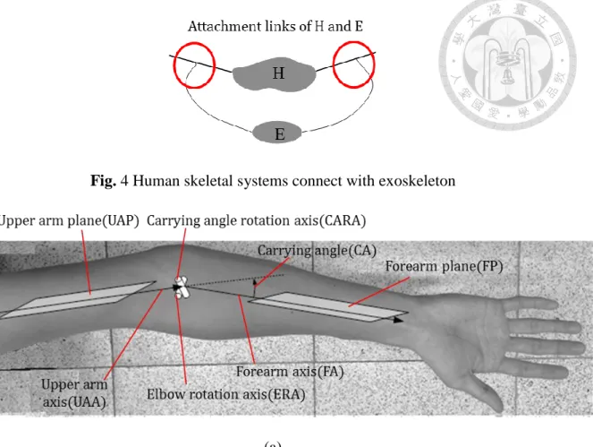
As shown in Fig. 8, human limbs, H, attached with exoskeleton, E. Assuming attachment links of H, E are the same link. Relative motion does not exist between attachment links of H and E i.e. slip force and friction do not exist between attachment links of H and E. Exoskeleton achieves kinematic compatibility. Degree-of-freedoms of human limbs equals to which of human limbs attached with exoskeleton.
By following Gruebler's equation as
λ(n − j − 1) + ∑ fi)H+ ∑ fi)E= λH(nH− jH− 1) + ∑ fi)H (1)
where 𝑛H, 𝑗h, ∑𝑓𝑖)𝐻, 𝜆𝐻, and ∑𝑓𝑖)E are number of links, number of joints, sum of DOF of human joints, operating DOF of human segments, and sum of DOF of exoskeleton joints. 𝑛, 𝑗, and 𝜆 are number of links, number of joints, and operating DOF of human segments attached with exoskeleton.
H and E forms a close loop. Number of links, number of joints, and operating DOF of human segments have relations to which of human segments attached with exoskeleton
as following equations
λ = λH (2)
n = nH+ nE− 2 (3)
𝑗 = 𝑗𝐻+ 𝑗𝐸 (4)
where 𝑛E and 𝑗E, are number of links and number of joints of exoskeleton.
Substituting (2) (3) (4) into (1) yields
∑ fi)E= (2 + 𝑗𝐸 − 𝑛𝐸)𝜆𝐻 (5)
Since the number of links and number of joints of exoskeleton arepositive integer, Eq.
(5) can be rewritten as
∑ fi)E= aλH (6)
Sum of DOF of exoskeleton joints equals to a times of operating DOF of human
segments, and in general, a=1 for exoskeleton design such that eq.(6) becomes
∑ fi)E= λH (7)
According to operating DOF of human segments, 𝜆𝐻, defining corresponding axes and planes of arm to select position and orientation of joints
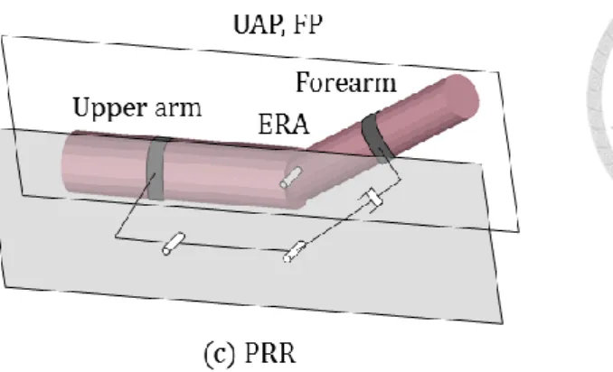
As shown in Fig. 9, for elbow flexion-extension motion, the rotation motion plane is called forearm plane (FP) which contains forearm axis (FA) and elbow rotation axis (ERA) which is perpendicular to FP, the axis normal to ERA and FA is called carrying angle rotation axis (CARA), and the plane with carrying angle from FP is called upper arm plane (UAP) which contains upper arm axis (UAA).
(a)
(b)
Synthesis of admissible exoskeletons for kinematic compatibility are presented by following rules
R1: Joint must be on the plane parallel to operating plane of human limb, and its Fig. 4 Human skeletal systems connect with exoskeleton
Fig. 5 Rotation axes and translation axes of human limb (a) elbow complex (b) shoulder complex
translation or rotation direction must be parallel to axis of human limb.
R2: Series of exoskeleton joints can be reversed and order of R joint can be changed.
R3: For operating DOF of human limb is greater than or equal to four, 𝜆𝐻≥ 5, it does not use pin in slot.
R4: Use maximum one prismatic joint or pin in slot.
R5: Pin in slot or prismatic joint is not in the middle of series of exoskeleton.
R6: Use revolute joint as middle joint of exoskeleton R7: For arm exoskeleton, it must use prismatic joint
Rule 1-3 are about operating DOF of human limb, 𝜆𝐻, for limiting positions and combinations of exoskeleton joints. Rule 4-5 are about avoiding friction effects by prismatic joint or pin in slot. Rule 6-7 are about avoiding arm exoskeleton becoming too complex.
Chapter 3
Elbow, Shoulder and Arm Exoskeletons
3.1. Elbow with negligible carrying angle exoskeletons
Three types of elbow exoskeletons are presented. One is for elbow with negligible carrying angle, another is for elbow with carrying angle, and the other is for elbow with carrying angle and forearm axial rotation. First case: exoskeleton for elbow with
negligible carrying angle, the operating DOF of elbow is three which are translation DOF of upper arm axis and forearm axis, and rotation DOF of elbow rotation axis. Sum of DOF of exoskeleton joints equaling to operating DOF of elbow is three, and using revolute joint, prismatic joint, and pin in slot for designing exoskeleton. According to rule 1-2, 4-5, revolute joint, prismatic joint, and pin in slot are on the plane parallel to forearm plane, rotation axis of revolute joint and pin of pin in slot is parallel to elbow rotation axis, and translation direction of prismatic joint and slot of pin in slot is parallel to upper arm axis or forearm axis, and using maximum one prismatic joint or pin in slot, and prismatic joint or pin in slot is not in the middle of series of exoskeleton. The combinations of revolute joint, prismatic joint, and pin in slot are shown as Fig. 10, and series of exoskeleton joints can be reversed and order of R joint can be changed, in which, (b) RRR and (c) RRP are the same mechanisms to [19] who presented RRR(Fig.
10(b)), RPR, PRR(Fig. 10(c)), PPR four mechanisms ends with revolute joint since these four mechanisms designed as underactuated systems. However the mechanisms only use 1 DOF joint, R pin in slot is also a solution as shown in Fig. 10(a). And [12]
using 3RRP mechanism allows exoskeleton joint can align with joint in planar, which is added 2RRP to original RRP mechanism to have strong structure.
RRR need longer links to avoid collision with arm since revolute joint is not like prismatic joint which has translation DOF, R pin in slot and RRP have translation DOF for suiting different arm length easily, but slot of pin in slot cannot adjust link length like drawer slider.
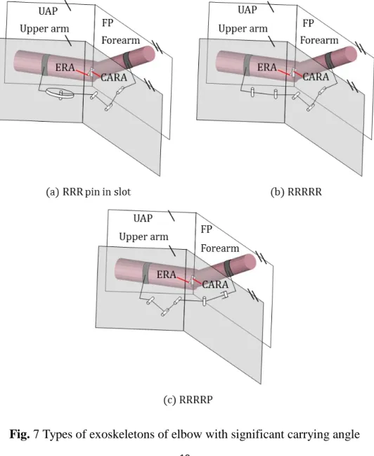
3.2. Elbow with significant carrying angle exoskeletons
Second case: exoskeleton for elbow with carrying angle, the operating DOF of elbow is five which are translation DOF of upper arm axis and forearm axis, and rotation DOF of elbow rotation axis and carrying angle rotation axis. Sum of DOF of exoskeleton joints equaling to operating DOF of elbow is five, and also using revolute joint, prismatic joint, and pin in slot for designing exoskeleton. According to rule 1-2, 4- 5, revolute joint, prismatic joint, and pin in slot are on the plane parallel to upper arm plane or forearm plane, rotation axis of revolute joint and pin of pin in slot is parallel to elbow rotation axis or carrying angle rotation axis, and translation direction of prismatic joint and slot of pin in slot is parallel to upper arm axis or forearm axis, and using maximum one prismatic joint or pin in slot, and prismatic joint or pin in slot is not in the middle of series of exoskeleton. The combinations of revolute joint, prismatic joint, and pin in slot are shown as Fig. 11, and series of exoskeleton joints can be reversed and
Fig. 6 Types of exoskeletons of elbow with negligible carrying angle
order of R joint can be changed.
Pin of RRR pin in slot offer rotation DOF of carrying angle rotation axis, but it may be effected by friction since elbow flexion-extension motion with carrying angle is spatial motion, RRRRR and RRRRP do not suffer this problem. RRRRP has a prismatic joint for suiting different user arm, it is better than RRRRR which needs longer links in last two links. These mechanisms have more kinematic compatibility than just using one revolute joint or planar mechanism for elbow in designing exoskeleton.
Fig. 7 Types of exoskeletons of elbow with significant carrying angle
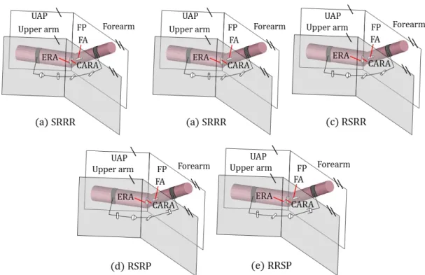
3.3. Elbow with significant carrying angle and forearm axial rotation exoskeletons
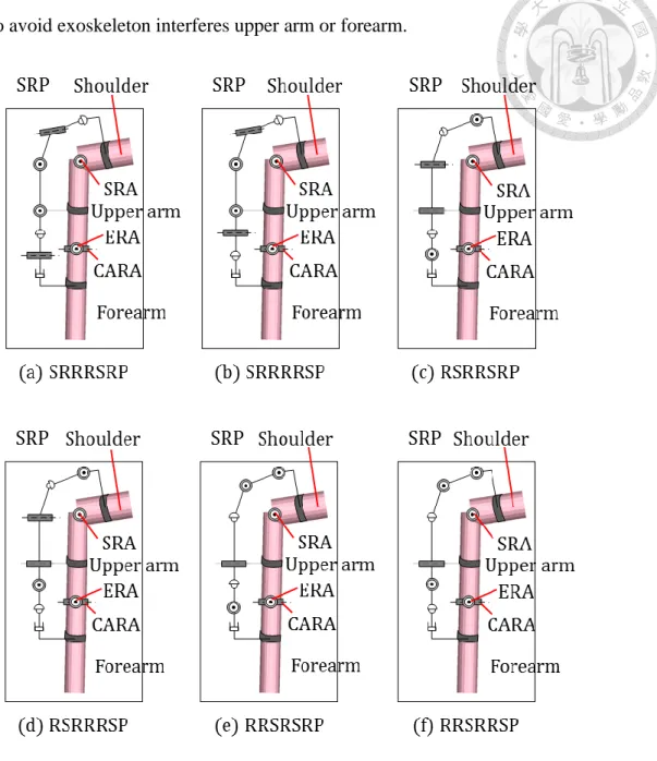
Third case: exoskeleton for elbow with carrying angle and forearm axial rotation, the operating DOF of elbow is six which are translation DOF of upper arm axis and forearm axis, and rotation DOF of elbow rotation axis, carrying angle rotation axis, and forearm axis. Sum of DOF of exoskeleton joints equaling to operating DOF of elbow is six, and using revolute joint, prismatic joint, and spherical joint for designing
exoskeleton. According to rule 1-5, revolute joint, prismatic joint, and spherical joint are on the plane parallel to upper arm plane or forearm plane, rotation axis of revolute joint is parallel to elbow rotation axis or carrying angle rotation axis, and translation direction of prismatic joint is parallel to upper arm axis or forearm axis and translation direction of prismatic joint and slot of pin in slot is parallel to upper arm axis or forearm axis, and using maximum one prismatic joint, and prismatic joint is not in the middle of series of exoskeleton. The combinations of revolute joint, prismatic joint, and spherical joint are shown as Fig. 12, and series of exoskeleton joints can be reversed and order of R joint can be changed. SRRR and RSRR do not have prismatic joint in exoskeleton, they need longer links to avoid exoskeleton interfere human arm. SRRP, RSRP, and RRSP have a prismatic joint which offer a translational DOF, suit for human arm motion. Spherical
joint of RSRP and RRSP are on the middle of series of exoskeleton, easily connect different of rotation axis and translational direction of other joints, however, they cannot make other joints moving with human arm motion. Spherical joint of SRRP is on first series of exoskeleton, making RRP joints moving with elbow doing flexion-extension motion.
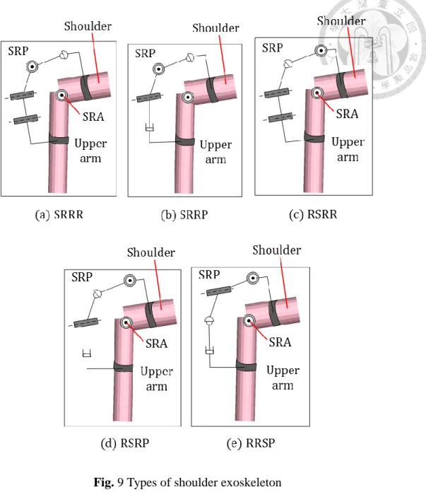
3.4 Shoulder Exoskeletons
Forth case: exoskeleton for shoulder complex, the operating DOF of shoulder complex is six, which are translation DOF ofshoulder axis, upper arm axis, and shoulder rotation axis and rotation DOF of shoulder axis, upper arm axis, and shoulder
Fig. 8 Cardinal planes of the human body. (image adopted from (Hanmill and Knutzen 2006))
rotation axis. Sum of DOF of exoskeleton joints equaling to operating DOF of elbow is six, and also using revolute joint, prismatic joint, and spherical joint for designing exoskeleton. According to rule 1-5, revolute joint, prismatic joint, and spherical joint are on upper arm plane or shoulder rotation plane, rotation axis of revolute joint is parallel to shoulder axis, upper arm axis, and shoulder rotation axis, and translation direction of prismatic joint is parallel to shoulder axis, upper arm axis, and shoulder rotation axis.
The combinations of revolute joint, prismatic joint, and spherical joint are the same to third case, exoskeleton for elbow with carrying angle and forearm axial rotation, since shoulder and elbow with carrying angle and forearm axial rotation both have three independent rotation axes and translation directions, and results are shown as Fig. 13, and series of exoskeleton joints can be reversed and order of R joint can be changed.
For three rotation axes of shoulder complex, SRRR and SRRP are better than other exoskeletons, RSRR, RSRP, and RRSP because spherical joints of SRRR and SRRP are on first series of exoskeletons which make exoskeletons can rotation with shoulder complex and avoid exoskeletons have collision with human arm, first joints of RSRR, RSRP, and RRSP are revolute joint, it just suit for one rotation axis, for motions of other two rotation axes, it needs longer link to avoid exoskeletons interfere human arm. SRRP has a prismatic joint to suit for different upper arm length of users, which is better than SRRR because SRRR needs longer links to suit for shoulder motions.
3.5 Arm exoskeletons
Fifth case: exoskeleton for shoulder complex and elbow with carrying angle and forearm axial rotation, the operating DOF of shoulder complex is eleven, which are translation DOF ofshoulder axis, upper arm axis, shoulder rotation axis, forearm axis, and carrying angle rotation axis and rotation DOF of shoulder axis, upper arm axis,
Fig. 9 Types of shoulder exoskeleton
shoulder rotation axis, elbow rotation axis, forearm axis, and carrying angle rotation axis. Sum of DOF of exoskeleton joints equaling to operating DOF of elbow is eleven, and using revolute joint, prismatic joint, and spherical joint for designing exoskeleton.
According to rule 1-7, revolute joint, prismatic joint, and spherical joint are on upper arm plane or shoulder rotation plane, rotation axis of revolute joint is parallel to
shoulder axis, upper arm axis, shoulder rotation axis, elbow rotation axis, forearm axis, and carrying angle rotation axis, and translation direction of prismatic joint is parallel to shoulder axis, upper arm axis, shoulder rotation axis, forearm axis, and carrying angle rotation axis. The combinations of revolute joint, prismatic joint, and spherical joint are shown as Fig. 14, and series of exoskeleton joints can be reversed and order of R joint can be changed. For motions of shoulder, first joints of RSRRSRR, RSRRSRP,
RSRRRSP, RRSRSRP, and RRSRRSP are revolute joint, which cannot offer all rotations DOF for rotation motions of shoulder such that SRRRSRR, SRRRSRP, and SRRRRSP are better since their first joints are spherical joint. For suiting different forearm length of users, SRRRSRP and SRRRRSP having prismatic joint are better than SRRRSRR which needs longer links to avoid exoskeleton having collision with
forearm. For motions of elbow, with the same reason to motions of shoulder, second spherical joint of SRRRSRP making the last two joints moving with elbow flexion- extension motion, is better than SRRRRSP which also needs longer links for revolute
joint to avoid exoskeleton interferes upper arm or forearm.
Fig. 10 Types of arm exoskeleton
Chapter 4
SRRP Elbow Exoskeleton
4.1 Links length of SRRP elbow exoskeleton
Design a kinematic compatible exoskeleton prototype, for shoulder exoskeleton, there are many exoskeleton have been designed in other researches, but for elbow exoskeleton, most of design only using one revolute joint to suit elbow flexion- extension motion, however, it just suit for elbow with negligible carrying angle i.e.
elbow flexion-extension motion which is a planar motion. Elbow joint has carrying angle which makes elbow flexion-extension motion become a spatial motion. In this thesis, designing SRRP exoskeleton for elbow with/without carrying angle which range is form 0 to 20 degrees in elbow flexion angle is 0 degree [13], elbow flexion-extension motion and forearm axial rotation i.e. pronation-supination motion which range are form 0 to 140 and 85 to 90 degrees, respectively [16].
For both elbow flexion-extension and pronation-supination motion, in motion, upper arm plane and forearm plane have large relative rotation. RRR mechanism needs longer link length avoiding collision between limbs and exoskeleton [19], using RRRP mechanism to achieve kinematic compatibility [20], however, it just suits for elbow without carrying angle. Spherical joint which leads others joint to rotate with forearm
suits for first joint in kinematic compatible elbow exoskeleton, elbow rotation axis and various carrying angle, two revolute joints suits in middle series of exoskeleton, and prismatic joint adapting different length of forearm is the last joint in exoskeleton.
SRRP exoskeleton is better than other type of elbow exoskeletons.
(a)
(b)
(c)
As shown in Fig. 15(a), forearm plane be parallel to vertical plane, elbow exoskeleton attached to side of arm, and the distance between arm and elbow
exoskeleton is d (cm). This distance must larger than radius of upper arm and forearm, and an appropriate distance make exoskeleton does not have collision with human arm.
Diameter range of upper arm, 𝑑𝑢 and forearm, 𝑑𝑓 are respectively from 0.06 to 0.1 (m) and from 0.06 to 0.08 (m) [21, 22], distance between arm and elbow exoskeleton is effected by diameter range of upper arm and forearm, width of link, and tolerance as
following equation
width of link tolerance 2
du
d
(8) where maximum of diameter of upper arm is 0.1 (m), width of link is 0.01 (m), and let tolerance is 0.02 (m), than the distance between arm and elbow exoskeleton, d, equal to
0.08 (m).
Upper arm and forearm length of users are different, for easier design link length of elbow exoskeleton, using mean length of upper arm and forearm which are 0.25, 0.25 (m) [23], and let attachment points are the middle points of upper arm and forearm, the distance of attachment points and upper arm, forearm,Lua, Lfa are 0.125 (m). For
Fig. 11 Elbow exoskeleton attached with exoskeleton (a) isometric view (b) right view of elbow flexion angle = 0 (deg) (c) right view of pronation angle = 85 (deg)
determining limitation of link length of elbow exoskeleton, let elbow joint without carrying angle since which with carrying angle effects the projection of attachment points on forearm plane is shorter than which without carrying angle. For rigidity of elbow exoskeleton, link 1 should not too long, let L1 = 0.06 (m), translation range of prismatic joint is not longer than length of forearm, let L4 = 0.25 (m), and for elbow exoskeleton not easily interfere to upper arm and forearm, length of link 2 and 3 are not too short which would making collision between exoskeleton and upper arm or forearm when revolute joint 1 and 2 rotating, let length of link 2 and 3 are equal, L2 = L3. As shown in Fig. 15(b), flexion-extension of elbow flexion angle is 140 and pronation- supination angle is 0 degree, sum of length of link 2 and link 3 should not longer than translation range of prismatic joint i.e. sum of length of link 2 and link 3 is not longer than the distance between spherical joint and the distal point of forearm in elbow
flexion angle is 140 and pronation-supination angle is 0 degree as following equation
√L42+ (Lua− L1)2− 2L4(Lua− L1)𝑐𝑜𝑠(40) ≥ 𝐿2+ 𝐿3 (9)
Flexion-extension of elbow is 0 and pronation-supination is 90, length of link 2 and link 3 must be longer than distance between arm and elbow exoskeleton, d, and sum of length of link 2 and link 3 should be longer than distance between spherical joint and prismatic joint, and because length of link 2 equals to length of link 3, length of link 2 and link 3 as following equation
2
2 u a 1
2 3
L L
L d
2
L -
(10)
By eq.(9-10), length of link 2 and link 3 both equal to 0.09 (m), and width and depth of each link are 0.01 (m) and 0.03 (m), and material is aluminum which density is 1180 (kg/m2) such that mass of each link mi = 0.35Li (kg), and the weights and lengths of links are shown as Table.1.
4.2 Gravity balancing of SRRP elbow exoskeleton
Gravity balancing for exoskeleton is important because all design purpose of exoskeleton must compensate gravity effects of human limb and exoskeleton to make user offer at least force for moving that limb when use exoskeleton. Two types of gravity balancing are active gravity balancing and passive gravity balancing, most design of exoskeletons using active gravity balancing i.e. using motors to compensate gravity effects of human limb and exoskeleton, however, weight and volume of motor usually cannot be seem as negligible comparing to weight of links or human limb.
Table 1 Dimensional and inertia parameters of the elbow exoskeleton
Fig. 12 Support and elbow exoskeleton (a) elbow flexion extension motion in sagittal plane (b) elbow flexion extension motion in transverse planeTable 2 Dimensional and inertia parameters
of the elbow exoskeleton
Fig. 13 Support and elbow exoskeleton (a) elbow flexion extension motion in sagittal plane (b) elbow flexion extension motion in transverse plane (c) Support for gravity balancing of whole system
Table 3 Dimensional and inertia parameters of the supportFig. 14 Support and elbow
exoskeleton (a) elbow flexion extension motion in sagittal plane (b) elbow flexion extension motion in transverse planeTable 4 Dimensional and inertia parameters
of the elbow exoskeleton
Fig. 15 Support and elbow exoskeleton (a) elbow flexion extension motion in sagittal plane (b) elbow flexion extension motion in
Passive gravity balancing usually using spring to compensate gravity effects, and weight of spring is negligible comparing to weight of links or human limb, is a better way for gravity balancing.
With spring, exoskeleton passively assisting human arm for motions [24]. As shown in Fig. 16(a)(b), two types of elbow exoskeletons for elbow flexion-extension motion in sagittal and transverse planes, the gravity balancing of these two types of elbow exoskeletons is same spring attachment configuration, and mechanism of elbow exoskeletons are nearly the same, only difference of the direction of exoskeleton attachment links.
. (a)
(b)
(c)
Two parts of gravity balancing for elbow exoskeleton, upper arm and forearm, one is the support which balances the whole system consist exoskeleton, upper arm and forearm, the other part is a balancing system for forearm and exoskeleton in elbow flexion-extension motion. First part makes link 1 of exoskeleton maintaining horizontal and suit for different height by using parallelogram [25]. Second part balances the
Fig. 16 Support and elbow exoskeleton (a) elbow flexion extension motion in sagittal plane (b) elbow flexion extension motion in transverse plane (c) Support for gravity balancing of whole system
32
gravity of each link of exoskeleton and forearm in elbow flexion-extension motion in sagittal and transverse planes, and for elbow flexion-extension motion in sagittal plane, carrying angle effecting gravity balancing are negligible; for elbow flexion-extension motion in transverse plane, flexion angle does not affect gravity of exoskeleton, upper arm and forearm.
As shown in Fig. 16(c), the support is a parallelogram to make link 1 of exoskeleton maintaining horizontal. The payload, 𝑚P, is sum of mass of upper arm, forearm and elbow exoskeleton, which range is from 3 to 6 kilograms, 3 ≤ mP≤ 6 (kg). Spring constant, k, and spring attachments a, b can be obtained as
m gs2 2 m gs6 6 m gs4 4 m gl2
k ab
P
(11) where dimensional and inertia parameters of the support i.e. the mass and length of links of support are known as Table 2, and a and b are attachment vectors about spring
i.e. the direction and distance between joint and attachment points, and let 0.075 ≤ a ≤ 0.15, b = 0.15, spring constant, k, is determined by eq.(11), k = 430, and sensitivity of
spring adjustment for weight of arm =
6 3
0.15 0.075 = 0.4(kg/cm) i.e. adjusting spring attachment point for 1 (cm) if the sum mass of upper arm, forearm, and
Table 6 Dimensional and inertia parameters of the support Fig. 177 (a )Gravity potential energy of human arm and exoskeletonTable 7 Dimensional and inertia parameters of the support
Fig. 187 (a )Gravity potential energy of human arm and
exoskeleton become more or less 0.4 (kg). The support balances the whole gravity of the system consisting upper arm, forearm, and exoskeleton. With enough rigidity, gravity balancing of upper arm and forearm by the support does not be effected by carrying angle and elbow flexion-extension motion in sagittal and transverse planes.
Second part balances the gravity of each link of exoskeleton and forearm in elbow flexion-extension motion in sagittal and transverse planes. Range of mass of upper arm and forearm are respectively from 1.5 to 3 (kg) and form 1 to 2 (kg) [23, 26]. As shown in Fig. 17(a), effect of carrying angle affecting gravity is negligible in elbow flexion- extension motion in sagittal plane such that revolute joint 1 does not affect gravity of link 3 because rotation axis of revolute joint 1 is parallel to carrying angle rotation axis, and link 4 is always parallel to forearm, taking link 1 as a ground, link 2 and link 3 as link 5 and link 4 and forearm as link 6, dimensional and inertia parameters of elbow exoskeleton i.e. mass and length of link 5 and 6 is shown as Table 3. First part makes link 1 of exoskeleton maintaining horizontal, gravity potential energy of human arm and exoskeleton shown as the following equation
𝑔𝐾= 𝑚5𝑔12𝐿5𝑠𝑖𝑛 𝜃5+ 𝑚6𝑔𝐿𝑓𝑎𝑠𝑖𝑛 𝜃6 (12)
where θ5 and θ6 are rotation angle of spherical joint and elbow flexion angle, respectively, and Lfa is length of forearm which is 0.125 (m).
(a)
(b)
Fig. 207 (a)Gravity potential energy of human arm and exoskeleton (b) Spring installation configuration of the elbow exoskeleton for elbow with carrying angle
According to gravity potential energy of upper arm, forearm and exoskeleton, which is a function of rotation angle of spherical joint and elbow flexion angle such that elastic potential energy which is to balance gravity potential energy of upper arm, forearm and exoskeleton must be a function of rotation angle of spherical joint and elbow flexion angle because sum of the gravity potential energy of upper arm, forearm, exoskeleton and the elastic potential energy must be constant. To let elastic potential energy is a function of rotation angle of spherical joint and elbow flexion angle, it needs at least two springs to achieve, one is balancing for the gravity of link 5, and the other is balancing for the gravity of link 6. As shown in Fig. 17(b), sum of the gravity potential energy of upper arm, forearm, exoskeleton and the elastic potential energy of two
springs as the following equations, respectively
𝑚5𝑔12𝐿5𝑠𝑖𝑛 𝜃5− 𝑘1𝑎1𝑏1𝑐𝑜𝑠 𝜃1 =0 (𝜃1 = 90 − 𝜃5) (13) 𝑚6𝑔𝐿𝑓𝑎𝑠𝑖𝑛 𝜃6− 𝑘2𝑎2𝑏2𝑐𝑜𝑠 𝜃2 =0 (𝜃2 = 90 − 𝜃6) (14)
where m5, m6, L5, and Lfa are mass of link 5 and 6, and length of link 5 and forearm, k1, k2 are spring constants of spring 1 and 2, a1, b1, a2, b2 are attachment vectors of
Table 10 Dimensional and inertia parameters of the elbow exoskeleton and forearm
Table 11 Spring design parameters of the elbow exoskeletonTable 12 Dimensional and inertia parameters
of the elbow exoskeleton and forearm
spring 1 and 2, and θ1, θ2 are the angle between spring attachment vectors.
For these two springs, the intersection of attachment vectors must be the rotation points i.e. spherical joint and corresponding elbow joint which is the intersection of the link 1 and link 3 because link 1 is parallel to upper arm axis and link 3 is parallel to forearm axis, elbow joint is on the intersection of upper arm axis and forearm axis, for the same reason the intersection of the link 1 and link 3 is the corresponding elbow joint, and having horizontal distance which is also parallel to upper arm axis about
spherical joint, d12, as the following equation
𝑑12 = 𝐿𝑢𝑎− 𝐿1− 𝑑 𝑡𝑎𝑛𝜃2𝑐 (13)
where Lua, L1 and d are the length of upper arm and link 1, and distance between human arm and exoskeleton, and θc is the carrying angle.
Range of carrying angle is from 0 degree to 20 degrees, the range of the distance between spherical joint and corresponding elbow joint as the range of the distance between spherical joint and corresponding elbow joint as substituting 0 ≤ θc ≤ 20 to
eq.(13)
0.063 ≤ 𝑑12 ≤ 0.065 (14)
By eq.(14), it realizes the distance between spherical joint and corresponding elbow joint is effected slightly by carrying angle such that taking corresponding elbow joint as a fixed point since it is not sensitivity in elbow flexion-extension motion in sagittal
plane, and using d12= 0.064 for designing exoskeleton.
Mass of link 5 and 6, and length of link 5 and forearm are known, relation of spring
constants, k1, k2, and spring attachment vectors, a1, a2, as substituting Lfa= 0.0125, L1 = 0.06, m5 = 0.146, 1.3 ≤ m6 ≤ 2.3, L5 = 0.18, b1 = 0.045, b2 = Lfa to
eq.(13-14)
𝑘1𝑎1 = 2.864 (15)
12.753 ≤ 𝑘2𝑎2 ≤ 25.506 (16)
substituting attachment vector of springs are a1 = 0.03 and 0.05 ≤ a2 ≤ 0.1 to eq.(15- 16), getting k1 = 95.5, k2 = 255, and for spring constant 1 is not integer, using and substituting k1 = 100 to eq.(13-14), getting a1 = 0.0286, and sensitivity of spring adjustment for weight of forearm is 2.3 1.3
0.1 0.05
= 0.2 (kg/cm) i.e. adjusting spring attachment point for 1 (cm) if the sum mass of forearm become more or less 0.2 (kg), and the spring design parameters i.e. spring constants and spring attachment vectors of the elbow exoskeleton are shown as Table 4.
Spring 1 is parallel to link 2 and spring 2 is parallel to link 3, and there is an angle Table 13 Spring design parameters of the elbow exoskeleton
between link 2 and link 3 making spring 1 and 2 are on the different plane caused by rotation of revolute joint 1 effected by carrying angle but not equal to carrying angle making spring force 1, 2 and exoskeleton joints are not on the same plane such that exoskeleton joints suffering yaw torque and roll torque which direction are parallel to carrying angle axis and forearm axis in elbow flexion-extension motion in sagittal plane, and parallel to elbow rotation axis and forearm axis in elbow flexion-extension motion in transverse plane. For safety of exoskeleton when user using it, it has to realizes the yaw torque and roll torque.
Yaw torque is product of projection of spring force on transverse plane and distance between joints and projection of spring force on transverse plane, and roll torque is product of projection of spring on front plane, and distance between joints and projection of spring force on front plane, yaw and roll torques of spherical joint,
revolute joint 1, revolute joint 2, prismatic joint as following equations
TS,yaw = FS2,TdSS2,T (17)
TS,roll = FS2,FdSS2,F (18)
TR1,yaw = FS2,TdR1S2,T (19)
TR1,roll = FS2,FdR1S2,F (20)
TR2,yaw = FS1,TdR1S1,T− FS2,TdR2S2,T (21) TR2,roll = FS1,FdR1S2,F− FS2,FdR2S2,F (22)
TP,yaw = FS2,TdPS1,T− FS2,TdPS2,T (23) TP,roll = FS2,FdP,S2,F− FS2,FdPS2,F (24)
where FS1,T, FS2,T, FS1,F, FS2,F are projection of spring force 1 and 2 on transverse
plane and front plane, and dSS2,T, dR1S2,T, dR2S2,T, dPS2,T, dSS2,F, dR1S2,F, dR2S2,F, dPS2,F are the distance between projection of spring force 1, 2 and exoskeleton joints.
4.3 Prototype of SRRP elbow exoskeleton
As shown in Fig. 18(a), the CAD of the elbow exoskeleton for elbow with/without carrying angle and elbow flexion-extension motion and supination-pronation motion is presented. As shown in Fig. 18(b-e), the prototype of elbow exoskeleton is presented.
The support is a parallelogram using four short rotation bars connecting upper two revolute joints, and two long rotation bars connecting lower revolute joints, and making support having enough rigidity and maintaining link 1 of exoskeleton, and the spring in support can be adjusted by screw with different weight of upper arm and forearm. The exoskeleton consists of a spherical joint, two revolute joints, and a prismatic joint, and two springs, in which, spring 1 is for balancing gravity of link 5 i.e. sum of gravity of link 2 and link 3, and spring 2 is for balancing gravity of link 6 i.e. sum of gravity of link 4 and forearm, it also can be adjusted by screw with weight of forearm.
(a)
(b) (c)
(d) (e)
Fig. 18 Prototype (a) CAD of elbow exoskeleton (b) prototype of elbow exoskeleton (c) adjustment screw and spring in support (d) springs and exoskeleton (e)
adjustment screw in exoskeleton
Chapter 5
Results and Discussions of Simulations of Yaw and Roll Torques
5.1 Yaw and roll torques on exoskeleton joints for elbow flexion- extension motion in sagittal plane
Aims of verify test is assessing yaw and roll torques on every exoskeleton joint in elbow motion in sagittal and transverse planes with different elbow flexion angle and carrying angle.
Verify test for yaw and roll torque on exoskeleton joints by using adams, and there are some constraints for design models, first, using data of the relationship of elbow flexion angle and carrying angle in male and female [13], second, setting every joint is perfect joint, third, every spring is zero-free-length spring, forth, attachments of exoskeleton and arm are the same links, finally, models with gravity effects in simulations.
As shown in Table 5, yaw torque and roll torque effect on each exoskeleton joint for elbow flexion-extension motion in sagittal plane of male and female in different flexion angle and carrying angle. Maximum yaw torque of spherical joint, revolute joint 2, P joint happen when elbow flexion angle is 0 degree, magnitude are -38, -52
(10−2Nm), -8.2, -15, 14, 25 (10−4Nm), and maximum yaw torque of revolute joint 1
happen when elbow flexion angle is 30 degree, magnitude are 10, 14 (10−4Nm),
maximum yaw torque of spherical joint is the largest torque in all joints. Maximum roll
torque of spherical joint, revolute joint 1, revolute joint 2 happen when elbow flexion angle is 0 degree, magnitude are 31, 42 (10−2Nm), -24, -38, 39, 50 (10−4Nm), and
maximum roll torque of prismatic joint happen when elbow flexion angle is 30 magnitude are -16, -21 (10−4Nm), maximum roll torque of spherical joint is also the
largest torque in all joints.
Maximum yaw and roll torque of elbow in sagittal plane are 50, 12.3 (Nm) [27, 28], and torque which is below 20 presents of maximum torque of human joint does not
make human discomfort [29], the 20 presents of maximum yaw and roll torque of elbow are 50×20%=10, 12.3×20%=2.46 (Nm), the maximum yaw and roll torque of spherical joint i.e. -38, -52, 31, 42 (10−2Nm) are below 10, 2.46 (Nm)
Magnitude of yaw torque of spherical joint, revolute joint 2, prismatic joint decrease when flexion angle increases, carrying angle decreases, and when flexion
Table 14 Yaw and roll torque on exoskeleton joints in elbow extension- flexion motion in sagittal plane
(data given in degree, 1 is 10−2Nm, 2 is 10−4 Nm )
angle is 90 degree, carrying angle is the smallest, magnitude of yaw torque of spherical joint, revolute joint 2, prismatic joint is minimum, then increasing when flexion angle increases, carrying angle increases. Magnitude of roll torque of spherical joint, revolute joint 1, revolute joint 2 is the same trend to yaw torque of spherical joint, revolute joint 2, prismatic joint, and it realizes these yaw and roll torques effected by carrying angle i.e. when carrying angle increases, torque increases; carrying angle decreases, torque decreases. Magnitude of yaw torque of revolute joint 1 and magnitude of roll torque of prismatic joint are minimum when flexion angle is 0 degree, and increasing when flexion angle is 30 degree, than decreasing when flexion angle increasing, it realizes the trends of these two torque are effected by both flexion angle and carrying angle.
In most of flexion angle, yaw torque of spherical joint, revolute joint 2 are negative, revolute joint 1, prismatic joint are positive, meaning rotation direction of spherical joint, revolute joint 2 is outer rotation about carrying angle rotation axis, and revolute joint 1, prismatic joint is inner rotation. Roll torque of spherical joint, revolute joint 2 are positive, revolute joint 1, prismatic joint are negative, meaning rotation direction of spherical joint, revolute joint 2 is outer rotation about forearm axis, and revolute joint 1, prismatic joint is inner rotation.
Spherical joint has rotation DOF of carrying angle rotation axis and forearm axis forearm axis, and revolute joint 1 has rotation DOF of carrying angle rotation axis, other
joints do not have these two rotation DOF such that human arm and exoskeleton just effected by spherical joint and revolute joint 1, user would feel arm suffering torques which make arm outer rotating about carrying angle rotation axis and forearm axis.
5.2 Yaw and roll torques on exoskeleton joints for elbow flexion- extension motion in transverse plane
As shown in Table 6, yaw torque and roll torque effect on each exoskeleton joint for elbow flexion-extension motion in transverse plane of male and female in different flexion angle and carrying angle. Maximum yaw torque of spherical joint spherical
joint, revolute joint 2, prismatic joint happen when elbow flexion angle is 90 degree, magnitude are -148, -148 (10−2Nm), -250, -260, -260, -260 (10−4Nm), and maximum
yaw torque of revolute joint 1 happen when elbow flexion angle is 60 degree,
magnitude are -12, -20 (10−4Nm), maximum yaw torque of spherical joint is the largest
torque in all joints. Maximum roll torque of spherical joint, revolute joint 1, revolute
joint 2, prismatic joint happen when elbow flexion angle is 90, 120, 60, 30 degree, magnitude are -145, -146 (10−2Nm), 340, 340, -110, -110, -56, -53 (10−4Nm),
maximum roll torque of spherical joint is also the largest torque in all joints.
Table 6 Yaw and roll torque on exoskeleton joints in elbow extension- flexion motion in transverse plane
Maximum yaw and roll torque of elbow in transverse plane are 78, 12.3 (Nm) [28], and 20 presents of maximum yaw and roll torque of elbow are 78 ×20%=15.6,
12.3×20%=2.46 (Nm), the maximum yaw and roll torque of spherical joint i.e. -148, - 148, -145, -146 (10−2Nm) are below 10, 2.46 (Nm).
Magnitude of yaw torque of spherical joint, revolute joint 2, prismatic joint
increase when flexion angle increases, carrying angle decreases, and when flexion angle is 90 degree, carrying angle is the smallest, magnitude of yaw torque of spherical joint, revolute joint 2, prismatic joint is maximum, then decreasing when flexion angle increases, carrying angle increases.
Magnitude of yaw torque of revolute joint 1 has similar trend to yaw torque of other joints, difference is maximum yaw torque of revolute joint 1 in flexion angle is 60 degree, it realizes magnitude of yaw torque effected by flexion angle i.e. flexion angle increasing from 0 degree, magnitude of yaw torque increasing, and then decreasing.
Magnitude of roll torque of spherical joint, revolute joint 2, prismatic joint also has similar trend to yaw torque of joints, difference is maximum magnitude happen in
(data given in degree, 1 is 10−2Nm, 2 is 10−4 Nm )
different flexion angle, and magnitude of roll torque of revolute joint 1 increasing when flexion angle increasing from 0 degree, it realizes roll torques also effected by flexion angle.
In most of flexion angle, yaw torque of spherical joint is positive, revolute joint 1, revolute joint 2, prismatic joint are negative, meaning rotation direction of spherical joint is inner rotation about elbow rotation axis, and revolute joint 1, revolute joint 2, and prismatic joint is outer rotation. Roll torque of spherical joint, prismatic joint are negative, revolute joint 1, revolute joint 2 are positive, meaning rotation direction of spherical joint, revolute joint 2 is inner rotation about forearm axis, and revolute joint 1, prismatic joint is outer rotation.
Human arm and exoskeleton just effected by spherical joint and revolute joint 1 for the same reason in elbow flexion-extension motion in sagittal plane, user would feel arm suffering torques which make arm inner rotating about elbow rotation axis and forearm axis.
Chapter 6
Conclusions and Future Works
6.1 Conclusions
In this thesis, a design methodology of kinematic compatible and gravity balanced exoskeleton is presented. Kinematic compatibility, operating degree-of-freedom of human arm are defined. Types of exoskeleton for elbow with/without carrying angle, shoulder, and arm are presented. A prototype of SRRP kinematic compatible and gravity balanced elbow exoskeleton is assembled to demonstrate kinematic compatibility of exoskeleton. Simulations by adams verify yaw and roll torques on exoskeleton joints.
For elbow with carrying angle in flexion-extension motion, yaw and roll torques on exoskeleton joints are below to 20% maximum yaw and roll torque of elbow verifying feasibility of the SRRP exoskeleton. Yaw and roll torques of female is larger than which of male in most of elbow flexion angle in elbow flexion-extension motion in sagittal plane realizing carrying angle effects. Yaw and roll torques of female nearly equal to which of male in most of elbow flexion angle in elbow flexion-extension motion in transverse plane i.e. carrying angle affects slightly realizing that designing of a gravity balanced exoskeleton for elbow flexion-extension motion in transverse plane is easier than motion in sagittal plane.
6.2 Future works
This thesis design elbow exoskeleton for elbow with/without carrying angle and flexion-extension and supination-pronation motion, shoulder exoskeleton, and arm exoskeleton. However, there are still progress and improvement to be done
1. Verify test only simulates elbow flexion-extension motion in sagittal and transverse plane, for other types of elbow exoskeleton, and other motions for different types of shoulder exoskeleton and arm exoskeleton, the yaw and roll torque might be
difference, which should be realized.
2. Although the series of the joints in the exoskeleton does not affect the compatibility of the exoskeleton, it should still be optimized for different types of exoskeleton and the range of motion of the corresponding joint.
3. The length of the exoskeleton links should also be optimized for smaller workspace and avoiding singularities to occur and having collision with upper arm and forearm.
References
[1] T. Rahman, W. Sample, R. Seliktar, M. T. Scavina, A. L. Clark, K. Moran, et al.,
"Design and testing of a functional arm orthosis in patients with neuromuscular diseases," IEEE Transactions on Neural Systems and Rehabilitation Engineering, vol. 15, pp. 244-251, 2007.
[2] R. J. Sanchez, J. Liu, S. Rao, P. Shah, R. Smith, T. Rahman, et al., "Automating arm movement training following severe stroke: functional exercises with quantitative feedback in a gravity-reduced environment," IEEE Transactions on neural systems and rehabilitation engineering, vol. 14, pp. 378-389, 2006.
[3] T. Nef and R. Riener, "Shoulder actuation mechanisms for arm rehabilitation exoskeletons," in 2008 2nd IEEE RAS & EMBS International Conference on Biomedical Robotics and Biomechatronics, 2008, pp. 862-868.
[4] A. H. Stienen, E. E. Hekman, F. C. Van Der Helm, and H. Van Der Kooij, "Self- Aligning Exoskeleton Axes Through Decoupling of Joint Rotations and
Translations," IEEE Transactions on Robotics, vol. 25, pp. 628-633, 2009.
[5] S. K. Banala, S. K. Agrawal, A. Fattah, V. Krishnamoorthy, W.-L. Hsu, J. Scholz, et al., "Gravity-balancing leg orthosis and its performance evaluation," IEEE
Transactions on Robotics, vol. 22, pp. 1228-1239, 2006.
[6] J. C. Perry, J. Rosen, and S. Burns, "Upper-limb powered exoskeleton design,"
IEEE/ASME transactions on mechatronics, vol. 12, p. 408, 2007.
[7] H. Kazerooni, R. Steger, and L. Huang, "Hybrid control of the Berkeley lower extremity exoskeleton (BLEEX)," The International Journal of Robotics Research, vol. 25, pp. 561-573, 2006.
[8] J. L. Herder, N. Vrijlandt, T. Antonides, M. Cloosterman, and P. L. Mastenbroek,
"Principle and design of a mobile arm support for people with muscular weakness,"
Journal of rehabilitation research and development, vol. 43, p. 591, 2006.
[9] J. Hamill and K. M. Knutzen, Biomechanical basis of human movement: Lippincott Williams & Wilkins, 2006.
[10] R. Gopura and K. Kiguchi, "Mechanical designs of active upper-limb exoskeleton robots: State-of-the-art and design difficulties," in 2009 IEEE International Conference on Rehabilitation Robotics, 2009, pp. 178-187.
[11] E. Culham and M. Peat, "Functional anatomy of the shoulder complex," Journal of Orthopaedic & Sports Physical Therapy, vol. 18, pp. 342-350, 1993.
[12] M. Yalcin and V. Patoglu, "Kinematics and design of AssistOn-SE: A self-adjusting shoulder-elbow exoskeleton," in 2012 4th IEEE RAS & EMBS International
1585.
[13] P. Van Roy, J. Baeyens, D. Fauvart, R. Lanssiers, and J. Clarijs, "Arthro-kinematics of the elbow: study of the carrying angle," Ergonomics, vol. 48, pp. 1645-1656, 2005.
[14] J. Lenarcic and M. Stanisic, "A humanoid shoulder complex and the humeral pointing kinematics," IEEE Transactions on Robotics and Automation, vol. 19, pp.
499-506, 2003.
[15] M. Bergamasco, B. Allotta, L. Bosio, L. Ferretti, G. Parrini, G. Prisco, et al., "An arm exoskeleton system for teleoperation and virtual environments applications," in Robotics and Automation, 1994. Proceedings., 1994 IEEE International Conference on, 1994, pp. 1449-1454.
[16] C. Carignan and M. Liszka, "Design of an arm exoskeleton with scapula motion for shoulder rehabilitation," in ICAR'05. Proceedings., 12th International Conference on Advanced Robotics, 2005., 2005, pp. 524-531.
[17] T. Nef, M. Guidali, and R. Riener, "ARMin III–arm therapy exoskeleton with an ergonomic shoulder actuation," Applied Bionics and Biomechanics, vol. 6, pp. 127- 142, 2009.
[18] M. Cempini, M. Cortese, and N. Vitiello, "A powered finger–thumb wearable hand exoskeleton with self-aligning joint axes," IEEE/ASME Transactions on
Mechatronics, vol. 20, pp. 705-716, 2015.
[19] M. Cempini, S. M. M. De Rossi, T. Lenzi, N. Vitiello, and M. C. Carrozza, "Self- alignment mechanisms for assistive wearable robots: a kinetostatic compatibility method," IEEE Transactions on Robotics, vol. 29, pp. 236-250, 2013.
[20] M. Malosio, N. Pedrocchi, F. Vicentini, and L. M. Tosatti, "Analysis of elbow-joints misalignment in upper-limb exoskeleton," in 2011 IEEE International Conference on Rehabilitation Robotics, 2011, pp. 1-6.
[21] A. R. Frisancho, "Triceps skin fold and upper arm muscle size norms for assessment of nutritional status," The American journal of clinical nutrition, vol. 27, pp. 1052- 1058, 1974.
[22] E. R. Buskirk, K. L. Andersen, and J. Brozek, "Unilateral activity and bone and muscle development in the forearm," Research Quarterly. American Association for Health, Physical Education and Recreation, vol. 27, pp. 127-131, 1956.
[23] P. De Leva, "Adjustments to Zatsiorsky-Seluyanov's segment inertia parameters,"
Journal of biomechanics, vol. 29, pp. 1223-1230, 1996.
[24] A. H. Stienen, E. E. Hekman, F. C. Van der Helm, G. B. Prange, M. J. Jannink, A.
M. Aalsma, et al., "Dampace: dynamic force-coordination trainer for the upper extremities," in 2007 IEEE 10th International Conference on Rehabilitation Robotics,