VISION-BASED AUTONOMOUS VEHICLE GUIDANCE IN INDOOR ENVIRONMENTS USING ODOMETER AND HOUSE CORNER LOCATION INFORMATION
*Kai-Li Chiang
1and Wen-Hsiang Tsai
1,21
Department of Computer Science
National Chiao Tung University, Hsinchu, Taiwan, R. O. C.
2
Department of Computer Science and Information Engineering Asia University, Taiwan, Taiwan, R. O. C.
E-mail: [email protected]
ABSTRACT
An approach to vehicle guidance using odometer and house corner location information is proposed for vision- based vehicle navigation in indoor environments. A small vehicle with wireless control and image grabbing capabilities is used as a test bed. A camera with the pan- tilt-zoom capability is equipped on the vehicle. The ve- hicle is guided to follow a path consisting of nodes learned in advance, which include the information of travel distances and turning angles provided by the odometer. A vehicle location method using house cor- ners is proposed to estimate vehicle location which can be used to correct vehicle location, thus preventing me- chanic error accumulation in long-distance navigation.
Good experimental results show the feasibility of the proposed approach.
Keywords: Vehicle, patrolling, security surveillance, location, danger condition, painting.
1. INTRODUCTION
To design a vision-based autonomous vehicle for navigation in complicated indoor environments, a flexi- ble guidance method is required. Many methods have been proposed for this purpose [1-10]. It is popular to use landmarks for robot or vehicle location [5-7] whose results can be used for vehicle guidance. The informa- tion of house ceiling corners (called simply house cor- ners in the sequel) is a good feature for vehicle location [6]. Use of house corners for vehicle guidance has sev- eral merits. One is that house corners exist at higher po- sitions and so will not be occluded by objects and people surrounding the vehicle. Another merit is that house cor- ners have simple “Y-shaped” structures composed of three lines which are easy to detect in images. A third merit is that house corners appear at fixed locations which facilitate vehicle location estimation. In this study
∗ This work was supported by the Ministry of Economic Affairs under Project No. MOEA 94-EC-17-A-02-S1- 032 in Technology Development Program for Acade- mia.
we use house corners as landmarks for vehicle guidance, in addition to the information provided by the odometer equipped in the vehicle.
More specifically, we use two types of vehicle loca- tion information in the proposed vehicle guidance method. One is the vehicle location information in each navigation cycle recorded with an odometer in the vehi- cle. The other is the vehicle location information ex- tracted from house corner images captured with a pan- tilt-zoom (PTZ) camera on the vehicle. The former is the main information utilized to guide the vehicle in a navi- gation session, while the latter is used as auxiliary in- formation for navigation path correction at appropriate spots. It is noted that the odometer information, though precise enough for most applications, cannot be used solely for the guidance process because mechanical er- rors might accumulate and so deviate the vehicle from its normal paths. The house corner information is thus used, whenever necessary, for locating the vehicle and correct- ing errors at proper navigation spots.
A robot location technique using house corner in- formation was proposed by Chou and Tsai [6]. We mod- ify their method in this study and apply the resulting technique to the application of indoor vehicle guidance which has the properties of on-floor navigation and im- age taking with a zero-swing camera. The resulting esti- mation of the vehicle location is thus simpler than those derived by Chou and Tsai [6]. The estimation formulas are analytic and so speed up the vehicle guidance proc- ess.
In the remainder of this paper, we first describe the vehicle navigation principle in Section 2. Then we de- scribe the proposed vehicle location method using house corners in Section 3. Some experimental results are de- scribed in Section 4, followed by conclusions in Section 5.
2. NAVIGATION PRINCIPLES
The appearance of the vehicle used a test bed in this study is shown in Fig 1. Before the vehicle is allowed to navigate in an indoor environment, a navigation map is created first in a learning stage. The map consists of sev-
Proceedings of the 2006 International Conference on Intelligent Information Hiding and Multimedia Signal Processing (IIH-MSP'06) 0-7695-2745-0/06 $20.00 © 2006
Authorized licensed use limited to: National Chiao Tung University. Downloaded on March 13, 2009 at 22:29 from IEEE Xplore. Restrictions apply.
eral vehicle navigation paths. In the learning of a path, the vehicle is instructed to navigate through the path by the use of a separate notebook PC. The PC issues appro- priate commands via wireless communication to drive the vehicle. Each path is composed of several nodes, and each node represents a spot along the path, where the vehicle is stopped to collect information about the node and save it in the map. The information of a node in- cludes: (1) the travel distance of the vehicle from the last node; (2) the turning angle of the vehicle at the node, and (3) if necessary, the command to instruct the vehicle to conduct a path correction operation by house corner location. After the manual learning stage is completed, a set of learned data, including all node information, are organized as a navigation map.
(a) (b) Fig. 1 The test bed used in this study. (a) The vehicle.
(b) The PTZ camera.
During the navigation stage, the vehicle moves se- quentially from one node to another according to a se- lected path in the navigation map. While the vehicle navigates cycle after cycle, whether the vehicle reaches the next node or not is checked continuously. And after a node is reached, whether a vehicle location operation is needed is checked. If so, the operation is conducted after a house corner image is taken, and the real vehicle loca- tion is estimated. By comparing the real vehicle location with the desired location computed from the odometer information recorded in the current path node, whether the vehicle has gone astray or not is decided. If so, the navigation path is corrected by moving the vehicle to the desired location specified in the path node before the navigation to the next node is started. A more detailed description of the learning and navigation stages is given in the following.
Step 1. Drive the vehicle through desired indoor spots and record the odometer information and vehi- cle location commands as node information.
Step 2. Create a navigation map by the learned node information.
Step 3. Start the navigation session and guide the vehi- cle to the next navigation node.
Step 4. Whenever the vehicle reaches a node, acquire a house corner image, if necessary, and conduct the vehicle location operation.
Step 5. If the estimated vehicle location indicates that the vehicle deviates from the navigation node too far, guide the vehicle to the correct location computed from the learned node data.
Step 6. Repeat the above steps until the goal of naviga- tion is reached.
3. VEHICLE LOCATION USING A HOUSE CORNER DETECTION TECHNIQUE
Three edge lines compose a house corner, as shown in Fig. 2. We use only two of them to locate the vehicle in this study. The vertical one is not used. The principle is to use the coefficients of the equations of the edge lines through the corner point to estimate the vehicle location.
(a) (b) Fig. 2 Illustration of house corner. (a) A real house cor-
ner. (b) The two edge lines of a house corner used for vehicle location in this study (vertical dotted line is not used).
Let (X, Y, Z) denote the global coordinate system which is built on a corner of the house with the X and Y axes being the two used edge lines and the origin being just the corner point. The equations of the three lines in terms of image coordinates (u, v) may be described by up
+ bivp + ci = 0 where i = 1, 2, 3. On the other hand, the vehicle location may be described by the three position parameters (Xc, Yc, Zc) and two direction parameters ψ and θ of the camera with respect to the global coordinate system, where Zc is the height of the ceiling with respect to the camera and is assumed to be known in advance, and ψ and θ is the pan and tilt angles of the camera. The five vehicle location parameters can be derived in terms of the four coefficients b1, c1, b2, and c2 of the equations of the two “v-shaped” edge lines in the corner image.
The details are described as follows.
At first, we transform the global coordinate system (GCS) into the camera coordinate system (CCS) by four steps: (1) translate the origin of the GCS to the origin of the CCS; (2) rotate the X-Y plane about the Z-axis in the GCS; (3) rotate the Y-Z plane about the X-axis; and (4) reverse the Z-axis. The 4-step transformation may be represented by a matrix Tr composed of four smaller matrices T, Rz, Rx, Fz (not shown below) as follows:
0 0 0
( , , ) ( ) ( )
cos sin cos sin sin 0
sin cos cos cos sin 0
0 sin cos 0
1
r c c c z x z
T T X Y Z R R F
x y z
ψ θ
ψ ψ θ ψ θ
ψ ψ θ ψ θ
θ θ
=
− −
= −
⎡ ⎤
⎢ ⎥
⎢ ⎥
⎢ ⎥
⎢ ⎥
⎣ ⎦
where
Proceedings of the 2006 International Conference on Intelligent Information Hiding and Multimedia Signal Processing (IIH-MSP'06) 0-7695-2745-0/06 $20.00 © 2006
Authorized licensed use limited to: National Chiao Tung University. Downloaded on March 13, 2009 at 22:29 from IEEE Xplore. Restrictions apply.
( )
( )
0
0
0
cos sin ;
sin cos cos sin ;
sin sin sin cos .
c c
c c c
c c c
x X Y
y X Y Z
z X Y Z
ψ ψ
ψ ψ θ θ
ψ ψ θ θ
= − −
= − −
= − +
.
Let P be a point on the X axis, which is one of the two used edge lines, with global coordinates (x, 0, 0).
Then its camera coordinates (ux, vx, wx) can be derived to be:
0 0 0
( , , , 1) ( , 0, 0, 1)
( cos , sin cos , sin sin ,1).
x x x r
u v w x T
x ψ x x ψ θ y x ψ θ z
= ⋅
= + − + − +
Let (up, vp) be the image coordinates of the projection of P in the image. Then we have the following two equa- tions to describe up and vp according to the triangulation principle:
u
p = f×(ux/wx);v
p = f×(vx/wx),where fisthecamera focuslength
.
Substituting the val- ues of ux and vx above into the previous equation and eliminating the variable x, we get the equation for the projection of the X axis in the image coordinate system (ICS) as:0 0 0 0
0 0
( cos sin sin ) ( cos sin cos ) sin sin sin cos
p p
v z x f y x
u y z
ψ ψ θ ψ ψ θ
ψ θ ψ θ
⋅ − − + ⋅ +
= − + .
After substituting up into up + b1vp + c1 = 0 which de- scribes the X axis, we obtain the coefficients b1 and c1 as follows:
1
sin cos cos
sin
c c
c
Y Z
b Z
θ ψ θ
ψ
= −
− ;
1
( cos cos sin )
sin
c c
c
f Y Z
c Z
θ ψ θ
ψ
⋅ − −
= − .
Similarly, the coefficients of the edge line equation up + b2vp + c2 = 0 for the projection of the Y axis in the ICS can be derived to be as follows:
2
sin sin cos
cos
c c
c
X Z
b Z
θ ψ θ
ψ
− −
= ;
2
( cos sin sin )
cos
c c
c
f X Z
c Z
θ ψ θ
ψ
⋅ −
= .
As to the derivations of the direction parameters ψ and θ, we eliminate Zc, Yc, and Xc in the equations for b1, c1, b2 and c2 above to obtain:
1 1
tan cos sin
f
fb c
ψ = θ θ
+ ;
2cos 2sin
tan fb c
f
θ θ
ψ − −
= ,
from which we get
θ = tan−1 1 2
1 2
( )
f b b c c
− +
+
⎡ ⎤
⎢ ⎥
⎣ ⎦.
Accordingly, ψ can also be obtained from the previous equations about tanψ. Finally, Xc and Yc can be derived from the previous results to be as follows:
(sin cos 2cos ) sin
c c
Z b
X ψ θ ψ
θ
− +
= ;
(cos cos 1sin ) sin
c c
Z b
Y ψ θ ψ
θ
= − .
We use the Canny edge detection method and the Hough transform to detect the edge lines in a corner im- age The peaks in the parameter space of the Hough transform are then gathered with a pre-selected threshold, and the corresponding lines are detected. An experiment result is shown in Fig. 3.
(a) (b) (c) Fig 3. A result of corner edge line detection by
Hough transform. (a) Input corner image. (b) Result of edge detection. (c) Result of Hough transform.
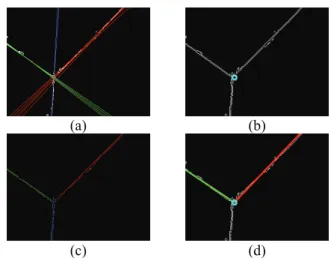
Multiple lines instead of just one are extracted by the Hough transform for each corner edge line, as shown in Fig. 3(c). To find single corner edge lines, we use a con- strained line refitting technique to refit a group of ex- tracted lines into a single one. The details are described as follows.
Step 1. Group lines whose Ηough transform parameters are close enough into three groups.
Step 2. Describe the lines in the form of u bv c+ + = 0 in the ICS.
Step 3. Compute the intersection points of the lines in the three groups.
Step 4. Compute the mean of the intersection points and denote it as Pcenter with coordinates (uc, vc) . Step 5. Collect edge line points in each group G into a
set S denoted by S = {(ui, vi), i = 1, 2, …, n}.
Step 6. Refit according to the least-square-error crite- rion the point data of S and Pcenter. into a new line L described by u + b'v + c' = 0 under the constraint that L passes Pcenter, resulting in fol- lowing formulas for b' and c':
b'= c
c
U u
V v
− −
− ; c'= −(uc+b v' )c with
1 n
i i
u
U =
∑
=nand 1
n
i i
v
V =
∑
=n.
An experimental result is shown in Fig. 4.
Proceedings of the 2006 International Conference on Intelligent Information Hiding and Multimedia Signal Processing (IIH-MSP'06) 0-7695-2745-0/06 $20.00 © 2006
Authorized licensed use limited to: National Chiao Tung University. Downloaded on March 13, 2009 at 22:29 from IEEE Xplore. Restrictions apply.
4. EXPERIMENTAL RESULTS
Our test bed is a small vehicle named Amigo Robot made by ActivMedia Robotics Technologies, Inc. In a navigation session, a user controls the vehicle to learn paths to create a navigation map. The vehicle starts navigation according to a path selected from the naviga- tion map. In most cases, the odometer information of the vehicle is accurate enough for short-distance guidance.
Whenever the vehicle arrives at a node where the vehicle has to conduct vehicle location by house corner detec- tion in the learning stage, it performs the required action to correct the vehicle location. An illustration of the learned node data, the navigation map, and an actual navigation path of one of our experiments is shown in Fig 5.
Fig 5. An illustration of learned data and navigation map.
5. CONCLUSIONS
A vehicle guidance method is proposed, by which the vehicle follows the nodes in a learned map to navigate in indoor environments. The information collected from the
odometer, including travel distances and turning angles of the vehicle, is used mainly for vehicle guidance through path nodes. House corners are used for vehicle location whenever existing to prevent mechanic error accumulation in the navigation session. Use of the house corner information has several merits which are not found in other approaches using other landmarks. The experimental results have revealed the feasibility of the proposed approach. Future research may be directed to the use of more complicated house corner shapes and other ceiling shape features.
5. REFERENCES
[1] G. N. DeSouza and A. C. Kak, “Vision for mobile robot navigation: a survey,” IEEE Trans. on Pattern Analysis and Machine Intelligence, vol. 24, no. 2, Feb. 2002, pp. 237-267.
[2] Y. C. Chen and W. H. Tsai, “Vision-based autono- mous vehicle navigation in complicated room envi- ronments with collision avoidance capability by simple learning and fuzzy guidance techniques,”
Proc. of 2004 Conf. on Computer Vision, Graphics
& Image Processing, Hualien, Taiwan, Aug. 2004.
[3] M. C. Chen and W. H. Tsai “Vision-based security patrolling in indoor environments using autono- mous vehicles,” Proc. of 2005 Conf. on Computer Vision, Graphics & Image Processing, Taipei, Tai- wan, Aug. 2005.
[4] I. Fukui, “TV image processing to determine the position of a robot vehicle,” Pattern Recognition, vol. 14, 1981, pp. 101-109.
[5] M. J. Magee and J. K. Aggarwal, “Determining the position of a robot using a single calibration ob- ject,” Proc. of IEEE Conf. on Robotics, Atlanta, Georgia, May, 1984, pp. 57-62.
[6] H. L. Chou and W. H. Tsai “A new approach to robot location by house corners,” Pattern Recogni- tion, vol. 19, 1986, pp. 439-451.
[7] J. W. Courtney and J. K. Aggarwal, “Robot guid- ance using computer vision,” Pattern Recognition, vol. 17, no 5, 1984, pp. 585-592.
[8] C. H. Ku and W. H. Tsai, “Obstacle avoidance in person following for vision-based autonomous land vehicle guidance using vehicle location estimation and quadratic pattern classifier,” IEEE Trans. on Industrial Electronics, vol. 48, no. 1, 2001, pp. 205- 215.
[9] Y. C. Chen and W. H. Tsai, “Vision-based autono- mous vehicle navigation in complicated room envi- ronments with collision avoidance capability by simple learning and fuzzy guidance techniques,”
Proc. of 2004 Conf. on Computer Vision, Graphics
& Image Processing, Hualien, Taiwan, Aug. 2004.
[10] C. C. Lai and W. H. Tsai, “Estimation of moving vehicle locations using wheel shape information in single 2-D lateral vehicle images by 3-D computer vision techniques,” Robotics and Computer Inte- grated Manufacturing, vol. 15, 1999, pp. 111-120.
(a) (b)
(c) (d) Fig 4 An experimental result of refitting house corner
edge lines. (a) Each set of lines represents an identical corner edge. (b) Computed corner center point. (c) The edge points (d) Refitting result of two corner edge lines.
Proceedings of the 2006 International Conference on Intelligent Information Hiding and Multimedia Signal Processing (IIH-MSP'06) 0-7695-2745-0/06 $20.00 © 2006
Authorized licensed use limited to: National Chiao Tung University. Downloaded on March 13, 2009 at 22:29 from IEEE Xplore. Restrictions apply.