Type A1SJHCPU-S8
Mitsubishi Programmable Controller
User's Manual
(Hardware)
Thank you for purchasing the Mitsubishi programmable controller MELSEC-A series.
Prior to use, please read both this manual and detailed manual thoroughly and familiarize yourself with the product.
MODEL A1SJHCPU-S8-U(H/W)-E MODEL
z SAFETY PRECAUTIONS z
(Read these precautions before using.)
When using Mitsubishi equipment, thoroughly read this manual and the associated manuals introduced in this manual.
Also pay careful attention to safety and handle the module properly.
These z SAFETY PRECAUTIONS z classify the safety precautions into two categories: "DANGER" and "CAUTION".
Procedures which may lead to a dangerous condition and cause death or serious injury if not carried out properly.
Procedures which may lead to a dangerous condition and cause superficial to medium injury, or physical damage only, if not carried out properly.
Depending on circumstances, procedures indicated by CAUTION may also be linked to serious results.
In any case, it is important to follow the directions for usage.
Store this manual in a safe place so that you can take it out and read it whenever necessary. Always forward it to the end user.
[DESIGN PRECAUTIONS]
DANGER
Install a safety circuit external to the PLC that keeps the entire system safe even when there are problems with the external power supply or the PLC module. Otherwise, trouble could result from erroneous output or erroneous operation.
(1) Outside the PLC, construct mechanical damage preventing interlock circuits such as emergency stop, protective circuits, positioning upper and lower limits switches and interlocking forward/reverse operations.
CAUTION DANGER
[DESIGN PRECAUTIONS]
DANGER
(2) When the PLC detects the following problems, it will stop calculation and turn off all output in the case of (a). In the case of (b), it will stop calculation and hold or turn off all output according to the parameter setting.
Note that the AnS series module will turn off the output in either of cases (a) and (b).
(a) The power supply module has over current
protection equipment and over voltage protection equipment.
(b) The PLC CPUs self-diagnosis functions, such as the watch dog timer error, detect problems.
In addition, all output will be turned on when there are problems that the PLC CPU cannot detect, such as in the I/O controller.
Build a fail safe circuit exterior to the PLC that will make sure the equipment operates safely at such times. See section 9.1 of this manual for example fail safe circuits.
(3) Output could be left on or off when there is trouble in the outputs module relay or transistor. So build an external monitoring circuit that will monitor any single outputs that could cause serious trouble.
When overcurrent which exceeds the rating or caused by short-circuited load flows in the output module for a long time, it may cause smoke or fire. To prevent this, configure an external safety circuit, such as fuse.
Build a circuit that turns on the external power supply when the PLC main module power is turned on. If the external power supply is turned on first, it could result in erroneous output or erroneous operation.
When a data link results in a communication error, the faulty station changes in operating status depending on the used data link type.
(1) For the data link data, the data prior to the communication error will be held.
(2) The MELSECNET (II,/B,/10) remote I/O station will turn all output off.
(3) The MELSECNET/MINI-S3 remote I/O station will hold the output or turn all output off depending on the E.C. remote setting.
Refer to the data link manuals regarding the method for setting the communication problem station and the operation status when there are communication problem.
[DESIGN PRECAUTIONS]
DANGER
When connecting a peripheral device to the CPU module or connecting a personal computer or the like to the intelligent function module to exercise control (data change) on the running PLC, configure up an interlock circuit in the sequence program to ensure that the whole system will always operate safely.
Also before exercising other control (program change, operating status change (status control)) on the running PLC, read the manual carefully and fully confirm safety.
Especially for the above control on the remote PLC from an external device, an immediate action may not be taken for PLC trouble due to a data communication fault.
In addition to configuring up the interlock circuit in the sequence program, corrective and other actions to be taken as a system for the occurrence of a data communication fault should be predetermined between the external device and PLC CPU.
When configuring a system, do not leave any slots vacant on the base.
Should there be any vacant slots, always use a blank cover (A1SG60) or dummy module (A1SG62).
When the extension base A1S52B, A1S55B or A1S58B is used, attach the dustproof cover supplied with the product to the module installed in slot 0.
If the cover is not attached, the module's internal parts may be dispersed when a short-circuit test is performed or
overcurrent/overvoltage is accidentally applied to the external I/O area.
CAUTION
Do not bunch the control wires or communication cables with the main circuit or power wires, or install them close to each other. They should be installed 100 mm (3.94 inch) or more from each other. Not doing so could result in noise that would cause erroneous operation.
[INSTALLATION PRECAUTIONS]
CAUTION
Use the PLC in an environment that meets the general specifications contained in this manual. Using this PLC in an environment outside the range of the general specifications could result in electric shock, fire, erroneous operation, and damage to or deterioration of the product.
Hold down the module loading lever at the module bottom, and securely insert the module fixing latch into the fixing hole in the base unit.
Incorrect loading of the module can cause a malfunction, failure or drop.
When using the PLC in the environment of much vibration, tighten the module with a screw.
Tighten the screw in the specified torque range. Undertightening can cause a drop, short circuit or malfunction. Overtightening can cause a drop, short circuit or malfunction due to damage to the screw or module.
When installing extension cables, be sure that the connectors of base unit are installed correctly. After installation, check them for looseness.
Poor connections could cause an input or output failure.
Correctly connect the memory cassette installation connector to the memory cassette. After installation, be sure that the connection is not loose. A poor connection could cause an operation failure.
Completely turn off the external power supply before loading or unloading the module. Not doing so could result in electric shock or damage to the product.
Do not directly touch the module's conductive parts or electronic components. Touching the conductive parts could cause an operation failure or give damage to the module.
[WIRING PRECAUTIONS]
DANGER
Completely turn off the external power supply when installing or placing wiring. Not completely turning off all power could result in electric shock or damage to the product.
When turning on the power supply or operating the module after installation or wiring work, be sure that the module's terminal covers are correctly attached. Not attaching the terminal cover could result in electric shock.
CAUTION
Be sure to ground the FG terminals and LG terminals to the protective ground conductor. Not doing so could result in electric shock or erroneous operation.
When wiring in the PLC, be sure that it is done correctly by checking the product's rated voltage and the terminal layout. Connecting a power supply that is different from the rating or incorrectly wiring the product could result in fire or damage.
Do not connect multiple power supply modules in parallel. Doing so could cause overheating, fire or damage to the power supply module.
External connections shall be crimped or pressure welded with the specified tools, or correctly soldered. Imperfect connections could result in short circuit, fires, or erroneous operation.
Tighten the terminal screws with the specified torque. If the terminal screws are loose, it could result in short circuits, fire, or erroneous operation. Tightening the terminal screws too far may cause damages to the screws and/or the module, resulting in fallout, short circuits, or malfunction.
Be sure there are no foreign substances such as sawdust or wiring debris inside the module. Such debris could cause fires, damage, or
[STARTUP AND MAINTENANCE PRECAUTIONS]
DANGER Do not touch the terminals while power is on.
Doing so could cause shock or erroneous operation.
Correctly connect the battery.
Also, do not charge, disassemble, heat, place in fire, short circuit, or solder the battery. Mishandling of battery can cause overheating or cracks which could result in injury and fires.
Switch all phases of the external power supply off when cleaning the module or retightening the terminal or module mounting screws. Not doing so could result in electric shock.
Undertightening of terminal screws can cause a short circuit or malfunction. Overtightening of screws can cause damages to the screws and/or the module, resulting in fallout, short circuits, or malfunction.
CAUTION
The online operations conducted for the CPU module being operated, connecting the peripheral device (especially, when changing data or operation status), shall be conducted after the manual has been carefully read and a sufficient check of safety has been conducted.
Operation mistakes could cause damage or problems with of the module.
Do not disassemble or modify the modules.
Doing so could cause trouble, erroneous operation, injury, or fire.
Use any radio communication device such as a cellular phone or a PHS phone more than 25cm (9.85 inch) away from the PLC.
Not doing so can cause a malfunction.
Switch all phases of the external power supply off before mounting or removing the module. If you do not switch off the external power supply, it will cause failure or malfunction of the module.
Do not drop or give an impact to the battery installed in the module.
Otherwise the battery will be broken, possibly causing internal leakage of electrolyte. Do not use but dispose of the battery if it has fallen or an impact is given to it.
[STARTUP AND MAINTENANCE PRECAUTIONS]
CAUTION
Always make sure to touch the grounded metal to discharge the electricity charged in the electricity charged in the body, etc., before touching the module.
Failure to do say cause a failure or malfunctions of the module.
[DISPOSAL PRECAUTIONS]
CAUTION
z When disposing of this product, treat it as industrial waste.
When disposing of batteries, separate them from other wastes ccording to the local regulations.
(For details of the battery directive in EU member states, refer to the QCPU User’s Manual (Type A1SJH(S8)/A1SH/A2SHCPU (S1) User's Manual).)
[TRANSPORTATION PRECAUTIONS]
CAUTION
z When transporting lithium batteries, make sure to treat them based on the transport regulations. (Refer to Appendix 2 for details of the
controlled models.)
REVISIONS
*The manual number is given on the bottom right of the front cover.
Print Date *Manual Number Revision
Nov., 1998 IB(NA) 66884-A First edition
Aug., 2003 IB(NA) 66884-B Partial corrections
SAFETY PRECAUTIONS, Section 1.1.1 Addition
Appendix 2
Dec., 2003 IB(NA) 66884-C Addition corrections A1SY42P
Partial corrections
Section 5.1.1, 5.2.1, 5.2.2, 5.3.1 Oct., 2008 IB(NA) 66884-D Partial corrections
SAFETY PRECAUTIONS, Section 1.1
This manual confers no industrial property rights or any rights of any other kind, nor does it confer any patent licenses. Mitsubishi Electric Corporation cannot be held responsible for any problems involving industrial property rights which may occur as a result of using the contents noted in this manual.
© 1998 Mitsubishi Electric Corporation
CONTENTS
1.SPECIFICATIONS ...1
1.1 SPECIFICATIONS...1
2.PERFORMANCE SPECIFICATIONS...2
2.1 Performance Specifications ...2
3.EMC DIRECTIVE AND LOW-VOLTAGE INSTRUCTION...3
3.1 Requirements for Compliance to EMC Directive (89/336/EEC)...3
3.1.1 EMC standards...3
3.1.2 Installation instructions for EMC...4
3.1.2.1 Control cabinet ...4
3.1.2.2 Connection of power and ground wires...5
3.1.2.3 Cables...6
3.1.2.4 Shield earthing...6
3.1.2.5 MELSECNET/II module...7
3.1.2.6 Ethernet module...8
3.1.2.7 Positioning Modules...8
3.1.2.8 I/O and other communication cables...9
3.1.2.9 Power supply module... 10
3.1.2.10 Ferrite core ... 10
3.1.2.11 Noise filter (power supply line filter)... 11
3.2 Requirements for conpliance with the Low Voltage Directive (73/23/EEC) and (93/68/EEC) ... 12
3.2.1 Standard applied for MELSEC-AnS... 12
3.2.2 Precautions when using the MELSEC-AnS series PC ... 12
3.2.3 Power supply... 13
3.2.4 Control cabinet... 14
3.2.5 Module installation ... 15
3.2.6 Grounding... 15
3.2.7 External wiring... 15
4.LOADING AND INSTALLATION... 16
4.1 Module Handling ... 16
4.2 Base Mounting ... 16
4.3 Fail-Safe Constructions... 19
4.3.1 General Safety Requirements... 19
4.3.2 Fail-Safe Circuitry Against to Failure of the PC... 20
4.4 Wiring... 22
4.4.1 Performance specifications for the A1SJHCPU-S8 built-in power supply... 22
4.4.2 Wiring instructions... 23
4.4.3 Wiring to module terminals ... 26
4.5 Precaution when Connecting the Uninterruptive Power Supply (UPS)... 27
5.2.1 Output module specifications...38
5.2.2 Output module connections ...40
5.3 Input/output combined modules...46
5.3.1 Input/output combined module specifications...46
5.3.2 Input/output composite module connections...48
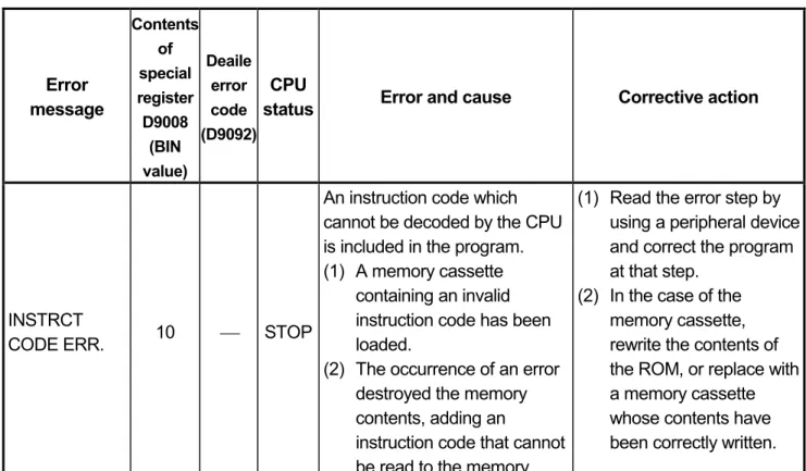
6.ERROR CODES ...51
6.1 Error Code List ...51
6.1.1 Error codes...51
APPENDICES ...61
Appendix 1 CPU-by-CPU Startup Names...61
Appendix 2 Transportation Precautions...61
Appendix 2.1 Controlled Models...61
Appendix 2.2 Transport Guidelines...61
This manual describes EMC standards and Low-Voltage instructions the handling precautions, and error codes of: A1SJHCPU-S8 (abbreviated to CPU in this manual)
Manuals
The manuals related to A1SJHCPU-S8 are listed below.
Refer to the following manuals when necessary.
Detailed manuals
Manual Name Manual No.
(Model Code) type A1SJH/A1SH/A2SHCPU(S1) User’s manual
Provides information on the performance, specifications, handling, etc. of the A1SJHCPU/A1SHCPU/A2SHCPU(S1) and on the memory cassette specifications and handling.
(Optional)
IB-66779 (13JL22)
Related manuals
Manual Name Manual No.
(Model Code) ACPU Programming Manual (Fundamentals)
Describes programming methods necessary for creating programs, device names, parameters, program types, memory area configuration, and so on.
(Optional)
IB-66249 (13J740)
ACPU Programming Manual (Common Instructions) Describes how to use the sequence instruction, basic instructions, applied instructions and microcomputer programs.
(Optional)
IB-66250 (13J741)
AnSHCPU/AnACPU/AnUCPU Programming Manual (Dedicated Instructions)
Describes instructions that have been expanded for A1SJHCPU/A1SHCPU/A2SHCPU(S1).
(Optional)
IB-66251 (13J742)
AnS Module type I/O User’s Manual
Describes the specification of the compact building block type I/O module.
(Optional)
IB-66541 (13JE81)
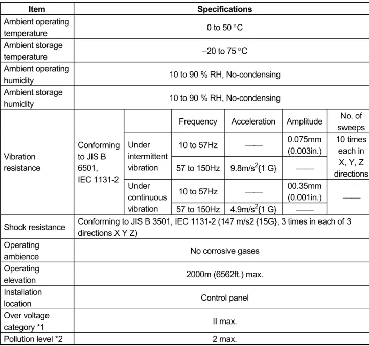
1. SPECIFICATIONS 1.1 SPECIFICATIONS
Table 1.1 General specification
Item Specifications
Ambient operating
temperature 0 to 50 °C
Ambient storage
temperature −20 to 75 °C
Ambient operating
humidity 10 to 90 % RH, No-condensing
Ambient storage
humidity 10 to 90 % RH, No-condensing
Frequency Acceleration Amplitude No. of sweeps 10 to 57Hz ⎯⎯ 0.075mm
(0.003in.) Under
intermittent
vibration 57 to 150Hz 9.8m/s2{1 G} ⎯⎯
10 times each in X, Y, Z directions 10 to 57Hz ⎯⎯ 00.35mm
(0.001in.) Vibration
resistance
Conforming to JIS B 6501, IEC 1131-2
Under continuous
vibration 57 to 150Hz 4.9m/s2{1 G} ⎯⎯
⎯⎯
Shock resistance Conforming to JIS B 3501, IEC 1131-2 (147 m/s2 {15G}, 3 times in each of 3 directions X Y Z)
Operating
ambience No corrosive gases
Operating
elevation 2000m (6562ft.) max.
Installation
location Control panel
Over voltage
category *1 II max.
Pollution level *2 2 max.
*1 : This indicates the section of the power supply to which the equipment is assumed to be connected between the public electrical power distribution network and the machinery within premises. Category II applies to equipment for which electrical power is supplied from fixed facilities. The surge voltage withstand level for up to the rated voltage of 300 V is 2500 V.
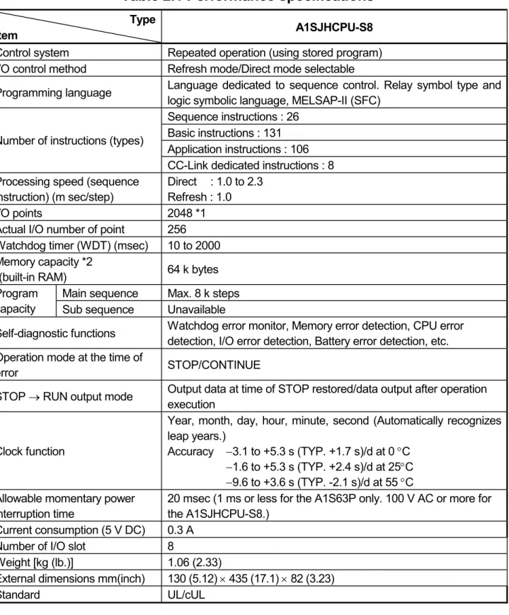
2. PERFORMANCE SPECIFICATIONS 2.1 Performance Specifications
The memory capacities of A1SJHCPU-S8 module, performances of devices, etc., are presented below.
Table 2.1 Performance specifications
Type
Item A1SJHCPU-S8
Control system Repeated operation (using stored program) I/O control method Refresh mode/Direct mode selectable
Programming language Language dedicated to sequence control. Relay symbol type and logic symbolic language, MELSAP-II (SFC)
Sequence instructions : 26 Basic instructions : 131 Application instructions : 106 Number of instructions (types)
CC-Link dedicated instructions : 8 Processing speed (sequence
instruction) (m sec/step)
Direct : 1.0 to 2.3 Refresh : 1.0
I/O points 2048 *1
Actual I/O number of point 256 Watchdog timer (WDT) (msec) 10 to 2000 Memory capacity *2
(built-in RAM) 64 k bytes Main sequence Max. 8 k steps Program
capacity Sub sequence Unavailable
Self-diagnostic functions Watchdog error monitor, Memory error detection, CPU error detection, I/O error detection, Battery error detection, etc.
Operation mode at the time of
error STOP/CONTINUE
STOP → RUN output mode Output data at time of STOP restored/data output after operation execution
Clock function
Year, month, day, hour, minute, second (Automatically recognizes leap years.)
Accuracy −3.1 to +5.3 s (TYP. +1.7 s)/d at 0 °C
−1.6 to +5.3 s (TYP. +2.4 s)/d at 25°C
−9.6 to +3.6 s (TYP. -2.1 s)/d at 55 °C Allowable momentary power
interruption time
20 msec (1 ms or less for the A1S63P only. 100 V AC or more for the A1SJHCPU-S8.)
Current consumption (5 V DC) 0.3 A Number of I/O slot 8
Weight [kg (lb.)] 1.06 (2.33)
External dimensions mm(inch) 130 (5.12) × 435 (17.1) × 82 (3.23) Standard UL/cUL
*1 The I/O device after the actual input points can be used as MELSECNET(/B), MELSECNET/MINI, or CC-Link.
*2 The maximum total memory that can be used for parameters, T/C set values, program capacity, file registers, number of comments, sampling trace, and status latch is 32 k/64 k bytes. The memory capacity is fixed. No expansion memory is available.
3. EMC DIRECTIVE AND LOW-VOLTAGE INSTRUCTION
3.1 Requirements for Compliance to EMC Directive (89/336/EEC)
The EMC Directive (89/336/EEC) become mandatory within Europe from January 1st 1996. The EMC directive in essence defines the amount of electromagnetic output a product is allowed to produce and how susceptible that product is to electromagnetic interference. Any manufacturer or importer of electrical/electronic apparatus must before releasing or selling products within Europe after that date have a CE mark attached to their goods. Testing to comply with the directive is done by use of agreed European standards which define limits for radiated and mains conducted electromagnetic emissions from equipment, levels of immunity to radiated emissions, ability for equipment to cope with transient voltage surges and electro-static discharges.
When installed in the specified manner this unit will be compliant with the relevant standards EN50081-2 and prEN50082-2 as applicable in the EMC directive.
Failure to comply with these instructions could lead to impaired EMC performance of the equipment and as such Mitsubishi Electric Corporation can accept no liability for such actions.
3.1.1 EMC standards
When the PC is installed following the directions given in this manual its EMC performance is compliant to the following standards and levels as required by the EMC directive.
Specifications Test Item Test Description Standard Values
EN55011 Radiated noise
Measure the emission released by the product.
30M-230MHz QP : 30dBm V/m (30m
measurement) *1 230M-1000MHz QP : 37dBm V/m (30 m
measurement) EN50081-2:
1995
EN55011
Conduction noise
Measure the emission released by the product to the power line.
150K-500kHzQP:
79dB, Mean : 66dB *1 500K-30MHz QP : 73dB, Mean: 60dB IEC801-2
Static electricity immunity *2
Immunity test by applying static electricity to the module
enclosure.
4kV contact discharge 8kV air discharge IEC801-3
Radiated electromagnetic field *2
Immunity test by applying aradiated electric field to the product.
10V/m, 27-500MHz prEN50082-2:
1991
Immunity test by applying burst
Specifications Test Item Test Description Standard Values EN61000-4-2
Static electricity immunity *2
Immunity test by applying static electricity to the module
enclosure.
4kV contact discharge 8kV air discharge EN61000-4-4
First transient burst noise
Immunity test by applying burst noise to the power line and signal cable., 2kV
2kV ENV50140
Radiated electromagnetic field AM modulation *2
Immunity test by applying aradiated electric field to the product.
10V/m, 80-1000M Hz, 80% AM modulation @ 1kHz
ENV50204
Radiated electromagnetic field
Pulse modulation *2
Immunity test by applying aradiated electric field to the product.
10V/m, 900MHz, 200Hz pulse modulation, 50%
duty EN50082-2:
1995
ENV50141 Conduction noise
Immunity test by inducting an electromagnetic field in the power line signal cable.
10Vrms, 0.15-80 Hz, 80% modulation
@1kHz (*1) QP: Quasi-peak value, Mean : Average value
(*2) The PC is an open type device (device installed to another device) and must be installed in a conductive control pauel or cabinet.
The tests for the corresponding items were performed while the PC was installed to inside the control pauel or cabinet.
3.1.2 Installation instructions for EMC 3.1.2.1 Control cabinet
When constructing a control cabinet where the PC system will be installed, the following instructions must be followed.
(1) Use a conductive control cabinet.
(2) When attaching the control cabinet's top plate or base plate, mask painting and weld so that good surface contact can be made between the cabinet and plate.
(3) To ensure good electrical contact with the control cabinet, mask the paint on the installation bolts of the inner plate in the control cabinet so that contact between surfaces can be ensured over the widest possible area.
(4) Earth the control cabinet with a thick wire so that a low impedance connection to ground can be ensured even at high frequencies. (22mm2 wire or thicker is recommended.)
(5) Holes made in the control cabinet must be 10cm (3.94in.) diameter or less.
If the holes are 10cm (3.94in.) or larger, radio frequency noise may be emitted.
(6) Connect the door of cabinet to the main body with flat braided wires at as many points as possible so that a low impedance can be ensured even at high frequencies.
3.1.2.2 Connection of power and ground wires
Ground and power supply wires for the PC system must be connected as described below.
(1) Provide an earthing point near the power supply module. Earth the power supply's LG and FG terminals (LG : Line Ground, FG : Frame Ground) with the thickest and shortest wire possible. (The wire length must be 30cm (11.18in.) or shorter.) The LG and FG terminals function is to pass the noise generated in the PC system to the ground, so an impedance that is as low as possible must be ensured. As the wires are used to relieve the noise, the wire itself carries a large noise content and thus short wiring means that the wire is prevented from acting as an antenna.
Note) A long conductor will become a more efficient antenna at high frequency.
(2) The earth wire led from the earthing point must be twisted with the power supply wires. By twisting with the earthing wire, noise flowing from the power supply wires can be relieved to the earthing. However, if a filter is installed on the power supply wires, the wires and the earthing wire may not need to be twisted.
(3) Except for A1S61PN and A1S62PN, short between FG and LG terminals by a short jumper wire.
3.1.2.3 Cables
The cables led from the control cabinet contain a high frequency noise element and outside the control panel these cables act as antennae and radiate noise.
The cables connected to input/output modules or special modules which leave the control panel should always be shielded cables.
Mounting of a ferrite core on the cables is not required (excluding some models) but if a ferrite core is mounted, the noise radiated through the cable can be suppressed further.
Use of a shielded cable is also effective for increasing the noise immunity level.
The PC system's input/output and special function module provide a noise immunity level of equivalent to that stated in IEC801-4 : 2kV when a shielded cable is used. If a shielded cable is not used or if the shield earthing treatment is not suitable even when used (See Section 3.1.2.4), the noise immunity level is less than 2kV.
Note) prEN50082-2 specifies the noise resistance level based on the signal wire application.
Signals involved in process control : 2kV Signals not involved in process control : 1kV
The meaning of "involved in process control" is not defined in prEN50082-2.
However, when the purposes of the EMC Directive are considered, the signals that could cause personal injury or risks in the facility if a malfunction occurs should be defined as "signals involved in process control". Thus, it is assumed that a high noise immunity level is required.
3.1.2.4 Shield earthing
When the shield of the shielded cable is earthed to the cabinet body, please ensure that the shield contact with the body is over a large surface area. If the cabinet body is painted it will be necessary to remove paint from the contact area.
All fastenings must be metallic and the shield and earthing contact must be made over the largest available surface area. If the contact surfaces are too uneven for optimal contact to be made either use washers to correct for surface inconsistencies or use an abrasive to level the surfaces. The following diagrams show examples of how to provide good surface contact of shield earthing by use of a cable clamp.
Shield section
Screw
Shielded cable Paint mask
Clamp fitting
(a) Peel the cable insulation off and expose the
shield section.
(b) Sandwich the exposed shield section with the and earth to the control cabinet over a wide area.
Note) The method of earthing by soldering a wire onto the shield section of the shielded cable as shown below is not recommended. The high frequency impedance will increase and the shield will be ineffective.
Shielded cable Wire
Crimp terminal
3.1.2.5 MELSECNET/II module
The following requirements apply to A1SJ71AR21, A1SJ71BR11, AnNCPUR21, AnACPUR21.
(1) Always use a triaxial cable for the module. The radiated noise in the band of 30MHz or higher can be suppressed by using a triax cable. Earth the outer shield by the method described in Section 3.1.2.4.
Earth this section
(2) Always mount a ferrite core onto the triaxial cable. Mount the ferrite core near the control cabinet outlet of each cable. Use of the TDK ZCAT3035 ferrite core is recommended.
3.1.2.6 Ethernet module
(1) Always earth the AUI cable connected to the A1SJ71E71-B5. The AUI is a shielded cable so remove the outer insulation and connect to earth the exposed shield section using as wide a surface area as possible in the manner shown below.
Shield AUI cable
(2) Always use a triaxial cable for the coaxial cable connected to the A1SJ71E71-B2. The earthing precautions are the same as Section 3.1.2.5.
(3) For A1SJ71E71-B2/B5, always mount a ferrite core in addition to items (1) and (2) above. Use of the TDK ZCAT3035 ferrite core is recommended.
3.1.2.7 Positioning Modules
(1) When wiring with a 2m (6.6ft.) or less cable
Ground the shield section of the external wiring cable with the cable clamp.
(Ground the shield at the closest location to the A1SD75 external wiring connector.)
Wire the external wiring cable to the drive unit and external device with the shortest distance.
Install the drive unit in the same panel.
Power supply module CPU module A1SD75 module
Drive unit External wiring connector
External wiring cable (within 2 m (6.56 ft.)) Cable clamp
(2) When wiring with cable that exceeds 2m (6.6ft.), but is 10m (32.8ft.) or less Ground the shield section of the external wiring cable with the cable clamp.
(Ground the shield at the closest location to the AISD75 external wiring connector.)
Install a ferrite core.
Wire the external wiring cable to the drive unit and external device with the shortest distance.
Power supply module CPU module A1SD75 module
Drive unit External wiring connector
Ferrite core
External wiring cable (2 m to 10 m (6.56 ft. to 32.81 ft.)) Cable clamp
(3) Ferrite core and cable clamp types and required quantities
(a) Cable clamp
Type : AD75CK (Mitsubishi Electric) (b) Ferrite core
Type : ZCAT3035-1330 (TDK ferrite core) (c) Required quantity
Required Qty Cable length Prepared part
1 axis 2 axes 3 axes
Within 2m (6.6 t.) AD75CK 1 1 1
AD75CK 1 1 1
2m (6.6ft.) to 10m (32.8ft.)
ZCAT3035-1330 1 2 3
3.1.2.8 I/O and other communication cables
Always earth the shield section of the I/O signal cables and other communication cables (RS-232-C, RS-422, etc.) in the same manner as described in Section 3.1.2.4 if the cables go outside of the control cabinet.
3.1.2.9 Power supply module
The precautions required for each power supply module are described below.
Always observe the items noted as precautions.
Model Precautions A1S61P
A1S62P A1S63P *1
Always mount one of the filters listed in Section 3.1.2.10 to the incoming power supply lines.
A1S61PEU
A1S62PEU None A1S61PN
A1S62PN Make sure to short and ground the LG and FG terminals.*2 A1SJCPU-S3
A1SJHCPU A1SJHCPU-S8
Always ground the LG and FG terminals after short-circuiting them.
*1 If a sufficient filter circuitry is built into a 24VDC external power supply module, the noise generated by A1S63P will be absorbed by that filter circuit, so a line filter may not be required.
Filtering circuitry of version F or later of A1S63P is improved so that a external line filter is not required.
*2 To ensure the compliance with CE (EN6111-21/A11), make sure to short the LG and FG terminals using a wire of 6 to 7cm.
3.1.2.10 Ferrite core
A ferrite core is effective for reducing noise in the band of 30MHz to 100MHz.
Mounting of a ferrite core is not necessary except for some particular models described in Section 3.1.2.5 and 3.1.2.6. However if further attenution of noise is necessary, mounting of a ferrite core on cables which radiate noise is recommended. When a ferrite core is mounted, mount the ferrite core just before the point where the cable goes outside of the cabinet. The ferrite will not be effective if the mounting position is not adequate.
Ferrite
core Ferrite
core
Noise Noise
(a) When there is a distance from the cable exit hole, the noise will jump over the ferrite, thus the effect will be halved.
(b) When mounted by the cable exit hole, the noise will not jump over the ferrite.
3.1.2.11 Noise filter (power supply line filter)
The noise filter (power supply line filter) is a device effective to reduce conducted noise. Except for some particular models described in Section 3.1.2.8, installation of a noise filter onto the power supply lines is not necessary. However conducted noise can be reduced if it is installed. (The noise filter is generally effective for reducing conducted noise in the band of 10MHz or less.) Usage of the following filters is recommended.
Model name FN343-3/01 FN660-6/06 ZHC2203-11
Manufacturer SCHAFFNER SCHAFFNER TDK
Rated current 3A 6A 3A
Rated voltage 250V
The precautions required when installing a noise filter are described below.
(1) Do not bundle the wires on the input side and output side of the noise filter. When bundled, the output side noise will be induced into the input side wires from which the noise was filtered.
Filter
Induction
Output side (device side) Input side
(power supply side)
Filter
Output side (device side) Input side
(power supply side)
(a) The noise will be included when the input and output wires are bundled.
(b) Separate and lay the input and output wires.
(2) Earth the noise filter earthing terminal to the control cabinet with the shortest wire possible (approx. 10cm (3.94 in.)).
3.2 Requirements for conpliance with the Low Voltage Directive (73/23/EEC) and (93/68/EEC)
The Low Voltage Directive is mandatory within Europe, effective 1st January 1997.
The Low Voltage Directive requires each device which operates with power supply ranging from 50VAC to 1000V and 75VDC to 1500V to satisfy necessary safety items.
In the Sections from 3.2.1 to 3.2.8, cautions on installation and wiring of the MELSEC-AnS series PC to conform to the Low Voltage Directive requires are described.
We have put the maximum effort to develop this material based on the requirements and standards of the Directive that we have collected. However, compatibility of the devices which are fabricated according to the contents of this manual to the above Directive is not guaranteed. Each manufacturer who fabricates such device should make the final judgement about the application method of the Low Voltage Directive and the product compatibility.
3.2.1 Standard applied for MELSEC-AnS
The standard applied for MELSEC-AnS is EN61010-1 safety of devices used in measurement rooms, control rooms, or laboratories.
For the modules which operate with the rated voltage of 50VAC/75VDC or above, we have developed new models that conform to the above standard.
For the modules which operate with the rated voltage under 50VAC/75VDC, the conventional models can be used, because they are out of the the Low Voltage Directive application range.
3.2.2 Precautions when using the MELSEC-AnS series PC
Module selection
(1) Power module
For a power module with rated input voltage of 100/200VAC, select a model in which the internal part between the first order and second order is intensively insulated, because it generates hazardous voltage (voltage of 42.4V or more at the peak) area.
For a power module with 24VDC rated input, a conventional model can be used.
(2) I/O module
For I/O module with rated input voltage of 100/200VAC, select a model in which the internal area between the first order and second order is intensively insulated, because it has hazardous voltage area.
For I/O module with 24VDC rated input, a conventional model can be used.
(3) CPU module, memory cassette, base unit
Conventional models can be used for these modules, because they only have a 5VDC circuit inside.
(4) Special module
Conventional models can be used for the special modules including analog module, network module, and positioning module, because the rated voltage is 24VDC or less.
(5) Display device
Use an A870GOT CE compatible model.
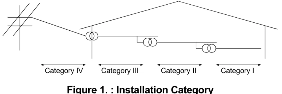
3.2.3 Power supply
The insulation specification of the power module was designed assuming installation category II. Be sure to use the installation category II power supply to the PC.
The installation category indicates the durability level against surge voltage generated by lightning strike. Category I has the lowest durability; category IV has the highest durability.
Category III Category II Category I Category IV
Figure 1. : Installation Category
3.2.4 Control cabinet
Because the PC is open type equipment (a device designed to be stored within another module), be sure to use it only when installed in a control cabinet.
(1) Electrical shock prevention
In order to such as the operators from electric shocks, the control box must have the following functions :
(a) The control cabinet must be equipped with a lock so that only skilled or qualified personnel.
(b) The control cabinet must be fitted with advice which automatically stops the power supply when the cabinet is opened.
(2) Dustproof and waterproof features
The control cabinet also provides protection from dust, water and ether substances. Insufficient ingression protection may lower the insulation withstand voltage, resulting in insulation destruction. The insulation in our PC is designed to cope with the pollution level 2, so use in an environment with pollustion level 2 or better.
Pollution level 1 : An environment where the air is dry and conductive dust
does not exist.
Pollution level 2 : An environment where conductive dust does not usually exist, but occasional temporary conductivity occurs due to the accumulated dust.
Generally, this is the level for inside the control box equivalent to IP54 in a control room or on the floor of a typical factory.
Pollution level 3 : An environment where conductive dust exits and conductivity may be generated due to the accumulated dust.
An environment for a typical factory floor.
Pollution level 4 : Continuous conductivity may occur due to rain, snow, etc. An outdoor environment.
As shown above, the PC can realize the pollution level 2 when stored in a control cabinet equivalent to IP54.
3.2.5 Module installation
(1) Installing modules contiguously
In A series PCs, the left side of each I/O module is left open. When installing an I/O module to the base, do not make any open slots between any two modules. If there is an open slot on the left side of a module with 100/200VAC rating, the printed board which contains the hazardous voltage circuit becomes bare. When it is unavoidable to leave an open slot, be sure to install the blank module (A1SG60).
When using the A1S5 B expansion base with no power supply, attach the cover packaged with the expansion base to the side of the leftmost module.
3.2.6 Grounding
There are two kinds of grounding terminals as shown below. Both terminals must be grounded.
Be sure to ground the protective grounding for the safety reasons.
Protective grounding : Maintains the safety of the PC and improves the noise resistance.
Functional grounding : Improves the noise resistance.
3.2.7 External wiring
(1) 24VDC external power supply
For special modules that require a 24VDC I/O module or external power supply, select a model which complies with the Low Voltage Directive’s requirements for isolation between the primary and secondary circuits.
(2) External devices
When a device with a hazardous voltage circuit is externally connected to the PC, select a model which complies with the Low Voltage Directive’s requirements for isolation between the primary and secondary circuits.
(3) Insulation requirements
Dielectric withstand voltages are shown in Table 2.
4. LOADING AND INSTALLATION 4.1 Module Handling
(1) Module enclosure, terminal block connectors and pin connectors are made of resin; do not drop them or subject them to strong impact.
(2) Do not remove modules' printed circuit boards from the enclosure in order to avoid changes in operation.
(3) During wiring, take care to ensure that wiring off-cuts, etc. do not get inside the case. If anything does get inside the case, remove it.
(4) Tighten the module mounting and fixing screws as specified below.
Screw Tightening Torque N x cm (kgf x cm) [lb x inch]
Module mounting screws (M4) 78.4 to 117.6 (8 to 12) [45 to 67]
I/O module terminal screw (M3.5) 58.8 to 88.2 (6 to 9) [34 to 50]
Power supply module terminal screws
(M3.5) 58.8 to 88.2 (6 to 9) [34 to 50]
4.2 Base Mounting
(1) Mounting dimension
Mounting dimensions of each base unit are as follows:
CPU 0 1 2 3 4 5 6 7
POWER MITSUBISHI ELECTRIC CORPORATION BD626E680G52
MADE IN JAPAN E.S.D. A1S68B
Ws W
Hs H
Dimensions: mm (inch) A1S52B (S1) A1S55B (S1) A1S58B (S1) A1S65B (S1) A1S68B (S1) W 155 (6.10) 260 (10.24) 365 (14.37) 315 (12.40) 420 (16.54) Ws 135 (5.31) 240 (9.45) 345 (13.58) 295 (11.61) 400 (15.75)
H 130 (5.12)
Hs 110 (4.33)
(2) Base unit mounting position
Provide a clearance between the top and bottom of modules and wall of structure or components as given below. This is required for ventilation and allows easy replacement of modules.
Main base, Extension base 30mm (1.18inch) or over (CPUA1S5[ ]B (S1),A1S6[ ]B (S1))
Extension base
(A5[ ]B, A6[ ]B) 80mm (3.15inch) or over
Main base 30mm (1.18inch) or over
Conduit
(50mm (1.97inch) or less in height)
30mm (1.18inch) or over 30mm (1.18inch) or over
30mm (1.18inch) or over Extension base
(A1S5[ ]B(S1), A1S6[ ]B(S1))
Main base 30mm (1.18inch) or over
30mm (1.18inch) or over 80mm (3.15inch) or over
80mm (3.15inch) or over
Extension base (A1S5[ ]B,A1S6[ ]B)
Conduit
(50mm (1.97inch) or less in height)
(3) Unit mounting orientation
(a) Since the PC generates heat, it should be mounted on a well ventilated location in the orientation shown below.
(b) Do not mount it in either of the orientations shown below.
(4) Mount base unit on a flat surface. If the mounting surface is not even, this may strain the printed circuit boards and cause malfunctions.
(5) Avoid mounting base unit in proximity to vibration sources such as large magnetic contractors and no-fuse circuit breakers; mount these on a separate panel or at a distance.
(6) In order to avoid the effects of radiated noise and heat, provide the clearances indicated below between the PC and devices that generate noise or heat (contactors and relays).
Required clearance in front of: at least 100mm (3.94inches)
Required clearance on the right and left of : at least 50mm (1.97inches)
100mm (3.94inch)
or over Contactor, relay, etc.
50mm (1.97inch) or over
50mm (1.97inch) or over
(7) If you want to mount base units on a DIN rail, please note the following points.
(a) Suitable DIN rail types (JIS-C2B12) are listed as follows:
TH35-7.5Fe TH35-7.5Al TH35-15Fe
*JIS: Japanese Industrial Standard
(b) Spacing intervals for DIN rail mounting screws
When using a TH35-7.5Fe or TH35-7.5Al DIN rail, rail mounting screws should be placed at a pitch of 200mm (7.87inch) or less in order to ensure that the rail has sufficient strength.
P P P
DIN rail DIN rail mounting screw
P=200 mm (7.87 inches) or less 35 mm
(1.38 inches)
(8) It is recommendable to fix the base module to the control panel directly using screws, as this method ensures higher resistance to vibration than when using a DIN rail.
4.3 Fail-Safe Constructions
4.3.1 General Safety Requirements
DANGER z Safety circuitry must be so designed and constructed externally that an entire system stays in safe in case of a external power supply failure and/or PC failure. In particular, the following safety circuitry are required to constructed outside of the PC.
(1) Emergency stop circuit, protection circuit, interlocking circuit for contrary operations such as forward and reverse movement, and hardware stroke limit circuit for positioning controls must be constructed externally.
(2) In case of hardware failure which PC CPU cannot detect occurs, all or some output signals could be turned on without program instructions. An external safety circuitry must be so constructed that safety of equipment or machine can be protected from such case. Please refer to Sub-clause 4.3.2 for details.
(3) In some cases, relays or transistors used in output modules stay always ON or OFF as failure symptoms. If such failure could cause serious damage on persons or properties, those safety critical output signals must be externally monitored.
z If the power to the PC is turned ON after turning ON the external power supply used for the process control with the DC output module, the DC output module may make an erroneous output for an instant. Take the following procedures for power up of the equipment, in order to prevent such erroneous input and output to/from the PC.
(1) Turn ON the power to the PC.
(2) Turn ON the external power supply used for the process control.
4.3.2 Fail-Safe Circuitry Against to Failure of the PC
Though Mitsubishi PCs are manufactured under strict quality control, they may cause failure or abnormal operations due to unspecific reasons. To prevent the abnormal operation of the whole system, machine breakdown, and accidents, fail-safe circuitry against to failure of the PC must be constructed outside the PC.
The following page gives an example of system designing that conforms to the explanation mentioned above and an example of fail-safe measures when the PC causes a failure.
(1) System design circuit example
POWER POWER
Power to output equipment switched OFF when the STOP signal is given.
Low battery alarm (Lamp or buzzer)
ON when run by M9039
Voltage relay is recommended
Set time for DC power supply to be established.
Low battery alarm (Lamp or buzzer)
Interlock circuits as necessary.
FUSE
TRANSFORMER
FUSE TRANSFORMER
ALL AC Mixed AC and DC
CPU M9006 CPU M9039
XM
M9006 M9039
XM TM TM N0 M10 PROGRAM
PROGRAM Ym
Yn Y1 M9084
Ym Yn TM M9084
START
MC STOP SW START SW
MC STOP
INPUT MODULE XM
INPUT MODULEXM OUTPUT MODULE
RA2
RA2 Ym
Yn
OUTPUT MODULE
MC
MC L
RA1
RA2 MC2 MC1
RUN/STOP circuit interlocked with RA1 (run monitor relay) Input switched when power supply establ- ished.
(−)(+)
MC1 MC2
MC1 MC2 MC1
MC2
Y1
Ym Yn OUTPUT MODULE
RA2
L
RA1
MC1 N0 M10
MC MC
RA1
RA1 MC MC
RA1 switched ON by M9039
(run monitor relay)
Power to output equipment switched OFF when the STOP signal is given.
Provide external interlock circuits for conflicting op- erations, such as forward rotation and reverse rota- ion, and for parts that co- uld damage the machine or cause accidents if no interlock were used.
TRANSFORMER FUSE
DCPOWER SUPPLY
FUSE
OUTPUT MODULE
In the case of an emerge- ncy stop or a stop caused by a limit switch.
In the case of an emergen- cy stop or a stop caused by a limit switch.
The power-ON procedure is an follows:
For AC
1) Switch CPU to RUN.
2) Set the ON the power.
3) Turn ON the start switch.
4) When the magnetic contactor (MC) comes in, the output equipment is powered and may be driven by the program.
For AC/DC
1) Switch CPU to RUN.
2) Set the ON the power.
3) Turn ON the start switch.
4) When DC power is established, RA2 goes ON.
5) Timer (TM) times out after the DC power reaches 100%.
(The TM set value should be the period of time from when RA2 goes ON to the establishment of 100% DC voltage. Set this value to approximately 0.5 seconds.) 6) When the magnetic contactor (MC) comes in, the
output equipment is powered and may be driven by the program.
(If a voltage relay is used at RA2, no timer (TM) is required in the program.)
(2) Failure of a CPU or memory can be detected by the self diagnosis function. However, Failure of I/O control area may not be detected by the CPU. In such cases, all I/O points turn ON or OFF depending on a condition of problem, and normal operating conditions and operating safety cannot sometimes be maintained. Examples of fail-safe circuitry are described as follows:
(a) Using on-delay and off-delay timers
Internal program M9032
T1 ON delay timer
1sec
T2 OFF delay timer
1sec L
L
MC T1 T2
+
−
DC24V Y00
Y01
Y0F 24V
0V Y00
Y00
External load
CPU module Output module *1
MC
sec0.5 0.5 sec
4.4 Wiring
4.4.1 Performance specifications for the A1SJHCPU-S8 built-in power supply Table 4.1 Performance specifications for
the A1SJHCPU-S8 built -in power supply
Type
Item A1SJHCPU-S8
100-120VAC ±10% 15%
(85 to 132VAC) 500-240VAC ±10% 15%
Input power supply
(170 to 264VAC)
Input frequency 50/60Hz ±3Hz
Input voltage distortion factor Within 5% (See Section 4.5.) Input maximum apparent power 100VA
Rush current 20A 8msec or less
Rated output 5 VDC 3A
Overcurrent protection *1 3.3A or over Overvoltage protection Not provided
Efficiency 65 % or over
Power supply indication POWER LED indicator Terminal screw size M3.5 × 8
Applicable solderless terminal 0.3 to 2 mm2
Applicable solderless terminal RAV 1.25-3.5, RAV 2-3.5
Allowable momentary power failure 20msec or less (100VAC or over)
POINT
*1 : Overcurrent protection
When a current larger than the specification value flows through the 5 V DC circuit, the overcurrent protection device cuts off the circuit and stops the system.
The POWER LED turns off or lights dimly due to the voltage drop. If this device operated, remove causes of failures such current capacity shortage and short-circuit and restart the system.
4.4.2 Wiring instructions
This section gives the wiring instruction for the system.
DANGER
z Before beginning any installation or wiring work, make sure all phase of the power supply have been obstructed from the outside. Failure to completely shut off the power supply phase may cause electric shock and/or damage to the module.
z When turning on the power or operating the module after installation or wiring work, be sure the module’s terminal covers are correctly
attached. Failure to attach the terminal covers may result in electric shock.
CAUTION
z Be sure to ground the FG terminals and LG terminals and LG terminals to the protective ground conductor.
Not doing so could result in electric shock or erroneous operation.
z When wiring the PC, check the rated voltage and terminal layout of the wiring, and make sure the wiring is done correctly. Connecting a power supply the differs from the rated voltage or wiring it incorrectly may coups fire or breakdowns.
z Tighten the terminal screws with the specified torque. If the terminal screw are loose, it may result in short circuits, fire or malfunction.
If the terminal screws are tightened too much, it may damage the screws and the module result in short circuits, malfunction or cause the module to fall out.
z Be careful not to let foreign matter such as filings or wire chips gear inside the module. These can cause fire, breakdowns and malfunction.
z Perform correct pressure-welding, crimp-contact or soldering for connectors for the outside using the specified tools. See the User’s Manual of the corresponding I/O module for tools required to perform pressure-welding and crimp-contact.
Incorrect connection may cause short circuits, fire, or malfunction.
Precautions when wiring power supply cable are described.
(1) Wiring power supply
(a) Separate the PC’s power supply line from the lines for I/O devices and power devices as shown below.
When there is much noise, connect an insulation transformer.
PC PC power
supply Main power
supply
I/O power supply
Main circuit device
I/O devices
Main circuit device Insulation
transformer AC200V
T1
(b) 100VAC, 200VAC and 24VDC wires should be twisted as dense as possible. Connect the modules with the shortest distance.
Also, to reduce the voltage drop to the minimum, use the thickest wires possible (maximum 2mm2).
(c) As a countermeasure to power surge due to lightening, connect a surge absorber for lightening as shown below.
AC
E1
E2
Surge absorber for lightening PC/IO
devices
(d) Do not supply 24VDC power supply from more than one power supply modules in parallel to one I/O module. If they are connected so, the power supply modules will become not and could be caused fire and/or malfunction.
I/O module
24VDC
24VDC
24VDC
External power supply
Power supply modulePower supply module Power supply module I/O module
POINTS
(1) Separate the ground of the surge absorber for lightening (E1) from that of the PC (E2).
(2) Select a surge absorber for lightening whose power supply voltage dose no exceed the maximum allowable circuit voltage even at the time of maximum power supply voltage elevation.
4.4.3 Wiring to module terminals
This section explains the wiring of power lines and grounding lines to the main and extension bases.
LG
A1SJHCPU-S8
100-120/200-240VAC INPUT
FG
Extension base unit (A1S68B) I/O
A1S61PN AC
Insulation Transformer
Fuse
AC100/
110V
ACDC
Connect to the 24VDC terminals of an I/O module that requires 24VDC internally.
Ground Grounding wire
AC100/110V Extension cable
INPUT 100-240VAC NC NC(FG)
(LG)
POINTS
(1) Use thick wires (MAX. 2mm2) as much as possible for the 100/200VAC and 24VDC power supply, and twist the wires beginning with the connecting terminal. When a solderless terminal is used, use a solderless terminal with an insulation sleeve to prevent short-circuit when the terminal screw becomes loose.
(2) When the LG and FG terminals are connected, they must be grounded.
If they are not grounded, the operation processing will be easily influences by noise. Use caution not to touch the LG terminal since it has an electric potential of half the input voltage.
(3) A1S61PN and A1S62PN do not need to be switched as the are 100-240 V AC wide-range.
4.5 Precaution when Connecting the Uninterruptive Power Supply (UPS)
Be sure of the following items when connecting the AnSHCPU system to the uninterruptive power supply (abbreviated as UPS hereafter):
Use the online UPS with a voltage distortion of 5% or less or line-interactive UPS.
For standby UPS, select the Mitsubishi FREQUPS-F series UPS (serial No. P or later) such as FW-F10-03K/0.5K.
Do not use the stand UPS other than above.