Performance Analysis of New Fault-Tolerant Flux- Mnemonic Doubly-Salient Permanent-Magnet Motor
Drive
Chuang Yu
Department of Electrical and Electronic Engineering The University of Hong Kong
Hong Kong, China [email protected]
Yu Gong
Department of Automation Shanghai University
Shanghai, China [email protected]
Abstract—Due to the flux-mnemonic nature of AlNiCo permanent magnets (PMs), the flux-mnemonic motor can offer efficient online air-gap flux control. By incorporating the flux- mnemonic concept into the hybrid-field doubly salient PM (DSPM) motor structure, the resulting flux-mnemonic DSPM motor can flexibly operate at the magnetizing mode when PMs are fully magnetized or the demagnetizing mode when PMs are fully demagnetized. The key of this paper is to artfully utilize these modes for fault-tolerant operation of the proposed flux- mnemonic DSPM motor drive. Namely, the motor drive works in a remedial magnetizing mode during open-circuit fault, and a remedial demagnetizing mode during short-circuit fault.
Comprehensive performance analysis is carried out to verify the validity of the proposed fault-tolerant flux-mnemonic DSPM motor drive.
Keywords—Doubly salient, Fault tolerance, Flux-mnemonic, Memory motor, Open-circuit, Short-circuit.
I. I NTRODUCTION
For some important applications such as electric vehicle propulsion, motor drives need to provide reasonable performance even under fault [1-5]. Actually, limp-home operation is highly desirable for modern electric vehicles. So, it is important to design motor drives with the capability of fault tolerance [6,7], which means that they should continue to operate in a satisfactory manner under fault conditions. The incorporation of fault tolerance into a motor drive involves fault detection technique as well as the fault remediation [8].
This paper will focus on the investigation of fault remediation while assuming that the fault detection is already in place.
It is well known that the switched reluctance (SR) motor inherently possesses high fault tolerance due to the magnetic and electrical independences of the phases [9]. In [10], electrical faults in the SR motor are systematically classified and analyzed. However, the SR motor still suffers from low efficiency and low power density, which limit its widespread applications. Permanent magnet brushless (PMBL) motor drives have been widely accepted for industrial and vehicular applications due to high efficiency and high power density [11,12]. Recently, by either developing control techniques for post-fault operation [13,14] or designing carefully in the rotor
structure, winding distribution and inverter topology [15], a similar degree of fault tolerance can be achieved in the PMBL motor compared to its SR motor counterpart. Moreover, the doubly salient permanent magnet (DSPM) motor, which incorporates the merits of both the SR motor and the PMBL motor by adding PMs into the SR motor [16-18], has been identified that it can inherently offer fault-tolerant operation under open-circuit fault with simple compensating strategies [19,20]. However, these techniques [13-15, 19-20] mainly focus on the study of remedial action for open-circuit faults, whereas they are ill-suited to handle short-circuit faults because of the uncontrollable PM flux.
In recent years, a class of flux-mnemonic PMBL motors (also called memory motors) has been proposed [21]. The concept of flux-mnemonic is due to the fact that the magnetization level of PMs in the motor can be easily regulated by a current pulse and then be memorized automatically, hence offering online tunable air-gap flux. By incorporating this memory concept into the hybrid-field DSPM motor structure [22-24], the flux-mnemonic DSPM motor not only offers higher efficient flux control and higher reliability, but can also flexibly operate at the magnetizing mode when the PMs are magnetized or the demagnetizing mode when the PMs are demagnetized [25,26].
The purpose of this paper is to artfully utilize the two modes of operation, namely the magnetizing and demagnetizing modes, so that the flux-mnemonic DSPM motor drive can provide fault-tolerant operation under open-circuit fault and short-circuit fault. After a brief description of the proposed motor drive in Section II, the analysis of the fault- tolerant operation and the corresponding remediation strategies will be addressed in Section III. Consequently, in Section IV, simulation results will be given to verify the proposed fault- tolerant operation of the motor drive. Finally, conclusions will be drawn in Section V.
II. P ROPOSED M OTOR D RIVE
Fig. 1 shows the proposed 5-phase fault-tolerant flux-
mnemonic DSPM motor drive. The motor consists of
aluminum-nickel-cobalt (AlNiCo) PMs and small magnetizing
windings in the inner-layer stator, salient poles wound with armature windings in the outer-layer stator and solid-iron salient poles in the outer rotor. The armature current controller utilizes a 5-phase full-bridge inverter to achieve independent control among phases, while the magnetizing current controller adopts an H-bridge converter to generate a temporary current pulse, controllable in both magnitude and direction, to magnetize or demagnetize the AlNiCo PMs.
A
-A -B
B C D-C -DE -A-E A-B -C
B E -E
D C
-D A -A -B
B C -C D E -D -A-E A-B -CB
E D -E -D C
A -AB -B
C D
-C -D E
-A-E
A -B
-C B
E
-E D
C -D
Outer rotor Outer-layer
stator
AlNiCo PM
Magnetizing winding Armature
winding Inner-layer
stator
(a)
(b)
(c)
Fig. 1. Proposed motor drive. (a) Motor configuration. (b) Armature current controller. (c) Magnetizing current controller.
The proposed motor drive possesses several distinct advantages for fault-tolerant operation:
Firstly, the solid outer rotor is simply composed of salient poles with no PMs or windings, hence offering high mechanical robustness.
Secondly, the use of 5 phases not only smoothes the output torque, but also improves the fault tolerance inherently [27,28].
Thirdly, the armature windings and PMs are located in different layers so that the PMs can be immune from accidental demagnetization by armature reaction, even under short-circuit fault.
Fourthly, the concentrated armature windings with the coil span equal to the slot pitch can offer good magnetic independence among phases, while the armature current controller with the full-bridge inverter topology can provide good electrical independence among phases.
Lastly, but most importantly, the proposed motor drive can artfully operate under various conditions while retaining good motoring performance: 1) under normal operation, the PMs are fully magnetized so that the motor works as a normal motor; 2) under the open-circuit fault, the motor retains operating with PMs fully magnetized while adopting remedial action to regulate the amplitude and phase angle of the armature current in the healthy phases in such a way that the output torque can be maintained; 3) under the short-circuit fault, the motor operates with PMs purposely fully demagnetized while adopting remedial action to maintain the output torque under high armature current.
III. F AULT -T OLERANT O PERATION
Similarly to traditional electric machines, the faults occur in the flux-mnemonic DSPM motor drive fall into open-circuit faults and short-circuit faults. The open-circuit faults can be classified as the winding open-circuit and power device open- circuit, while the short-circuit faults include phase-to-phase winding short-circuit, inter-turn winding short-circuit, wind short-circuit at terminals and power device short-circuit. The following sections will mainly focus on the winding open- circuit and inter-turn winding short-circuit, which occur most commonly among all the faults [29].
A. Open-circuit fault tolerance
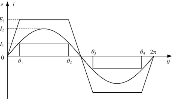
Basically, according to the shape of back electromotive force (EMF) waveforms, PMBL motors fall into the trapezoidal and sinusoidal back EMF types. In order to minimize the torque pulsation, the PMBL motor with trapezoidal back EMF is usually fed by a rectangular phase current, so-called the BLDC operation; whereas the PMBL motor with sinusoidal back EMF is usually fed by a sinusoidal phase current, so-called the BLAC operation.
Since the back EMF waveform of the flux-mnemonic
DSPM motor is alike a trapezoid rather than a sinusoid, the
motor usually performs BLDC operation. On the other hand, in
case the torque pulsation insignificant, it can also perform
BLAC operation. Fig. 2 shows the corresponding operation
waveforms, where E
1is the amplitude of the trapezoidal back
EMF, I
1and I
2are the amplitudes of the rectangular and
sinusoidal currents respectively, and θ
i(i=1, 2, 3, 4) stands for
the turn-on or turn-off electrical rotor position in the BLDC
operation with θ
2−θ
1=θ
4−θ
3=4π/5.
e i E
1I
1I
2θ
1θ
2θ
3θ
40 2π θ
Fig. 2. Operation waveforms under BLDC and BLAC operations.
By neglecting the reluctance torque component in the motor, the electromagnetic torque T
1during BLDC operation and T
2during BLAC operation are expressed respectively as:
ω
1 11
4 I E
T = (1)
ω 2 5
2 22
I
T = E (2)
where ω is the electrical angular velocity, E
2is the amplitude of the fundamental component of the back EMF. By applying Fourier analysis to the back EMF waveform to find out the relationship between E
1and E
2, and then setting (1) equal to (2) to maintain the same torque, the current amplitudes yield:
1 2
1 . 12 I
I = (3)
In an electric machine, the magnetic field plays a very important role in electromechanical energy conversion.
Namely, the same electromechanical property (such as the torque) can be maintained as long as the rotating magnetomotive force (MMF) keeps unchanged, which is produced by the variations of all five phase currents in both time and space.
Under open-circuit fault, although the spatial distribution of currents in healthy phases cannot be changed, the amplitudes and temporal distribution of currents are controllable. So, a remediation strategy, named field-reconfiguration, is proposed to handle this fault. By introducing torque-equivalent BLAC operation into the flux-mnemonic DSPM motor, the realization of field-reconfiguration becomes simpler since the corresponding MMF is always in terms of sinusoidal currents.
Under the normal BLAC operation, the phase currents are regulated to be 5-phase sinusoidal in time as given by:
( )
( )
( )
( )
⎪ ⎪
⎪
⎩
⎪⎪
⎪
⎨
⎧
+
=
+
=
−
=
−
=
=
5 π 2 cos
5 π 4 cos
5 π 4 cos
5 π 2 cos cos
2 e
2 d
2 c
2 b
2 a
θ θ θ θ θ
I i
I i
I i
I i
I i
(4)
So, the current phasors are plotted as shown in Fig. 3.
Fig. 3. Phasor diagram of 5-phase currents under normal BLAC operation.
The rotating MMF generated by these phase currents can be expressed as the sum of the MMFs of all five phases:
θ
NIe
jNi Ni Ni Ni Ni 2 5
e 4 d 3 c 2 b a
=
+ + + +
= a a a a
MMF
(5)
where N is the number of turns per phase, and a = 1∠ 72
Dstands for the spatial distribution of phase currents.
For one phase (such as phase A) open-circuit fault, the corresponding current is set to zero. Thus, the rotating MMF is the sum of MMFs of the remaining four phases:
e 4 d 3 c 2
b
N i N i N i
i
N ′ + ′ + ′ + ′
′ = a a a a
F
MM (6)
By equating (6) and (5), and then setting
d
b
i
i ′ = − ′ , i
c′ = − i
e′ (7)
the new phase current expressions can be obtained as:
( )
( )
( )
( )
⎪ ⎪
⎪
⎩
⎪⎪
⎪
⎨
⎧
+
=
′
+
′ =
−
′ =
−
′ =
′ =
5 π cos 382 . 1
5 π 4 cos 382 . 1
5 π 4 cos 382 . 1
5 π cos 382 . 1 0
2 e
2 d
2 c
2 b
a
θ θ θ θ
I i
I i
I i
I i
i
(8)
The corresponding current phasors are shown in Fig. 4.
i
ei
bi
ci
d36º ω
Fig. 4. Phasor diagram of remaining 4-phase currents under remedial one-
phase open-circuit operation.
For two phases (such as phase A and phase B) open-circuit fault, the rotating MMF is the sum of MMFs of the remaining three phases:
e 4 d 3 c
2
N i ′′ + N i ′′ + N i ′′
′′ = a a a
F
MM (9)
By equating (9) and (5), and then setting
e
0
d c
′′ + i ′′ + i ′′ =
i (10)
the new phase current expressions can be obtained as:
( )
( )
⎪ ⎪
⎪
⎩
⎪⎪
⎪
⎨
⎧
′′ =
+
′′ =
−
′′ =
′′ =
=
′′
θ θ θ
cos 236 . 2
5 π 4 cos 618 . 3
5 π 2 cos 236 . 2 0 0
2 e
2 d
2 c
b a
I i
I i
I i
i i
(11)
The corresponding current phasors are illustrated in Fig. 5.
Fig. 5 Phasor diagram of remaining 3-phase currents under remedial two- adjacent-phase open-circuit operation.
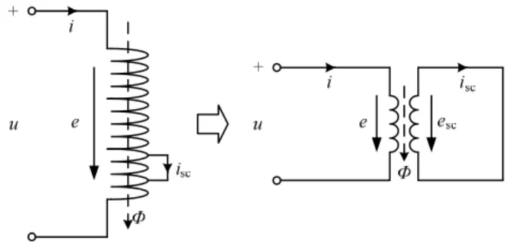
B. Short-circuit fault tolerance
The inter-turn short-circuit occurs in one phase winding can be analyzed by using a transformer equivalent circuit as shown in Fig. 6. The whole phase winding is the primary winding while the short-circuit winding is the secondary winding. By using the corresponding analysis method for transformer, the phase current i and short-circuit current i
sccan be obtained as:
⎪ ⎪
⎩
⎪⎪ ⎨
⎧
=
=
= −
R e R i e
R e i u
sc sc sc
(12)
where u is the terminal phase voltage, Φ is the flux per phase, e (e
sc) is the induced EMF in the phase winding (short-circuit winding), and R (R
sc) is the resistance of the phase winding (short-circuit winding).
Since the resistance of phase winding is usually very small and the turns of inter-turn short-circuit is also usually very few in most occasion, the influence on the phase current may actually be negligible. Nevertheless, the magnitude of short- circuit current is actually very large. Typically, the induced EMF e is usually 85%~95% of the terminal voltage u. So, after substituting e=0.9u into (12), it deduces:
i
i
sc= 9 (13)
which indicates that there is a large current circulating through the shorted turns. Consequently, it releases a large amount of heat energy which will worsen the inter-turn short-circuit.
Therefore, it is necessary to develop a remedial short-circuit operation.
Traditionally, the remediation of short-circuit fault is to disable the faulty phase. It is equivalent to transfer the short- circuit fault problem to the open-circuit fault problem, and then employ the open-circuit remediation. However, this traditional strategy suffers from two drawbacks: one is the lower efficiency due to the increase of currents flowing in the healthy phase windings; another is the larger torque ripple due to the presence of zero-torque zone. Thus, a new remediation strategy is proposed to enable the faulty phase continuing operation.
By using the analysis method for DSPM motor [30-32], e and T
eof the flux-mnemonic DSPM motor can be expressed as:
( )
dt Li d dt d dt N d
e = Φ = Ψ
PM+ (14)
m 2 m PM r
PM
e
2
1 θ
θ d
i dL d
i d T T
T = + = Ψ + (15)
where Ψ
PMis the PM flux linkage, L is the phase inductance, θ
mis the mechanical rotor position, T
PMis the PM torque component, and T
ris the reluctance torque component.
In order to reduce i
sc, it is required to decrease e as revealed in (12). So, from (14), if Ψ
PMcan be set to zero, e and hence i
scwill drop significantly. On the other hand, i will increase significantly as revealed in (12), hence compensating the reduction of T
edue to the vanishing of T
PMas indicated in (15).
According to the operation principle of the flux-mnemonic DSPM motor, the AlNiCo PMs can be easily demagnetized by applying a negative current pulse to the magnetizing winding.
So, the motor becomes operating at the demagnetizing mode.
Hence, the proposed remediation strategy for short-circuit fault can be named as mode-changing. It should be noted, the full- bridge inverter shown in Fig. 1(b) not only offers the bipolar armature current control for the magnetizing mode of operation, but also facilitates the unipolar armature current control for the demagnetizing mode of operation.
Fig. 6. Inter-turn short-circuit and its transformer equivalent circuit.
IV. S IMULATION R ESULTS
The time-stepping finite element method is a well-accepted numerical tool to analyze PM motor [33-35], which will be employed to simulate the proposed fault-tolerant operation of the flux-mnemonic DSPM motor. Firstly, the simulated output torque and five phase armature current waveforms under the normal BLDC and BLAC operations are shown in Fig. 7 and Fig. 8 respectively. It can be seen that the same output torque can be resulted from armature currents with different shapes and amplitudes, whereas the torque ripple at BLAC operation is slightly larger than that at BLDC operation [36]. Secondly, the output torque and five phase armature current waveforms under remedial one-phase and remedial two-phase open-circuit operations are simulated as illustrated in Fig. 9 and Fig. 10 respectively, where with amplitude augment and phase shift of the current in remaining healthy phases, the equivalent torques can be still offered even though associated with a larger ripple.
Thirdly, by purposely allowing the motor working in the demagnetizing mode, the same output torque can be maintained by increasing the armature currents. The simulated output torque and armature current waveforms under remedial short-circuit operation are shown in Fig. 11.
Fig. 7. Simulated output torque and armature current waveforms under normal BLDC operation.
Fig. 8. Simulated output torque and armature current waveforms under normal BLAC operation.
Torque (Nm)Five phase currents (A)