FPGA-Based Neural Fuzzy Controller Design for PMLSM Drive
Ying-Shieh Kung, Nguyen Khanh Quang and Le Thi Van Anh Department of Electrical Engineering
Southern Taiwan University Tainan, Taiwan, R. O. C. 710
Abstract—Based on the technology of field programmable gate array (FPGA), a realization of fuzzy control (FC) system with radial basis function neural network (RBF NN) tuning is presented to a permanent linear synchronous motor (PMLSM) drive in this paper. Firstly, a mathematic model of the PMLSM drive is defined; then to increase the performance of the PMLSM drive system, an FC constructed by a fuzzy basis function and its parameter adjustable mechanism using RBF NN is applied to the position control loop of the PMLSM drive system to cope with the effect of the system dynamic uncertainty and the external load. Secondly, FPGA by using finite state machine (FSM) method is presented to realize the aforementioned controllers, and VHSIC hardware description language (VHDL) is adopted to describe the circuit of the FSM. Finally, an experimental system is established to verify the effectiveness of the proposed FPGA-based neural fuzzy control system for PMLSM, and some experimental results are confirmed theoretically.
Keywords- FPGA; Neural fuzzy controller; PMLSM; Finite state machine ; VHDL;
I. INTRODUCTION
PMLSM has been increasingly used in many automation control fields as actuators [1-3], due to its advantages of superior power density, high-performance motion control with fast speed and better accuracy. However, the PMLSM does not use conventional gears or ball screws, so the payload upon the mover greatly affects the positioning performance [4]. To cope with this problem, many intelligent control techniques [5-6], such as FC, neural networks control (NNC), etc. have been developed and applied to the position control of the PMLSM drive to obtain high operating performance. Compared with other nonlinear approaches, FC has two main advantages, as follows: (1) FC has a special non-linear structure that is universal for various or uncertainty plants. (2) The formulation of FC rule can be easily achieved by control engineering knowledge, such as dynamic response characteristics, and it doesn’t require a mathematical model of controlled plant.
However, it is not an easy task to obtain an optimal set of fuzzy membership functions and rules in FC. In literatures, the genetic algorithm method [7] or gradient descent method are all possible methods to solve this problem. But, to obtain an optimal set of fuzzy membership functions and rules, the FC
will become further complication in overall computation;
therefore, limited fuzzy rules are used in their proposed method.
In this paper, a neural fuzzy controller (NFC) is proposed. For easy realization consideration, the membership functions in FC part are fixed and only defuzzifier parameters need to be tuned by using the gradient descent method. And a RBF NN is used to identify the plant dynamic and provide more accuracy plant information during parameters tuning of FC.
Although the execution of NNC or FC requires many computations, digital signal processor (DSP) and FPGA can provide a solution in this issue [8-9]. Especially, FPGA with programmable hard-wired feature, fast computation ability, shorter design cycle, embedding processor, low power consumption and higher density is better for the implementation of the digital system [10-12] than DSP.
Recently, Li, T.S. [13] utilized an FPGA to implement autonomous fuzzy behavior control on mobile robot. Lin, F.J.
[9] presented a fuzzy sliding-mode control for a linear induction motor drive based on FPGA. But, due to the fuzzy inference mechanism module adopts parallel processing circuits, it consumes much more FPGA resources; therefore limited fuzzy rules are used in their proposed method. To solve this problem, a FSM [14] joined by some multipliers, some adders, a look-up table (LUT), some comparators and registers are proposed to model the NFC algorithm of the PMLSM drive system. Due to the FSM belongs to the sequential processing method; the FPGA resources usage can be greatly reduced. In this paper, FPGA chip employed is an Altera Stratix II EP2S60F672C5 [15] which has 48,352 ALUTs, maximum 492 user I/O pins, 36 DSP blocks, 2,544,192 bits of RAM, and a Nios II processor, which can be embedded into FPGA. Finally, an experimental system including an FPGA experimental board, an inverter and a PMLSM, is set up to verify the correctness and effectiveness of the proposed NFC controller.
II. SYSTEM DESCRIPTION OF PMLSMDRIVE AND THE
CONTROLLER DESIGN
The internal architecture of the proposed FPGA-based NFC controller system for a PMLSM drive is shown in Fig. 1. A position command, a NFC in position loop, a P controller in speed loop and a current vector control scheme for PMLSM are all realized in one FPGA.
iww
i
Z 3-Phase inverter PWM1 PWM2 PWM3 PWM4 PWM5 PWM6
iuu
i
U
V W
Comparator circuit
Rectifier
AC source
A/D
AB
Z Z B
B A A
, ,
, ,
Z Z B
B A A
, ,
, , LPF
A/D LPF
Current control loop FPGA-based position control IC
PMLSM
Trajectory Computation Motion command
Linear encoder Nios II Processor
Encoder Interface
& transformation Current Vector Controller for PMLSM Drive Kv
*q
* i xp
xp
xm Reference
Model (RM)
+ _
1 z1
_
RBF Neural Network
+ _ Fuzzy Controller
xrbf
enn Adjusting Mechanism
u
u e
Jacobian
xp
e
Position control loop
Speed controller
+ 1 Z1
KI
uf
KP +
1
Z
2
Z
Fig.1 The architecture of an FPGA-based NFC for PMLSM drive system
A. Mathematical model of the PMLSM drive
The dynamic model of a typical PMLSM can be described in the synchronous rotating reference frame, as follows
d d q p d q d d s d
i L L x i L L R dt
di 1 v
(1)
q q p q
f q q s d p q
q d v
L x 1 i L
L i R L x L dt
di
(2)
where vd, vq are the d and q axis voltages; id, iq, are the d and q axis currents, Rs is the phase winding resistance; Ld, Lq are the d and q axis inductance; xp is the translator speed; is f the permanent magnet flux linkage; is the pole pitch. The developed electromagnetic thrust force is given by
q f d q d
e L L i i
F (( ) )
2
3
(3)
The current control of a PMLSM drive is based on a vector control approach. That is, if we control id to 0, the PMLSM will be decoupled, so that control a PMLSM will become easy as to control a DC linear motor. After simplification and considering the mechanical load, the model of a PMLSM can be written as the following equations,
q t q f
e i Ki
2
F 3
(4)
with
f
Kt
2
3 (5)
and the mechanical dynamic equation of PMLSM is dt
B dx dt
x M d F
Fe L m 2p m p
2 (6)
where Fe,Kt,Mm,Bm and FLrepresent the motor thrust force, the force constant, the total mass of the moving element, the viscous friction coefficient and the external force, respectively.
B. Neural fuzzy controller (NFC) in position control loop The dash rectangular area in Fig. 1 presents the architecture of an NFC for the PMLSM drive. It consists of a FC, a reference model and a RBF NN based parameter adjusting mechanism. Detailed description of these is as follows.
(1) Fuzzy controller (FC):
In Fig.1, the tracking error and the change of the error, e, de are defined as
) ( ) ( )
(k x k x k
e m p (7)
) 1 ( ) ( )
(k ek e k
de (8)
and e, de and uf are input and output variables of FC, respectively. The design procedure of the FC is as follows:
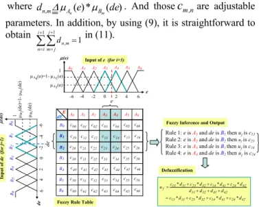
(a) Take the e and de as the input variables of the FC, and define their linguist variables as E and dE. The linguist value of E and dE are {A0, A1, A2, A3, A4, A5, A6} and {B0, B1, B2, B3, B4, B5, B6}, respectively. Each linguist value of E and dE is based on the symmetrical triangular membership function which is shown in Fig.2.
(b) Compute the membership degree of e and de. Figure 2 shows that the only two linguistic values are excited (resulting in a non-zero membership) in any input value, and the membership degree A(e)
i can be derived by
2
e e ei 1
Ai( )
and (e) 1 (e)
i 1
i A
A
(9)
where ei162*(i1). Similar results can be obtained in computing the membership degree B (de)
j .
(c) Select the initial fuzzy control rules by referring to the dynamic response characteristics, such as,
i j, f j
i and eisB THEN u is c A
is e
IF (10)
where i and j = 0~6, Ai and Bj are fuzzy number, and cj,i is real number. The graph of fuzzification and fuzzy rule table is shown in Fig. 2.
(d) Construct the fuzzy system uf(e,de) by using the singleton fuzzifier, product-inference rule, and central average defuzzifier method. Although there are total 49 fuzzy rules in Fig. 3 will be inferred, actually only 4 fuzzy rules can be effectively excited to generate a non-zero output. Therefore, the (11) can be replaced by the following expression:
m n i
i n
j j m
n i m
i n
j j m
B A i
i n
j j m
B A n m
f c d
de e
de e c de
e u
m n
m n
,
1 1
1 1 ,
1 1
,
* )
(
* ) (
)]
(
* ) ( [ )
,
(
(11)
where dn,mAn(e)*Bm(de). And those
c
m,nare adjustable parameters. In addition, by using (9), it is straightforward to obtain 1 1 1,
i
i n
j j m
m
dn in (11).
c00 dE
1 A0 A1 A2 A3 A4 A5 A6
0 6
-6 e
e E
de
de
(e)
(de) 1
A3(e)
A4(e)=1-A3(e)
B1(de)
B2(de)=1-B1(de)
Rule 1: e is A3and de is B1then ufis c13
Rule 2: e is A3and de is B2then ufis c23
Rule 3: e is A4and de is B1then ufis c14
Rule 4: e is A4and de is B2then ufis c24 Defuzzification
42 24 41 14 32 23 31 13
42 41 32 31
42 24 41 14 32 23 31 f 13
d c d c d c d c
d d d d
d c d c d c d u c
*
*
*
*
*
*
*
*
06-6
Fuzzy Rule Table Input of e (for i=3)
Input of de (for j=1)
Fuzzy Inference and Output A0 A1 A2 A3 A4 A5 A6
c01 c02 c03 c04 c05 c06 c10 c11 c12 c13 c14 c15 c16 c20 c21 c22 c23 c24 c25 c26 c30 c31 c32 c33 c34 c35 c36 c40 c41 c42 c43 c44 c45 c46 c50 c51 c52 c53 c54 c55 c56 c60 c61 c62 c63 c64 c65 c66 B0
B1 B2 B3 B4 B5 B6 B0B1B2B3B4B5B6
4 2 -4 -2
42-4-2
Fig. 2. The symmetrical triangular membership function of e and de, fuzzy rule table, fuzzy inference and fuzzification
(2) Radial basis function neural network (RBF NN)
The RBF NN adopted here is a three-layer architecture which is shown in Fig. 3 and comprised of one input layer, one hidden layer and one output layer.
The RBF NN has three inputs byu(k), xp(k1) and )
2 (k
xp , and its vector form is represented by
T p
p k x k
x k u
X [ ( ), ( 1), ( 2)] (12)
. Furthermore, the multivariate Gaussian function is used as the activated function in hidden layer of RBF NN, and its formulation is shown as follows.
q c r
h X
r r
r ), 1,2,3,4,....
exp( 2 2
2
(13)
where cr [cr1,cr2,cr3]Tand rdenote the node center and node variance of rth neuron, and Xcr is the norm value which is measured by the inputs and the node center at each neuron. And the network output in Fig. 3 can be written as
q
r r r
rbf w h
x
1
(14) where xrbf is the output value; w and r h are the weight and r output of rth neuron, respectively.
The instantaneous cost function is defined as
2 2
2 ) 1 2(
1
nn p
rbf x e
x
J (15)
then according to the gradient descent method, the learning algorithm of weights, node center and variance are as follows:
) ( ) ( ) ( ) 1
(k w k e k h k
wr r nn r (16)
) (
) ( ) ) ( ( ) ( ) ( ) ( ) 1
( 2
k k c k k X h k w k e k c k c
r rs s r r nn rs
rs (17)
) (
) ( ) ) ( ( ) ( ) ( ) ( ) 1
( 3
2
k k c k k X h k w k e k k
r r r
r nn r
r
(18)
where r=1,2,..q, s=1,2,3 and is a learning rate. Further, the u
xp
is Jacobian transformation and can be derived from Fig.3
q
r r
r r r rbf
p c u k
h u w
x u x
1 2
1 ( )
(19)
(3) Adjusting mechanism of fuzzy controller
The gradient descent method is used to derive the FC control law in Fig. 1. The adjusting of FC parameters is to minimize the square error between the mover position and the output of the reference model. The instantaneous cost function is defined by
2
2 ( )
2 1 2 1
p m
e e x x
J (20)
and the parameters of cm,n are adjusted according to
n m
e n
m e n
m c
J c
c J
, ,
,
(21)
with m = j, j+1, n = i,i+1 and where represents learning rate.
The chain rule is used and the partial differential equation for Je in (20) can be written as
n m
f f p n
m e
c u u e x c
J
,
,
(22)
From (11), we can get
m n n
m
f d
k c
k u
,
, ( )
)
(
(23)
And using Jocobian formulation from (19)
2 1 1
) ) (
( )
(
r r q r
r r i P rbf i P f
p K K wh c u k
u K x u K
x
(24) Therefore, (23) and (24) are substituted into (22), and then the parameters cm,nof fuzzy controller described by (11) can be adjusted using the following expression.
2 1 1
, ,
) ) (
)(
( ) (
r r q
r r r m n i p n
m
k u h c w d K K k e k
c
(25) with m = j, j+1 and n = i,i+1.
) (k u
) 1 (k x
) 2 (k x
x
rbfw1
w2
h1
wq
h2
hq
Input layer Hidden layer Output layer
) (k xp
enn + -
Fig.3 RBF neural network
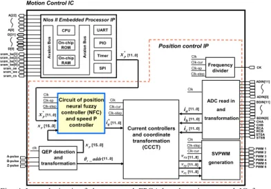
III. DESIGN OF A FPGA-BASED NFC FOR PMLSMDRIVE
The internal architecture of the proposed FPGA-based motion control IC for PMLSM drive is shown in Fig. 4. The FPGA uses Altera Stratix II EP2S60 which has 48,352 ALUTs, maximum 718 user I/O pins, total 2,544,192 RAM bits, and a Nios II embedded processor is downloaded into FPGA to construct an SoPC environment. The motion control IC which comprises a Nios II embedded processor IP and a position control IP, is designed under the SoPC environment. The position control IP implemented by hardware is adopted to realize the function of a position NFC and speed P controller, a current controller and coordinate transformation (CCCT), SVPWM generation, QEP detection and transformation, ADC interface, etc. The sampling frequency of current control is designed with 16 kHz. The operating clock rate of the designed FPGA controller is 50MHz and the frequency divider generates 50 Mhz (Clk), 25 MHz (Clk-step), 12 kHz (Clk-cur) and 2 kHz (Clk-sp) clock to supply all module circuits of the position control IP.
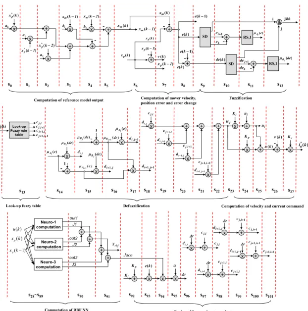
An FSM is employed to model the NFC in position loop and P controller in speed loop which is shown in Fig. 5, which uses adders, multipliers and registers, etc. and manipulates 102 steps machine to carry out the overall computation. With exception of the data type in reference model are 24-bits, others data type are designed with 12-bits length, 2’s complement and Q11 format. Although the algorithm of the NFC is highly complexity, the FSM can give a very adequate modeling and easily be described by VHDL. Furthermore, steps s0~s5 execute the computation of reference model output;
steps s6~s8 are for the computation of velocity, position error and error change; steps s9~s13 execute the fuzzification and look-up fuzzy table; s14~s22 are for the defuzzification; s23~s27
are the computation of velocity and current command; s28~s91
describe the computation of RBF NN and Jacobian transformation; finally s92~s101 execute the tuning of fuzzy rule parameters. The operation of each step in Fig.5 can be completed within 40ns (25 MHz clock) in FPGA; therefore total 102 steps need a 4.08s operation time.
Clk Clk-cur
[11..0]
[11..0]
A-pulse
STSB RCBRCA STSA CHB CHA
SVPWM generation ADC read in
and transformation
Frequency divider
QEP detection and transformation
[11..0]
[11..0]
[11..0]
CK
B-pulse Z-pulse
PWM 1 PWM 2 PWM 3 PWM 4 PWM 5 PWM 6 ADIN[11]
ADIN[0]
BDIN[11]
BDIN[0]
Clk-sp
clk CPU
On-chip ROM On-chip
RAM
UART PIO Timer
SPI
Avalon Bus
Avalon Bus
Nios II Embedded Processor IP Motion Control IC
Position control IP
sram_cs sram_wesram_oe sram_be[3]
sram_be[2]
sram_be[1]
sram_be[0]
D[31]
D[0]
A[22]
A[0]
Current controllers and coordinate transformation
(CCCT)
e_addr
[11..0]
*q i
[11..0] vrx
vry vrz
ia ib
[11..0]
ic [15..0]
xp Clk
Clk Clk-step Clk
Clk-cur Circuit of position
neural fuzzy controller (NFC)
and speed P controller [15..0]
xp Clk Clk-sp
[11..0]
*
xp[11..0]
Clk-step
Clk-step Clk-cur
*
xp
Clk-step
Fig. 4 Internal circuit of the proposed FPGA-based motion control IC for PMLSM drive
The Nios II embedded processor IP is depicted to perform the function of the position command in software, which includes main program and the interrupt service routine (ISR) by 2ms sampling interval. All programs are coded in the C programming language. Then, through the complier and linker operation in the Nios II IDE (Integrated Development Environment), the execution code is produced and can be downloaded to the external Flash or SDRAM via JTAG interface. Finally, the FPGA utility of the motion control IC is evaluated. The circuit of a NFC uses 19,225 ALUTs resource and the overall circuits included a Nios II embedded processor IP (4,744 ALUTs and 45,824 RAM bits) as well as a position control IP (22,954 ALUTs and 301,056 RAM bits) in Fig.4, use 57.3% ALUTs resource and 13.6% RAM resource of Stratix II EP2S60.
IV.
E
XPERIMENTS ANDR
ESULTSThe overall experimental system depicted in Fig.1 includes an FPGA (Stratix II EP2S60F672C5), a voltage source IGBT inverter and a PMLSM. The PMLSM was manufactured by the BALDOR electric company; and it is a single-axis stage with a cog-free linear motor and a stroke length with 600mm. The parameters of the motor are: Rs = 27, Ld = Lq = 23.3 mH, Kt = 79.9N/A. The input voltage, continuous current, peak current (10% duty) and continuous power of the PMLSM are 220V, 1.6A, 4.8A and 54W, respectively. The maximum speed and acceleration are 4m/s and 4 g but depend on external load. The moving mass is 2.5Kg, the maximum payload is 22.5Kg and the maximum thrust force is 73N under continuous operating conditions. A linear encoder with a resolution of 5m is mounted on the PMLSM as the position sensor, and the pole pitch is 30.5mm (about 6100 pulses). The inverter has three sets of IGBT power transistors. The collector-emitter voltage of the IGBT is rated 600V; the gate-emitter voltage is rated 20V, and the DC collector current is rated 25A and in short time (1ms) is 50A. The photo-IC, Toshiba TLP250, is used in the gate driving circuit of IGBT. Input signals of the inverter are PWM signals from the FPGA device.
The dynamic performance of PMLSM drive is evaluated while the NFC is applied in the position control loop of Fig. 1.
The control sampling frequency of the current, speed and position loops are designed as 16kHz, 2kHz and 2kHz, respectively. In the proposed motion control IC, the current controller, the speed controller and the NFC are all realized by hardware in FPGA. The speed controller adopts a P controller with gain Kv=1.1. The NFC is used in the position loop, the membership function and the initial fuzzy rule table are designed, and the PI gains are chosen by Kp=0.3, Ki=0.003.
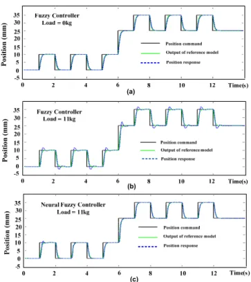
The transfer function of the reference model is a second order system with the natural frequency of 20 rad/s and damping ratio of 1. Figure 6 shows the position step responses of the mover using the FC and NFC when the position command is a 0.5Hz square wave with amplitude varied at 0~10mm and 25~35mm. The parameters ci,j of the fuzzy rule table are adequately selected at the 0kg external load condition, and
-+ x
x +
x + x
s0 s1 s2 s3 s4 s5
x
+ -
-+
s6
-+
+ -
s7 s8 )
*(k xp
) (k 1 xp
) (k 1 xp )
(k 1 xm
) (k 1 xm
) (k v
) (k e
) 1 (k e
) 1 (k e a0
a1
a2
b1 b2
s9
Computation of reference model output Computation of mover velocity, position error and error change
s14 x
+ -1 )
i(e
A )
j(de
B j
di,
-+
x
x
x
s15 s16 s17
)
j(de
B
) e
i ( A1
1
) de
j ( B1
j , di1
1 j , di
1 1
j, di )
j(de
B
)
i(e
A
s18
x
x +
x
x
+ + x +
ui
x +
s20 s21 s23 s24
s19 s22 s25
i cj,
i, cj1
1 i, cj
1 1
i, cj j
di,
j
di1,
1 , 1
j
di 1
,j
di
Ki
Kp
uf
)
*(k iq ui
Defuzzification Computation of velocity and current command
-+
-+
&
i j
j&i
s10 s11 s12
s13
) (k de
)
i(e
A
)
j(de
B
i cj,
1 i, cj
i, cj1
1 1
i, cj
1 ei
1 dej
Look-up Fuzzy rule
table
RS,1
RS,1
Fuzzification SD
ek
SD dek )
(k e
)
*(k 1 xp
)
*(k 2 xp
) (k 2 xm
) (k xm
) (k xm
) (k xp
) (k xp
+ ) (k v
x
Kv
-
s26 s27 ) (k u
Look-up fuzzy table
s92 s93 s96
x +
i cj,
i, cj1
1 i, cj
1 1 j i, c
i, cj1
1 i, cj
j
di,
j , di1
1 1
j, di
+ x x
α Ki
Kp e(k)
i cj,
x +
1 ,j
di
x +
x +
s97 s98 s99 s100 s101
r
r
r
r
r
1 1
i, cj
Tuning of fuzzy rule parameters x
s94 s95
s28~s89 s90
) (k u
) (k xp
) 1 (k xp
Neuro-1 computation
Neuro-2 computation
Neuro-3 computation
+ out1
out2
out3 J1
J2
J3 +
+ rbf x
+ Jaco
s91 j&i
Computation of RBF NN
Fig. 5 State diagram of an FSM for describing the neural fuzzy controller in position loop and P controller in speed loop
the step response shows a good dynamic response with a rising time of 0.2s, no overshoot and a near-zero steady state in Fig.
6(a). However, when 11 kg external load is added upon the mover and the same fuzzy control rule table and controller parameters are used, the position dynamic response worsens and exhibits a 19.5% overshoot in Fig. 6(b). It reveals that the dynamic performance of the PMLSM is affected by the external load on the mover. Accordingly, a NFC is adopted in Fig.1 to solve this problem. When the proposed NFC is used with learning rate being 0.05, the tracking results are highly improved and presented in Fig. 6(c). Initially, the mover of the PMLSM tracks the output of the reference model with overshoot. After one or two square wave commands, the ci,j
parameters are tuned to adequate values, and the mover can closely follow the output of the reference model. Further, a frequency response is considered to evaluate the performance of the proposed controller. A tested input signal of a sinusoid wave with 10mm amplitude and the frequency variation from initial 1 Hz to final 3 Hz is provided. In this design, the frequency tracking response and the tracking error of the
PMLSM without and with adaptation under 11kg external load are shown in Fig. 7 and Fig. 8. Figure 8 reveals that the position tracking error by using the NFC is only about 0.35 times of that obtained by using the FC in Fig.7. However, Fig.
7 reveals that the phase lag phenomenon using the FC is more serious than using the NFC in Fig.8. Therefore, the experimental results in Figs. 6 to 8 demonstrate that the proposed FPGA-based NFC for the PMLSM drive is effective and robust.
V. CONCLUSIONS
This study successfully presents a NFC for PMLSM drive based on FPGA technology. The work herein is summarized as follows. (1) The functionalities required to build a fully digital motion controller of PMLSM drive have been integrated in one FPGA chip. (2) The behavior of a NFC has been successfully described by VHDL. Finally, some experimental results are verified the effectiveness of the proposed controller system.
Position (mm)
(a)
(b)
(c)
Position (mm)
Fig. 6 Step response at 0~10mm to 25~35mm square save command under case of (a) FC without external load (b) FC with 11 Kg external load (c) NFC with 11Kg external load
1 Hz
3 Hz
2.1 mm -2.0 mm
2.4 mm
-2.2 mm (a)
(b)
Fig. 7 (a) Position frequency and (b) error response for a 1Hz-3Hz sinusoid input signal using FC under external load 11Kg
1 Hz
3 Hz
0.8 mm -0.7 mm
0.8 mm
-0.7 mm
(a)
(b)
Fig. 8 (a) Position frequency and (b) error response for a 1Hz-3Hz sinusoid input signal using NFC under external load 11Kg
ACKNOWLEDGMENT
This work was supported by National Science Council of the R.O.C. under grant no. NSC 98-2221-E-218-050-MY2.
REFERENCES
[1] F. Gieras and Z.J. Piech, Linear synchronous motors – transportation and automation systems, CRC Press, 2000.
[2] P.K. Budig, “The application of linear motors,” Proceedings, PIEMC 2000. The 3rd international, 2000, vol. 3, pp.1336-1340.
[3] G.W. McLean, “Review of recent progress in linear motors,” IEE Proc., Part B, vol. 135, no. 6, pp. 380-416, November 1988.
[4] T.H. Liu, Y.C. Lee and Y.H. Chang, “Adaptive controller design for a linear motor control system,” IEEE Trans. on Aerospace and Electronics System, vol. 40, no.2, pp. 601-613, April 2004.
[5] G. Qingding, H. Qingtao and Q. Yanli, “Neural network real-time IP position controller on-line design for permanent magnetic linear synchronous motor,” The 7th International on Advanced motion control, 2002, pp. 386-389.
[6] Y.S. Kung, R.F. Fung and T.Y. Tai, “Realization of a motion control IC for X-Y Table based on novel FPGA technology”, IEEE Trans. Ind.
Electron., vol. 56, no. 1, pp. 43-53, Jan. 2009.
[7] K.F. Man, K.S. Tang, Z.F. Liu and S. Kwong, "Minimal fuzzy memberships and rules using hierarchical genetic algorithms", IEEE Trans. on Ind. Electron., vol. 45, no.1., pp. 162-169, Feb., 1998.
[8] Y.S. Kung, “Design and implementation of a high-performance PMLSM drives using DSP chip,” IEEE Trans. on Ind. Electron., vol. 55, no. 3, pp. 1341-1351, March 2008.
[9] F.J. Lin, D.H. Wang and P.K. Huang, “FPGA-based fuzzy sliding mode control for a linear induction motor drive,” IEE Proc.- Electr. Power Application, vol. 152, no.5, pp. 1137-1148, 2005.
[10] E. Monmasson and M. N. Cirstea, “FPGA design methodology for industrial control systems – a review” IEEE Trans. Ind. Electron., vol.
54, no.4, pp.1824-1842, Aug. 2007.
[11] Y.S. Kung and M.H. Tsai, “FPGA-based speed control IC for PMSM drive with adaptive fuzzy control,” IEEE Trans. on Power Electronics, vol. 22, no. 6, pp. 2476-2486, Nov. 2007.
[12] H.C. Huang and C.C. Tsai, “FPGA Implementation of an embedded robust adaptive controller for autonomous omnidirectional mobile Platform,” IEEE Trans. Ind. Electron., vol. 56, no. 5, pp. 1604-1616, May 2009.
[13] T.S. Li, S.J. Chang and Y.X. Chen, “Implementation of human-like driving skills by autonomous fuzzy behavior control on an FPGA-based car-like mobile robot,” IEEE Trans. Ind. Electron., vol. 50, no. 5, pp.
867-880, 2003.
[14] Y.C. Hsu, K.F. Tsai, J.T. Liu and E.S. Lin, VHDL modeling for digital design synthesis, KLUWER ACADEMIC PUBLISHERS, TOPPAN COMPANY (S) PTE LTD, 1996.
[15] Website: http://www.altera.com